EP0986246A2 - Bildverarbeitungssytem - Google Patents
Bildverarbeitungssytem Download PDFInfo
- Publication number
- EP0986246A2 EP0986246A2 EP99117584A EP99117584A EP0986246A2 EP 0986246 A2 EP0986246 A2 EP 0986246A2 EP 99117584 A EP99117584 A EP 99117584A EP 99117584 A EP99117584 A EP 99117584A EP 0986246 A2 EP0986246 A2 EP 0986246A2
- Authority
- EP
- European Patent Office
- Prior art keywords
- reference value
- density
- white reference
- calculating
- black
- Prior art date
- Legal status (The legal status is an assumption and is not a legal conclusion. Google has not performed a legal analysis and makes no representation as to the accuracy of the status listed.)
- Granted
Links
Images


Classifications
-
- H—ELECTRICITY
- H04—ELECTRIC COMMUNICATION TECHNIQUE
- H04N—PICTORIAL COMMUNICATION, e.g. TELEVISION
- H04N1/00—Scanning, transmission or reproduction of documents or the like, e.g. facsimile transmission; Details thereof
- H04N1/40—Picture signal circuits
- H04N1/407—Control or modification of tonal gradation or of extreme levels, e.g. background level
- H04N1/4072—Control or modification of tonal gradation or of extreme levels, e.g. background level dependent on the contents of the original
- H04N1/4074—Control or modification of tonal gradation or of extreme levels, e.g. background level dependent on the contents of the original using histograms
Definitions
- the present invention relates to an image processing system applied to an image processing apparatus, for example, a digital copying machine to which an image of an original read by means of a scanner is input, and which subjects the input image to predetermined image processes, such as a density adjusting process, and outputs the processed image onto a paper sheet by means of an electrophotography laser printer.
- an image processing apparatus for example, a digital copying machine to which an image of an original read by means of a scanner is input, and which subjects the input image to predetermined image processes, such as a density adjusting process, and outputs the processed image onto a paper sheet by means of an electrophotography laser printer.
- image data is read from an original by image reading means, e.g., a scanner, and digitized.
- the digital image data is processed in accordance with the purpose, multileveled, and output through image output means, e.g., a laser printer.
- image output means e.g., a laser printer.
- a method in which a density histogram is made on the basis of the input image data, the kind of the input original (whether the background is light or dark) is determined on the basis of the characteristic value of the density histogram, a reference value is obtained from the result of the determination, and the density of the input image data is adjusted in accordance with the reference value.
- a reference value means a value used for automatically adjusting the density of an image by means of the characteristic value of an original.
- a white reference value is obtained for adjusting the density of a background and a black reference value is obtained for adjusting the density of a letter.
- An image density is adjusted by means of the two reference values. However, if the two reference values are very close, the density of lightly printed letters may be uneven, or a dark background cannot be removed and may remain like noise in places. In this case, the image quality may often be deteriorated.
- the range for determining a white reference value cannot overlap the range for determining a black reference value, the dark background cannot be completely removed or a light-colored letter cannot be darkened.
- an object of the present invention is to provide an image processing method, by which automatic adjustment for removing a background or darkening a light letter can be performed suitably without failure.
- an image processing method comprising the steps of:
- the calculating step includes: calculating a second white reference value by giving a first offset to the first white reference value; and calculating a second black reference value by giving a second offset to the first black reference value, and
- the calculating step includes: calculating as the first white reference value a density having a maximum frequency in a first predetermined density range for determining a white reference value; and calculating as the first black reference value a density having a maximum frequency in a second predetermined density range for determining a black reference value, wherein the first and the second predetermined density ranges partially overlap.
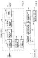
- FIG. 1 is a block diagram showing the structure of a digital copying machine to which an image processing method of the present invention is applied.
- the control system of the present invention is constituted by three CPUs (central processing units): a main CPU 91 in a main control unit 90, a scanner CPU 100 in a scanner unit 4 and a printer CPU 110 in a printer unit 6.
- the main CPU 91 and the printer CPU 110 perform bidirectional communications via a common RAM 95.
- the main CPU 91 transmits operation instructions to the printer CPU 110, and the printer CPU 110 transmits a status signal in return.
- the printer CPU 110 and the scanner CPU 100 perform serial communications, in which the printer CPU 110 transmits operation instructions to the scanner CPU 100 and the scanner CPU 100 transmits a status signal in return.
- the main control unit 90 comprises the main CPU 91, a ROM 92, a RAM 93, a NVRAM (nonvolatile RAM) 94, the common RAM 95, an image processor 96, a page memory controller 97, a page memory 98, a printer controller 99, and a printer font ROM 121.
- the main CPU 91 controls the overall operations.
- the ROM 92 stores control programs and the like.
- the RAM 93 temporarily stores data.
- the common RAM 95 is used to perform bidirectional communications between the main CPU 91 and the printer CPU 110.
- the printer font ROM 121 stores font data corresponding to print data.
- the printer controller 99 develops print data supplied from an external device 122, such as a personal computer, to image data by means of the font data stored in the printer font ROM 121 with a resolution corresponding to the data representing the resolution appended to the print data.
- the scanner unit 4 image reading means for reading an image from the original, comprises: the scanner CPU 100 for controlling the scanner unit; a ROM 101 storing control programs and the like; a RAM 102 for storing data; a CCD driver 103 for driving a line sensor for photo-electrically converting light reflected from the original to an electric signal; a scanning motor driver 104 for controlling rotation of a scanning motor for moving an exposure lamp for radiating light to the original and moving a mirror for guiding the light reflected from the original to the line sensor; and an image corrector 105.
- the image processor 96, the page memory 98, the printer controller 99, the image corrector 105 and the laser driver 113 are connected to one another through a image data bus 120.
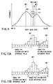
- FIG. 5 shows an example of the density histogram.
- the accuracy of the abscissa must be selected in accordance with the purpose. In the following description, the accuracy is assumed to be 4 bits (16 levels).
- the 8-bit density data supplied from the scanner unit 4 is converted to 4-bit density data to prepare a density histogram.
- the density level "1" represents density data of 00h (hex) to 0Fh. Therefore, the frequency (the height along the vertical axis) of the level "1" represents the sum of the numbers of pixels having the densities 00h to 0Fh.
- a white reference value is determined to fall under the range between a level 1 and, for example, a level 9, a comparatively high level as a background density.
- a white reference value is determined to fall under the range between the level 1 and, for example, a level 6, a comparatively low level.
- a black reference value to darkly print a comparatively light letter written by, for example, a pencil, a black reference value is determined to fall under the range between a level 9, a comparatively low level as a letter density, and a level 16.
- a black reference value is determined to fall under the range between a level 11, a comparatively high level, and the level 16.
- the ranges for determining white and black reference values are set so as not overlap.
- the ranges can overlap, as will be described later with reference to FIGS. 10B and 11B.
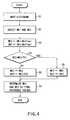
- the reference value calculating and correcting portion 202 calculates a white reference value WK1 and a black reference value BK1 (Step S2 in FIG. 4) as provisional reference values based on the peak positions WP and BP, from the following formulas (1).
- the formulas (1) represent reference values in the case of FIG. 5.
- WK1 (WP-1) ⁇ 256 16 + 16 2 + H(WP + 1) - H(WP - 1) H(WP) ⁇ 16 2
- BK1 (BP-1) ⁇ 256 16 + 16 2 + H(BP + 1) - H(BP - 1) H(BP) ⁇ 16 2
- the reference value calculating and correcting portion 202 corrects the provisional reference values WK1 and BK1 with offset values W offset and B offset based on the following formulas (2), and outputs the corrected reference values WK2 and BK2.
- WK2 WK1+W offset
- BK2 BK1+B offset
- the intermediate density data between the two values WK2 and BK2 may be extended widely.
- the intermediate density data may be distributed in a wide range of density. In this case, a region of the print where the density is darker than that of the corresponding region of the original looks like a noise, resulting in deterioration in the quality of the image.
- the white reference value when offsets are given, it is necessary that the white reference value be always smaller than the black reference value, in view of the sense of the white reference value and the black reference value. For this reason, according to the conventional art, the range for determining a white reference value and the range for determining a black reference could not overlap, on the assumption of various histograms of originals. If they are allowed to overlap, as shown in FIG. 8, a white reference value may be greater than a black reference value, depending on conditions of offsets. In this case, the automatic density adjustment cannot function normally.
- the reference value determining portion 203 further corrects the reference values WK2 and BK2 calculated by the reference value calculating and correcting portion 202 based on the following formulas (3), and determines and outputs final reference values WK3 and BK3 (Steps S6 and S7 in FIG. 4).
- White Reference Value: WK3 WK2
- the black reference value BK3 is at least a predetermined value greater than a white reference value WK3.
- the range for determining the white reference value may overlap the range for determining the black reference value shown in FIG. 5.
- the range for determining the white reference value can be extended as shown in FIGS. 10B and 11B, so that a dark background portion can be surely detected. Therefore, the background can be removed easily.
- the range for determining the black reference value can be extended, so that a light letter can be surely detected. Therefore, the light letter can be darkly printed.
- FIGS. 10A and 10B show a case where the original has a dark background.
- FIGS. 11A and 11B show a case where the original has light letters.
- FIGS. 10A and 11A show ranges for determining a white reference value and a black reference value according to the conventional art.
- FIGS. 10B and 11B show ranges for determining a white reference value and a black reference value according to the present invention.
- the reference value determining portion 203 determines and outputs the white reference value WK3 and the black reference value BK3, which are finally used for the process.
- the automatic density adjusting portion 204 carries out an operation of the following formula (4), so that the image data supplied from the scanner 4 can be subjected to a density adjusting process using the white reference value WK3 and the black reference value BK3 determined by the reference value determining portion 203.
- D' D-WK3 BK3-WK3
- the image data output from the scanner unit 4 is converted as shown in FIG. 12.
- an abscissa represents an image density before the automatic density adjustment
- an ordinate represents an image density after automatic density adjustment.
- the density of every pixel having a density of WK3 or lower is converted to "00h”
- the density of every pixel having a density of BK3 or higher is converted to "FFh”.
- the density of a pixel having a density between WK3 and BK3 is converted to a density between "00h" and "FFh”.
- the present invention can provide an image processing method, by which automatic adjustment for removing a background or darkening a light letter can be performed suitably without failure, so that a clear image can be provided.
Landscapes
- Engineering & Computer Science (AREA)
- Multimedia (AREA)
- Signal Processing (AREA)
- Facsimile Image Signal Circuits (AREA)
- Control Or Security For Electrophotography (AREA)
- Image Processing (AREA)
- Image Input (AREA)
Applications Claiming Priority (2)
| Application Number | Priority Date | Filing Date | Title |
|---|---|---|---|
| JP25267798 | 1998-09-07 | ||
| JP25267798A JP4097800B2 (ja) | 1998-09-07 | 1998-09-07 | 画像処理方法および画像処理装置 |
Publications (3)
| Publication Number | Publication Date |
|---|---|
| EP0986246A2 true EP0986246A2 (de) | 2000-03-15 |
| EP0986246A3 EP0986246A3 (de) | 2001-03-14 |
| EP0986246B1 EP0986246B1 (de) | 2003-03-12 |
Family
ID=17240711
Family Applications (1)
| Application Number | Title | Priority Date | Filing Date |
|---|---|---|---|
| EP99117584A Expired - Lifetime EP0986246B1 (de) | 1998-09-07 | 1999-09-07 | Bildverarbeitungsverfahren und -gerät |
Country Status (4)
| Country | Link |
|---|---|
| US (1) | US6631209B1 (de) |
| EP (1) | EP0986246B1 (de) |
| JP (1) | JP4097800B2 (de) |
| DE (1) | DE69905827T2 (de) |
Cited By (1)
| Publication number | Priority date | Publication date | Assignee | Title |
|---|---|---|---|---|
| EP1221810A3 (de) * | 2000-12-28 | 2004-10-20 | Xerox Corporation | Adaptive Beleuchtungskorrektur abgetasteter Bilder |
Families Citing this family (17)
| Publication number | Priority date | Publication date | Assignee | Title |
|---|---|---|---|---|
| US6920245B1 (en) | 2000-11-22 | 2005-07-19 | Kabushiki Kaisha Toshiba | Image processing apparatus and image forming apparatus |
| US7057768B2 (en) * | 2001-07-02 | 2006-06-06 | Corel Corporation | Automatic color balance |
| JP3918479B2 (ja) * | 2001-09-11 | 2007-05-23 | セイコーエプソン株式会社 | シェーディング補正の基準データ設定方法及び画像読み取り装置 |
| JP2003248008A (ja) * | 2001-12-18 | 2003-09-05 | Inst Of Physical & Chemical Res | 反応液の攪拌方法 |
| JP4254204B2 (ja) * | 2001-12-19 | 2009-04-15 | 富士ゼロックス株式会社 | 画像照合装置、画像形成装置及び画像照合プログラム |
| US20030231194A1 (en) * | 2002-06-13 | 2003-12-18 | Texas Instruments Inc. | Histogram method for image-adaptive bit-sequence selection for modulated displays |
| US7466445B2 (en) * | 2003-07-14 | 2008-12-16 | Toshiba Corporation | Color and density calibration of color printers |
| KR100612494B1 (ko) * | 2004-06-07 | 2006-08-14 | 삼성전자주식회사 | 칼러 영상의 채도 조절 장치 및 방법 |
| JP4366318B2 (ja) * | 2005-01-11 | 2009-11-18 | キヤノン株式会社 | 画像処理装置及びその方法、プログラム |
| US20060203267A1 (en) * | 2005-03-10 | 2006-09-14 | Kabushiki Kaisha Toshiba | Image forming apparatus and image forming method |
| US20060274376A1 (en) * | 2005-06-06 | 2006-12-07 | Lexmark International, Inc. | Method for image background detection and removal |
| JP4282081B2 (ja) * | 2005-10-31 | 2009-06-17 | キヤノン株式会社 | 画像処理装置およびその方法 |
| JP4232804B2 (ja) * | 2006-08-25 | 2009-03-04 | 日本電気株式会社 | 画像濃度変換方法、画像強調処理装置、およびそのプログラム |
| KR101090059B1 (ko) * | 2007-06-12 | 2011-12-07 | 삼성전자주식회사 | 화상처리장치 및 그 쉐이딩 방법 |
| US8401290B2 (en) * | 2008-07-24 | 2013-03-19 | Libredigital, Inc. | Method and system for processing to enhance digital images |
| JP5327469B2 (ja) * | 2009-08-10 | 2013-10-30 | 富士ゼロックス株式会社 | 画像処理装置、画像処理プログラム |
| KR102615070B1 (ko) * | 2016-10-12 | 2023-12-19 | 삼성전자주식회사 | 디스플레이 장치, 및 그 제어방법 |
Family Cites Families (12)
| Publication number | Priority date | Publication date | Assignee | Title |
|---|---|---|---|---|
| JPS63184473A (ja) | 1987-01-27 | 1988-07-29 | Canon Inc | 階調補正装置 |
| US5267053A (en) | 1988-10-27 | 1993-11-30 | Eastman Kodak Company | Automatic reference control for image scanners |
| US5055944A (en) * | 1988-11-15 | 1991-10-08 | Mita Industrial Co., Ltd. | Image signal processing apparatus |
| US5657395A (en) | 1989-03-02 | 1997-08-12 | Minolta Camera Kabushiki Kaisha | Image processing device providing improved image data processing by converting original image into a plurality of pixels and analyzing density data of each pixel |
| DE69325527T2 (de) | 1992-02-21 | 1999-11-25 | Canon K.K., Tokio/Tokyo | Gerät und Verfahren zur Bildverarbeitung |
| EP0578875A1 (de) * | 1992-07-17 | 1994-01-19 | Recognition International Inc. | Normalisierender Korrelator für Videoverarbeitung |
| JP3164744B2 (ja) | 1994-12-21 | 2001-05-08 | 株式会社東芝 | 画像形成装置 |
| JP3207067B2 (ja) * | 1995-01-31 | 2001-09-10 | 株式会社東芝 | 画像形成装置 |
| JPH08214161A (ja) * | 1995-02-03 | 1996-08-20 | Toshiba Corp | 画像処理装置 |
| US5581370A (en) | 1995-06-05 | 1996-12-03 | Xerox Corporation | Image-dependent automatic area of interest enhancement |
| US5883973A (en) * | 1996-02-20 | 1999-03-16 | Seiko Epson Corporation | Method and apparatus for processing a document by segmentation into text and image areas |
| JP3779400B2 (ja) | 1996-11-28 | 2006-05-24 | 株式会社東芝 | 画像処理方法 |
-
1998
- 1998-09-07 JP JP25267798A patent/JP4097800B2/ja not_active Expired - Fee Related
-
1999
- 1999-09-07 EP EP99117584A patent/EP0986246B1/de not_active Expired - Lifetime
- 1999-09-07 DE DE69905827T patent/DE69905827T2/de not_active Expired - Fee Related
- 1999-09-07 US US09/390,849 patent/US6631209B1/en not_active Expired - Lifetime
Cited By (1)
| Publication number | Priority date | Publication date | Assignee | Title |
|---|---|---|---|---|
| EP1221810A3 (de) * | 2000-12-28 | 2004-10-20 | Xerox Corporation | Adaptive Beleuchtungskorrektur abgetasteter Bilder |
Also Published As
| Publication number | Publication date |
|---|---|
| JP2000083166A (ja) | 2000-03-21 |
| JP4097800B2 (ja) | 2008-06-11 |
| DE69905827D1 (de) | 2003-04-17 |
| DE69905827T2 (de) | 2003-12-18 |
| US6631209B1 (en) | 2003-10-07 |
| EP0986246A3 (de) | 2001-03-14 |
| EP0986246B1 (de) | 2003-03-12 |
Similar Documents
| Publication | Publication Date | Title |
|---|---|---|
| EP0986246B1 (de) | Bildverarbeitungsverfahren und -gerät | |
| US5513016A (en) | Method and apparatus for processing image signal | |
| US6806980B2 (en) | Adaptive illumination correction of scanned images | |
| US9201371B2 (en) | Image processing apparatus, method for processing image, and storage medium therefor | |
| CN104917930B (zh) | 图像处理设备和图像处理方法 | |
| US20090033961A1 (en) | Image processing method and apparatus, and cpu-readable recording medium | |
| JP2010050639A (ja) | 画像形成装置及びその制御方法、並びに、プログラム | |
| JP2000043315A (ja) | 画像形成装置 | |
| JPH09224153A (ja) | 画像データ処理装置 | |
| US7016086B2 (en) | Image forming apparatus | |
| US11032444B2 (en) | Image processing apparatus with enhanced show-through correction, and image processing method and storage medium therefor | |
| US6788831B1 (en) | Image reading apparatus | |
| JP2005277886A (ja) | 画像読取装置 | |
| JPH05219354A (ja) | 合成画像出力装置 | |
| JP3974236B2 (ja) | 画像処理装置および方法 | |
| JP2675801B2 (ja) | 画像処理装置 | |
| JP2942655B2 (ja) | 色変換回路 | |
| JPH11355574A (ja) | 画像処理装置と画像処理方法 | |
| JPH09135353A (ja) | 画像処理装置及びその方法 | |
| JPH06270474A (ja) | 画像形成装置 | |
| JP2002101308A (ja) | 画像読取装置、画像形成装置および画像データ処理方法 | |
| KR20080000945A (ko) | 향상된 화질로 스캐닝 화상을 출력하는 화상처리방법 | |
| JP2006203815A (ja) | 画像読取装置 | |
| JPH11268345A (ja) | 画像処理装置 | |
| JPH0789124A (ja) | 画像形成装置 |
Legal Events
| Date | Code | Title | Description |
|---|---|---|---|
| PUAI | Public reference made under article 153(3) epc to a published international application that has entered the european phase |
Free format text: ORIGINAL CODE: 0009012 |
|
| 17P | Request for examination filed |
Effective date: 19990907 |
|
| AK | Designated contracting states |
Kind code of ref document: A2 Designated state(s): DE FR GB |
|
| AX | Request for extension of the european patent |
Free format text: AL;LT;LV;MK;RO;SI |
|
| PUAL | Search report despatched |
Free format text: ORIGINAL CODE: 0009013 |
|
| AK | Designated contracting states |
Kind code of ref document: A3 Designated state(s): AT BE CH CY DE DK ES FI FR GB GR IE IT LI LU MC NL PT SE |
|
| AX | Request for extension of the european patent |
Free format text: AL;LT;LV;MK;RO;SI |
|
| AKX | Designation fees paid |
Free format text: DE FR GB |
|
| 17Q | First examination report despatched |
Effective date: 20011112 |
|
| GRAH | Despatch of communication of intention to grant a patent |
Free format text: ORIGINAL CODE: EPIDOS IGRA |
|
| RTI1 | Title (correction) |
Free format text: IMAGE PROCESSING METHOD AND APPARATUS |
|
| GRAH | Despatch of communication of intention to grant a patent |
Free format text: ORIGINAL CODE: EPIDOS IGRA |
|
| GRAA | (expected) grant |
Free format text: ORIGINAL CODE: 0009210 |
|
| AK | Designated contracting states |
Designated state(s): DE FR GB |
|
| REG | Reference to a national code |
Ref country code: GB Ref legal event code: FG4D |
|
| REF | Corresponds to: |
Ref document number: 69905827 Country of ref document: DE Date of ref document: 20030417 Kind code of ref document: P |
|
| ET | Fr: translation filed | ||
| PLBE | No opposition filed within time limit |
Free format text: ORIGINAL CODE: 0009261 |
|
| STAA | Information on the status of an ep patent application or granted ep patent |
Free format text: STATUS: NO OPPOSITION FILED WITHIN TIME LIMIT |
|
| 26N | No opposition filed |
Effective date: 20031215 |
|
| PGFP | Annual fee paid to national office [announced via postgrant information from national office to epo] |
Ref country code: FR Payment date: 20050823 Year of fee payment: 7 |
|
| PGFP | Annual fee paid to national office [announced via postgrant information from national office to epo] |
Ref country code: DE Payment date: 20050902 Year of fee payment: 7 |
|
| PGFP | Annual fee paid to national office [announced via postgrant information from national office to epo] |
Ref country code: GB Payment date: 20050907 Year of fee payment: 7 |
|
| PG25 | Lapsed in a contracting state [announced via postgrant information from national office to epo] |
Ref country code: DE Free format text: LAPSE BECAUSE OF NON-PAYMENT OF DUE FEES Effective date: 20070403 |
|
| GBPC | Gb: european patent ceased through non-payment of renewal fee |
Effective date: 20060907 |
|
| REG | Reference to a national code |
Ref country code: FR Ref legal event code: ST Effective date: 20070531 |
|
| PG25 | Lapsed in a contracting state [announced via postgrant information from national office to epo] |
Ref country code: GB Free format text: LAPSE BECAUSE OF NON-PAYMENT OF DUE FEES Effective date: 20060907 |
|
| PG25 | Lapsed in a contracting state [announced via postgrant information from national office to epo] |
Ref country code: FR Free format text: LAPSE BECAUSE OF NON-PAYMENT OF DUE FEES Effective date: 20061002 |