EP0986696B1 - Ventilanordnung für einen ventilgesteuerten verbrennungsmotor - Google Patents
Ventilanordnung für einen ventilgesteuerten verbrennungsmotor Download PDFInfo
- Publication number
- EP0986696B1 EP0986696B1 EP98928335A EP98928335A EP0986696B1 EP 0986696 B1 EP0986696 B1 EP 0986696B1 EP 98928335 A EP98928335 A EP 98928335A EP 98928335 A EP98928335 A EP 98928335A EP 0986696 B1 EP0986696 B1 EP 0986696B1
- Authority
- EP
- European Patent Office
- Prior art keywords
- rotor
- valve
- valve arrangement
- stator
- sheets
- Prior art date
- Legal status (The legal status is an assumption and is not a legal conclusion. Google has not performed a legal analysis and makes no representation as to the accuracy of the status listed.)
- Expired - Lifetime
Links
- 238000002485 combustion reaction Methods 0.000 title claims abstract description 14
- 229910052751 metal Inorganic materials 0.000 claims abstract 2
- 239000002184 metal Substances 0.000 claims abstract 2
- 238000004804 winding Methods 0.000 claims description 28
- XEEYBQQBJWHFJM-UHFFFAOYSA-N Iron Chemical compound [Fe] XEEYBQQBJWHFJM-UHFFFAOYSA-N 0.000 claims description 21
- 229910052742 iron Inorganic materials 0.000 claims description 11
- 239000000463 material Substances 0.000 claims description 6
- RYGMFSIKBFXOCR-UHFFFAOYSA-N Copper Chemical compound [Cu] RYGMFSIKBFXOCR-UHFFFAOYSA-N 0.000 claims description 4
- 229910052802 copper Inorganic materials 0.000 claims description 4
- 239000010949 copper Substances 0.000 claims description 4
- 229910052782 aluminium Inorganic materials 0.000 claims description 2
- XAGFODPZIPBFFR-UHFFFAOYSA-N aluminium Chemical compound [Al] XAGFODPZIPBFFR-UHFFFAOYSA-N 0.000 claims description 2
- 239000004411 aluminium Substances 0.000 claims 1
- 230000000712 assembly Effects 0.000 description 2
- 238000000429 assembly Methods 0.000 description 2
- 230000001419 dependent effect Effects 0.000 description 2
- 238000001514 detection method Methods 0.000 description 2
- PMVSDNDAUGGCCE-TYYBGVCCSA-L Ferrous fumarate Chemical compound [Fe+2].[O-]C(=O)\C=C\C([O-])=O PMVSDNDAUGGCCE-TYYBGVCCSA-L 0.000 description 1
- AZDRQVAHHNSJOQ-UHFFFAOYSA-N alumane Chemical group [AlH3] AZDRQVAHHNSJOQ-UHFFFAOYSA-N 0.000 description 1
- 238000010276 construction Methods 0.000 description 1
- 239000000446 fuel Substances 0.000 description 1
- 239000012774 insulation material Substances 0.000 description 1
- 150000002505 iron Chemical class 0.000 description 1
- 238000004519 manufacturing process Methods 0.000 description 1
- 238000012986 modification Methods 0.000 description 1
- 230000004048 modification Effects 0.000 description 1
- 239000002245 particle Substances 0.000 description 1
- 230000001360 synchronised effect Effects 0.000 description 1
- 229920003002 synthetic resin Polymers 0.000 description 1
- 239000000057 synthetic resin Substances 0.000 description 1
Images
Classifications
-
- F—MECHANICAL ENGINEERING; LIGHTING; HEATING; WEAPONS; BLASTING
- F01—MACHINES OR ENGINES IN GENERAL; ENGINE PLANTS IN GENERAL; STEAM ENGINES
- F01L—CYCLICALLY OPERATING VALVES FOR MACHINES OR ENGINES
- F01L9/00—Valve-gear or valve arrangements actuated non-mechanically
- F01L9/20—Valve-gear or valve arrangements actuated non-mechanically by electric means
-
- F—MECHANICAL ENGINEERING; LIGHTING; HEATING; WEAPONS; BLASTING
- F01—MACHINES OR ENGINES IN GENERAL; ENGINE PLANTS IN GENERAL; STEAM ENGINES
- F01L—CYCLICALLY OPERATING VALVES FOR MACHINES OR ENGINES
- F01L9/00—Valve-gear or valve arrangements actuated non-mechanically
- F01L9/20—Valve-gear or valve arrangements actuated non-mechanically by electric means
- F01L9/21—Valve-gear or valve arrangements actuated non-mechanically by electric means actuated by solenoids
- F01L2009/2105—Valve-gear or valve arrangements actuated non-mechanically by electric means actuated by solenoids comprising two or more coils
Definitions
- the present invention relates to a valve arrangement for a valve-controlled internal combustion engine.
- a valve arrangement in which the rear and movement of the valve member not by a camshaft is effected and controlled. Rather, the invention Arrangement of an electrically operated valve drive used.
- JP-A-3-92518 is a drive device for a Valve arrangement in internal combustion engines, in which the Stator is made up of two approximately semi-cylindrical shells, the both in the circumferential and longitudinal directions of each The shell has split teeth facing the rotor.
- the individual teeth of each shell are each of a winding surrounded, whose central longitudinal axis runs in the radial direction.
- a matching design of the stand, the stator coils and the rotor of a drive device for a valve assembly in internal combustion engines is in the US 5,129,369. Again are radial and tangential The teeth of the stand divided in the direction of surrounded a winding, the central longitudinal axis in radial Direction runs.
- EP 0 485 231 A1 also shows a similar type of design of the stator, the stator coils and the rotor one Drive device for a valve arrangement in internal combustion engines.
- the stator, the stator coils and the rotor one Drive device for a valve arrangement in internal combustion engines are in the radial and tangential directions divided teeth of the stand each by a radially oriented Surrounded winding.
- the invention teaches a valve arrangement for a valve-controlled internal combustion engine, with an electric linear motor as an actuator for a valve member, which is defined by the features of claim 1.
- This arrangement enables a very small pole pitch of the Linear motor, so that a very high force density can be realized is.
- the force generated by the linear motor can be adjusted exactly along the stroke of the valve member. So it is not necessary to use the valve member with considerable to apply kinetic energy so this takes its final position. This means considerably less Energy required to actuate the valve member is than in the arrangements known from the prior art. This also means a significantly lower noise level and less wear.
- the stator winding By arranging the stator winding, it is possible to keep vibrations acting on the winding low, so that vibrations of the winding or friction of the winding on the Sheets are low. It is possible with minimal insulation material or lining material of the winding chamber get along. This also contributes to compactness and reliability of the overall arrangement. It also causes a high one Power density even with small linear motors because of the fill factor the winding chamber (winding volume in the winding chamber based on the total volume of the winding chamber) is high.
- the sheets preferably have at least one recess, which contains iron material for connecting the sheets.
- This Iron material can be formed by (packed) iron wires that penetrate the sheets across their surface. alternative the iron material can also be caused by iron particles be formed by means of synthetic resin or the like. in the recesses the sheets are pressed.
- the invention enables the construction of an actuator in which the at least one winding over its entire extent contributes to the effective generation of force in the linear motor.
- the winding has no end windings, such as this is the case with conventional engines.
- the reason for this is that the winding is completely between the sheets of the Stator is included in the winding chambers and the winding neither in the axial direction nor in the radial direction protrudes beyond the teeth of the stand.
- the valve arrangement according to the invention thus has an actuator, compared to a conventional engine, significantly less Copper to generate a comparable magnetic field having.
- the rotor can be an asynchronous rotor or Synchronous rotor, or specifically designed as a reluctance rotor his.
- Valve arrangement is the rotor with a sensor for path detection, preferably coupled to a moving coil arrangement.
- Actuator also a partial stroke of the valve arrangement is possible. This partial stroke can be detected via the sensor.
- Runner can be coupled to a resonance spring arrangement.
- the rotor is preferred as a hybrid rotor with an iron body are used in the copper or aluminum tires, designed.
- the invention relates to an internal combustion engine with at least one combustion cylinder, with at least a valve assembly for intake or exhaust valves with one or more of the above features.
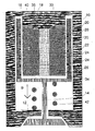
- valve arrangement for a valve controlled Internal combustion engine schematically illustrated in longitudinal section.
- An electric linear motor 10 is used in the invention Valve arrangement as an actuator for a valve member 12.
- the Linear motor 10 has one with the valve member 12 via a Rod 14 coupled rotor 16 and a stand 18th
- the stand 18 is constructed from circular iron sheets 20, whose surface is perpendicular to the direction of movement B of the Runner 16 is oriented.
- the stand 18 faces the rotor 16 facing teeth 22, each having a closed, the Runner 16 have facing surface.
- the individual teeth 22 a circular cylindrical surface.
- oval sheets or sheets with a polygonal shape for Structure of the stand 18 to use.
- the stator 18 has stator windings 24 that are parallel are oriented to the surface of the sheets 20. To do this, some have the sheets 20 have a smaller diameter than those Sheets that form the teeth 22. So that are each between two adjacent teeth 22 open to the outside Winding chambers 26 are formed, in each of which one 18 concentric winding to the central longitudinal axis of the stator 24 is located.
- each of the sheets 20 has a recess 30 in the polymorphic iron material or packed iron wires for magnetic connection of the sheets is included.
- each winding 24 over its entire extent in the Winding chamber is arranged, it also carries over its entire Length for effective force generation in the linear motor at.
- the rotor 16 is a hollow cylindrical one Eisenring, the one on the stand 18 facing Has inner recesses axially spaced from each other, in which copper or aluminum rings 34 are added are.
- the rotor 16 thus works as a hybrid rotor.
- the rotor is on the end face facing away from the valve member 12 16 with a sensor 36 for path detection of the rotor 16 in the direction of movement B coupled.
- the rotor 16 is against the housing 40 with a resonance spring arrangement 42 supported.
Landscapes
- Engineering & Computer Science (AREA)
- Mechanical Engineering (AREA)
- General Engineering & Computer Science (AREA)
- Valve Device For Special Equipments (AREA)
- Magnetically Actuated Valves (AREA)
Abstract
Description
Claims (8)
- Ventilanordnung für einen ventilgesteuerten Verbrennungsmotor, mit einem elektrischen Linearmotor (10) als Aktuator für ein Ventilglied, dereinen mit einem Ventilglied (12) gekoppelten Läufer (16) undeinen Ständer (18) aufweist, wobeider Ständer (18) aus Blechen (20) aufgebaut ist, deren Fläche senkrecht zur Bewegungsrichtung (B) des Läufers (16) orientiert ist, undder Ständer (18) dem Läufer (16) zugewandte Zähne (22) aufweist, die jeweils eine geschlossene, dem Läufer (16) zugewandte Zylindermantelfläche haben, und wobeijeweils zwischen zwei benachbarten Zähnen (22) des Ständers (18) Wicklungskammern (26) gebildet sind, in denen jeweils eine parallel zu der Fläche der Bleche (20) orientierte Wicklung (24) angeordnet ist.
- Ventilanordnung nach Anspruch 1, wobei die Bleche (20) wenigstens eine Ausnehmung (30) aufweisen, die Eisenmaterial zur Verbindung der Bleche (20) enthält.
- Ventilanordnung nach Anspruch 1, wobei die wenigstens eine Wicklung (24) über ihre gesamte Erstreckung zur effektiven Kraftbildung in dem Linearmotor (10) beiträgt.
- Ventilanordnung nach Anspruch 1, wobei der Läufer (16) als Asynchronläufer oder als Synchronläufer, oder als Reluktanzläufer ausgebildet ist.
- Ventilanordnung nach Anspruch 1, wobei der Läufer (16) mit einem Sensor zur Wegerfassung, vorzugsweise einer Tauchspulenanordnung (36) gekoppelt ist.
- Ventilanordnung nach Anspruch 1, wobei der Läufer (16) mit einer Resonanzfederanordnung (42) gekoppelt ist.
- Ventilanordnung nach Anspruch 1, wobei der Läufer als Hybridläufer, mit einem Eisenkörper (16) in den Kupfer- oder Aluminiumreifen (34) eingesetzt sind, ausgestaltet ist.
- Interner Verbrennungsmotor mit wenigstens einem Verbrennungszylinder, mit wenigstens einer Ventilanordnung mit den Merkmalen eines oder mehrerer der vorstehenden Ansprüche.
Applications Claiming Priority (3)
| Application Number | Priority Date | Filing Date | Title |
|---|---|---|---|
| DE19723923 | 1997-06-06 | ||
| DE19723923A DE19723923C2 (de) | 1997-06-06 | 1997-06-06 | Ventilanordnung für einen ventilgesteuerten Verbrennungsmotor |
| PCT/EP1998/003212 WO1998055741A1 (de) | 1997-06-06 | 1998-05-29 | Ventilanordnung für einen ventilgesteuerten verbrennungsmotor |
Publications (2)
| Publication Number | Publication Date |
|---|---|
| EP0986696A1 EP0986696A1 (de) | 2000-03-22 |
| EP0986696B1 true EP0986696B1 (de) | 2002-03-27 |
Family
ID=7831698
Family Applications (1)
| Application Number | Title | Priority Date | Filing Date |
|---|---|---|---|
| EP98928335A Expired - Lifetime EP0986696B1 (de) | 1997-06-06 | 1998-05-29 | Ventilanordnung für einen ventilgesteuerten verbrennungsmotor |
Country Status (4)
| Country | Link |
|---|---|
| EP (1) | EP0986696B1 (de) |
| JP (1) | JP2002506499A (de) |
| DE (2) | DE19723923C2 (de) |
| WO (1) | WO1998055741A1 (de) |
Families Citing this family (13)
| Publication number | Priority date | Publication date | Assignee | Title |
|---|---|---|---|---|
| FR2784712B1 (fr) * | 1998-10-15 | 2001-09-14 | Sagem | Procede et dispositif d'actionnement electromagnetique de soupape |
| DE19910065C1 (de) * | 1999-03-08 | 2000-07-20 | Gruendl & Hoffmann | Verbrennungsmotor mit wenigstens einer Steuerventilanordnung |
| DE19928560C2 (de) * | 1999-06-22 | 2002-02-07 | Bayerische Motoren Werke Ag | Drehmomentregelsystem für Brennkraftmaschinen in Kraftfahrzeugen mit einer Betätigungsvorrichtung zur variablen Ventilsteuerung |
| DE10044789C2 (de) * | 2000-09-11 | 2003-06-12 | Compact Dynamics Gmbh | Antiebsvorrichtung eines Gaswechselventils für einen ventilgesteuerten Verbrennungsmotor |
| DE10035973C2 (de) * | 2000-07-24 | 2003-06-05 | Compact Dynamics Gmbh | Gaswechselventil für einen ventilgesteuerten Verbrennungsmotor |
| EP1445433B1 (de) | 2000-07-24 | 2005-06-15 | Compact Dynamics GmbH | Ventilantrieb für einen ventilgesteuerten Verbrennungsmotor |
| DE10062823A1 (de) * | 2000-12-15 | 2002-07-04 | Bob Bobolowski Gmbh | Mehrphasiger Tauchspulenmotor ohne eigene Lagerung |
| EP1536108A1 (de) * | 2003-11-24 | 2005-06-01 | Siemens Aktiengesellschaft | Linearventilantrieb |
| DE102004042925A1 (de) * | 2004-09-02 | 2006-03-09 | Heinz Leiber | Federnde Aktuatorankopplung |
| DE102005017482B4 (de) | 2005-04-15 | 2007-05-03 | Compact Dynamics Gmbh | Gaswechselventilaktor für einen ventilgesteuerten Verbrennungsmotor |
| DE102005017481B4 (de) | 2005-04-15 | 2007-08-30 | Compact Dynamics Gmbh | Linearaktor |
| DE102005056860A1 (de) * | 2005-11-29 | 2007-05-31 | GM Global Technology Operations, Inc., Detroit | Kraftstoffbehälter |
| CN110656995B (zh) * | 2019-11-08 | 2021-01-15 | 江苏科技大学 | 一种应用于内燃机的复合式电磁驱动全可变配气机构 |
Family Cites Families (8)
| Publication number | Priority date | Publication date | Assignee | Title |
|---|---|---|---|---|
| GB1591421A (en) * | 1977-01-12 | 1981-06-24 | Lucas Industries Ltd | Valve operating mechanism |
| US4533890A (en) * | 1984-12-24 | 1985-08-06 | General Motors Corporation | Permanent magnet bistable solenoid actuator |
| US4810914A (en) * | 1987-03-26 | 1989-03-07 | International Business Machines Corporation | Linear actuator with multiple closed loop flux paths essentially orthogonal to its axis |
| JP2639587B2 (ja) * | 1989-03-30 | 1997-08-13 | 株式会社いすゞセラミックス研究所 | バルブのステッピング駆動装置 |
| JP2709742B2 (ja) * | 1989-12-20 | 1998-02-04 | 株式会社いすゞセラミックス研究所 | 電磁力バルブ駆動装置 |
| JPH04175408A (ja) * | 1990-11-08 | 1992-06-23 | Isuzu Ceramics Kenkyusho:Kk | 電磁力バルブ駆動装置 |
| DE19518056B4 (de) * | 1995-05-17 | 2005-04-07 | Fev Motorentechnik Gmbh | Einrichtung zur Steuerung der Ankerbewegung einer elektromagnetischen Schaltanordnung und Verfahren zur Ansteuerung |
| DE19722632A1 (de) * | 1997-05-30 | 1998-12-03 | Schaeffler Waelzlager Ohg | Antrieb zur periodischen Beaufschlagung wenigstens eines Ventils |
-
1997
- 1997-06-06 DE DE19723923A patent/DE19723923C2/de not_active Expired - Fee Related
-
1998
- 1998-05-29 DE DE59803523T patent/DE59803523D1/de not_active Expired - Fee Related
- 1998-05-29 WO PCT/EP1998/003212 patent/WO1998055741A1/de not_active Ceased
- 1998-05-29 JP JP50144999A patent/JP2002506499A/ja active Pending
- 1998-05-29 EP EP98928335A patent/EP0986696B1/de not_active Expired - Lifetime
Also Published As
| Publication number | Publication date |
|---|---|
| DE19723923C2 (de) | 2000-06-21 |
| DE59803523D1 (de) | 2002-05-02 |
| JP2002506499A (ja) | 2002-02-26 |
| DE19723923A1 (de) | 1998-12-10 |
| EP0986696A1 (de) | 2000-03-22 |
| WO1998055741A1 (de) | 1998-12-10 |
Similar Documents
| Publication | Publication Date | Title |
|---|---|---|
| EP0986696B1 (de) | Ventilanordnung für einen ventilgesteuerten verbrennungsmotor | |
| DE602004012340T2 (de) | Turbolader mit elektrischem Hilfsantrieb | |
| DE69609254T2 (de) | Vorrichtung zur betätigung eines steuerelements | |
| EP0450288B1 (de) | Elektrischer Linearmotor | |
| WO2007036202A1 (de) | Strahltriebwerk mit einer integrierten elektrischen motor/generatoreinheit | |
| DE102008041180A1 (de) | Stirling-Kreislaufmaschine | |
| EP1445432B1 (de) | Ventilantrieb für einen ventilgesteuerten Verbrennungsmotor | |
| WO2003061099A2 (de) | Verbrennungsmotor mit in einem kurbelgehäuse gelagerter kurbelwelle, wobei der starter/generator auf der kurbelwelle angeordnet ist | |
| WO2008145640A1 (de) | Elektromagnetischer abgasturbolader | |
| DE10044789C2 (de) | Antiebsvorrichtung eines Gaswechselventils für einen ventilgesteuerten Verbrennungsmotor | |
| EP1263122A1 (de) | Rotationssymmetrischer Linearantrieb mit doppelseitiger Aktuatoranordnung | |
| DE19910065C1 (de) | Verbrennungsmotor mit wenigstens einer Steuerventilanordnung | |
| EP2291903B1 (de) | Linearstellantrieb, insbesondere zum verstellen der klappen in kfz-turboladern | |
| DE10035973C2 (de) | Gaswechselventil für einen ventilgesteuerten Verbrennungsmotor | |
| DE10125767C1 (de) | Gaswechselventilantrieb für einen ventilgesteuerten Verbrennungsmotor | |
| DE102005017482B4 (de) | Gaswechselventilaktor für einen ventilgesteuerten Verbrennungsmotor | |
| DE102022122783A1 (de) | Rotor mit dauermagneten für eine drehende elektrische maschine | |
| EP1869756B1 (de) | Linearaktor | |
| DE4445100C2 (de) | Schaltbares Drosselklappensystem | |
| WO1998056098A1 (de) | Linearmotor | |
| DE102016220865A1 (de) | Medienspaltmotor, Verdichter oder Turbine, Abgasturbolader | |
| DE102011117477A1 (de) | Elektrische Maschine an zumindest einer Zylinderlaufbuchse einer Verbrennungskraftmaschine und Verfahren zu deren Betrieb | |
| DE102022100699A1 (de) | Stator, elektrische Maschine und Verfahren zur Herstellung eines Stators | |
| DE112016006440T5 (de) | Magnetelektrischer Motor, Generator oder Anlasser | |
| DE1638418C3 (de) | Hystereseläufer mit einer Käfigwicklung |
Legal Events
| Date | Code | Title | Description |
|---|---|---|---|
| PUAI | Public reference made under article 153(3) epc to a published international application that has entered the european phase |
Free format text: ORIGINAL CODE: 0009012 |
|
| 17P | Request for examination filed |
Effective date: 19991110 |
|
| AK | Designated contracting states |
Kind code of ref document: A1 Designated state(s): DE ES FR GB IT |
|
| RAP1 | Party data changed (applicant data changed or rights of an application transferred) |
Owner name: ISAD ELECTRONIC SYSTEMS GMBH & CO.KG Owner name: BAYERISCHE MOTOREN WERKE AKTIENGESELLSCHAFT Owner name: CONTINENTAL ISAD ELECTRONIC SYSTEMS GMBH & CO. OHG |
|
| GRAG | Despatch of communication of intention to grant |
Free format text: ORIGINAL CODE: EPIDOS AGRA |
|
| 17Q | First examination report despatched |
Effective date: 20010525 |
|
| GRAG | Despatch of communication of intention to grant |
Free format text: ORIGINAL CODE: EPIDOS AGRA |
|
| GRAH | Despatch of communication of intention to grant a patent |
Free format text: ORIGINAL CODE: EPIDOS IGRA |
|
| RAP1 | Party data changed (applicant data changed or rights of an application transferred) |
Owner name: BAYERISCHE MOTOREN WERKE AKTIENGESELLSCHAFT Owner name: CONTINENTAL ISAD ELECTRONIC SYSTEMS GMBH & CO. OHG |
|
| GRAH | Despatch of communication of intention to grant a patent |
Free format text: ORIGINAL CODE: EPIDOS IGRA |
|
| REG | Reference to a national code |
Ref country code: GB Ref legal event code: IF02 |
|
| GRAA | (expected) grant |
Free format text: ORIGINAL CODE: 0009210 |
|
| AK | Designated contracting states |
Kind code of ref document: B1 Designated state(s): DE ES FR GB IT |
|
| PG25 | Lapsed in a contracting state [announced via postgrant information from national office to epo] |
Ref country code: IT Free format text: LAPSE BECAUSE OF FAILURE TO SUBMIT A TRANSLATION OF THE DESCRIPTION OR TO PAY THE FEE WITHIN THE PRESCRIBED TIME-LIMIT;WARNING: LAPSES OF ITALIAN PATENTS WITH EFFECTIVE DATE BEFORE 2007 MAY HAVE OCCURRED AT ANY TIME BEFORE 2007. THE CORRECT EFFECTIVE DATE MAY BE DIFFERENT FROM THE ONE RECORDED. Effective date: 20020327 Ref country code: GB Free format text: LAPSE BECAUSE OF FAILURE TO SUBMIT A TRANSLATION OF THE DESCRIPTION OR TO PAY THE FEE WITHIN THE PRESCRIBED TIME-LIMIT Effective date: 20020327 Ref country code: FR Free format text: LAPSE BECAUSE OF FAILURE TO SUBMIT A TRANSLATION OF THE DESCRIPTION OR TO PAY THE FEE WITHIN THE PRESCRIBED TIME-LIMIT Effective date: 20020327 |
|
| REF | Corresponds to: |
Ref document number: 59803523 Country of ref document: DE Date of ref document: 20020502 |
|
| GBV | Gb: ep patent (uk) treated as always having been void in accordance with gb section 77(7)/1977 [no translation filed] |
Effective date: 20020327 |
|
| PG25 | Lapsed in a contracting state [announced via postgrant information from national office to epo] |
Ref country code: ES Free format text: LAPSE BECAUSE OF FAILURE TO SUBMIT A TRANSLATION OF THE DESCRIPTION OR TO PAY THE FEE WITHIN THE PRESCRIBED TIME-LIMIT Effective date: 20020925 |
|
| EN | Fr: translation not filed | ||
| PLBE | No opposition filed within time limit |
Free format text: ORIGINAL CODE: 0009261 |
|
| STAA | Information on the status of an ep patent application or granted ep patent |
Free format text: STATUS: NO OPPOSITION FILED WITHIN TIME LIMIT |
|
| 26N | No opposition filed |
Effective date: 20021230 |
|
| PGFP | Annual fee paid to national office [announced via postgrant information from national office to epo] |
Ref country code: DE Payment date: 20060711 Year of fee payment: 9 |
|
| PG25 | Lapsed in a contracting state [announced via postgrant information from national office to epo] |
Ref country code: DE Free format text: LAPSE BECAUSE OF NON-PAYMENT OF DUE FEES Effective date: 20071201 |