EP0986847B1 - Laser a l'etat solide comprenant au moins une source de lumiere de pompage - Google Patents
Laser a l'etat solide comprenant au moins une source de lumiere de pompage Download PDFInfo
- Publication number
- EP0986847B1 EP0986847B1 EP98934809A EP98934809A EP0986847B1 EP 0986847 B1 EP0986847 B1 EP 0986847B1 EP 98934809 A EP98934809 A EP 98934809A EP 98934809 A EP98934809 A EP 98934809A EP 0986847 B1 EP0986847 B1 EP 0986847B1
- Authority
- EP
- European Patent Office
- Prior art keywords
- laser
- solid state
- pump light
- optical waveguide
- state laser
- Prior art date
- Legal status (The legal status is an assumption and is not a legal conclusion. Google has not performed a legal analysis and makes no representation as to the accuracy of the status listed.)
- Expired - Lifetime
Links
- 239000007787 solid Substances 0.000 title claims abstract description 13
- 239000013078 crystal Substances 0.000 claims abstract description 24
- 230000003287 optical effect Effects 0.000 claims abstract description 16
- 230000001681 protective effect Effects 0.000 claims description 5
- 230000001419 dependent effect Effects 0.000 claims 1
- 230000005855 radiation Effects 0.000 abstract 1
- 239000000835 fiber Substances 0.000 description 15
- 239000013307 optical fiber Substances 0.000 description 10
- 238000004519 manufacturing process Methods 0.000 description 5
- 230000008878 coupling Effects 0.000 description 4
- 238000010168 coupling process Methods 0.000 description 4
- 238000005859 coupling reaction Methods 0.000 description 4
- 230000010287 polarization Effects 0.000 description 3
- 238000007789 sealing Methods 0.000 description 3
- 241000219739 Lens Species 0.000 description 2
- 239000011248 coating agent Substances 0.000 description 2
- 238000000576 coating method Methods 0.000 description 2
- RYGMFSIKBFXOCR-UHFFFAOYSA-N Copper Chemical compound [Cu] RYGMFSIKBFXOCR-UHFFFAOYSA-N 0.000 description 1
- 240000004322 Lens culinaris Species 0.000 description 1
- 230000005540 biological transmission Effects 0.000 description 1
- 230000003749 cleanliness Effects 0.000 description 1
- 238000001816 cooling Methods 0.000 description 1
- 229910052802 copper Inorganic materials 0.000 description 1
- 239000010949 copper Substances 0.000 description 1
- 238000011161 development Methods 0.000 description 1
- 230000018109 developmental process Effects 0.000 description 1
- 239000000463 material Substances 0.000 description 1
- 239000002184 metal Substances 0.000 description 1
- 229910052751 metal Inorganic materials 0.000 description 1
- 238000005086 pumping Methods 0.000 description 1
Images



Classifications
-
- H—ELECTRICITY
- H01—ELECTRIC ELEMENTS
- H01S—DEVICES USING THE PROCESS OF LIGHT AMPLIFICATION BY STIMULATED EMISSION OF RADIATION [LASER] TO AMPLIFY OR GENERATE LIGHT; DEVICES USING STIMULATED EMISSION OF ELECTROMAGNETIC RADIATION IN WAVE RANGES OTHER THAN OPTICAL
- H01S3/00—Lasers, i.e. devices using stimulated emission of electromagnetic radiation in the infrared, visible or ultraviolet wave range
- H01S3/09—Processes or apparatus for excitation, e.g. pumping
- H01S3/091—Processes or apparatus for excitation, e.g. pumping using optical pumping
- H01S3/094—Processes or apparatus for excitation, e.g. pumping using optical pumping by coherent light
- H01S3/0941—Processes or apparatus for excitation, e.g. pumping using optical pumping by coherent light of a laser diode
- H01S3/09415—Processes or apparatus for excitation, e.g. pumping using optical pumping by coherent light of a laser diode the pumping beam being parallel to the lasing mode of the pumped medium, e.g. end-pumping
-
- H—ELECTRICITY
- H01—ELECTRIC ELEMENTS
- H01S—DEVICES USING THE PROCESS OF LIGHT AMPLIFICATION BY STIMULATED EMISSION OF RADIATION [LASER] TO AMPLIFY OR GENERATE LIGHT; DEVICES USING STIMULATED EMISSION OF ELECTROMAGNETIC RADIATION IN WAVE RANGES OTHER THAN OPTICAL
- H01S3/00—Lasers, i.e. devices using stimulated emission of electromagnetic radiation in the infrared, visible or ultraviolet wave range
- H01S3/02—Constructional details
- H01S3/025—Constructional details of solid state lasers, e.g. housings or mountings
-
- H—ELECTRICITY
- H01—ELECTRIC ELEMENTS
- H01S—DEVICES USING THE PROCESS OF LIGHT AMPLIFICATION BY STIMULATED EMISSION OF RADIATION [LASER] TO AMPLIFY OR GENERATE LIGHT; DEVICES USING STIMULATED EMISSION OF ELECTROMAGNETIC RADIATION IN WAVE RANGES OTHER THAN OPTICAL
- H01S3/00—Lasers, i.e. devices using stimulated emission of electromagnetic radiation in the infrared, visible or ultraviolet wave range
- H01S3/09—Processes or apparatus for excitation, e.g. pumping
- H01S3/091—Processes or apparatus for excitation, e.g. pumping using optical pumping
- H01S3/094—Processes or apparatus for excitation, e.g. pumping using optical pumping by coherent light
- H01S3/094049—Guiding of the pump light
- H01S3/094053—Fibre coupled pump, e.g. delivering pump light using a fibre or a fibre bundle
-
- H—ELECTRICITY
- H01—ELECTRIC ELEMENTS
- H01S—DEVICES USING THE PROCESS OF LIGHT AMPLIFICATION BY STIMULATED EMISSION OF RADIATION [LASER] TO AMPLIFY OR GENERATE LIGHT; DEVICES USING STIMULATED EMISSION OF ELECTROMAGNETIC RADIATION IN WAVE RANGES OTHER THAN OPTICAL
- H01S3/00—Lasers, i.e. devices using stimulated emission of electromagnetic radiation in the infrared, visible or ultraviolet wave range
- H01S3/09—Processes or apparatus for excitation, e.g. pumping
- H01S3/091—Processes or apparatus for excitation, e.g. pumping using optical pumping
- H01S3/094—Processes or apparatus for excitation, e.g. pumping using optical pumping by coherent light
- H01S3/094096—Multi-wavelength pumping
Definitions
- the invention relates to a solid-state laser according to the preamble of the claim 1.
- US Pat. No. 5,127,068 describes an arrangement for coupling a multi-emitter laser diode to a multimode optical fiber, in which each emitter emits the pump light onto the laser crystal via an optical fiber.
- the disadvantage here is that, owing to the large fiber bundle diameter, only a low luminance is achieved on the laser crystal and the efficiency of the laser arrangement thus remains low.
- Another disadvantage of this arrangement is the complex and complicated coupling of the individual optical fibers to the emitters.
- the power density is relatively low because the fibers cannot be packed tightly enough and each fiber can only absorb the power of one emitter. The power density is about 1 KW / cm 2 .
- FIGS. 28 and 29 together with the associated description, describes a laser amplifier system in which a laser crystal by means of a multiple mirror arrangement is pumped over a fiber bundle.
- the above-described disadvantage of the fiber bundle is a multi-mirror arrangement required in the pump beam path of the laser, which is complex and is complicated to manufacture. Such an arrangement is also in production difficult to manufacture with sufficient cleanliness and in operation against pollution to protect. This results in a short lifespan, in particular at high performances.
- US-A-5 608 742 also discloses a solid state laser genus mentioned at the beginning.
- the object of the invention is to produce laser arrangements that are simple to manufacture and more cost-effective with high output, high efficiency and long Manufacture life.
- Fig. 1 shows an embodiment of the invention in which a laser diode unit (1), which serves as a pump light source, an optical waveguide (2), which here as Individual fiber is shown, is connected to a laser resonator (3).
- the laser diode unit (1) is housed in a hermetically sealed housing (11), one end of the optical waveguide (2) being detachable Plug connections (21) which have a seal (22) to the laser diode unit (1) is connected.
- the other end of the optical fiber (2) is with the laser resonator (3) also via a detachable plug connection (31) has a seal (32) connected.
- the housing (11) can be advantageous Evacuated or filled with a protective gas.
- the laser diode unit (1) consists of a laser diode array (12) which is powered by a power supply (13) becomes.
- the light emerging from the laser diodes is converted by means of a Stair mirror arrangement (14) and an optical system (15) in the optical waveguide (2) coupled.
- a Stair mirror arrangement is for example in the DE 44 38 368 describes and has the advantage, among other things, that it is special can be produced inexpensively and only, as has been shown, low Adjustment wall required.
- the optical fiber (2) is efficient Coupling the laser diode energy as a single fiber with a small diameter educated.
- the laser resonator preferably consists of a tubular housing (33), at one end of which the optical waveguide (2) is connected.
- the Light from the optical waveguide (2) is applied to a laser crystal via optics (34) (35) steered, whereby between the optics (34) and the laser crystal (35) first laser mirror (36) is located.
- a corrugated Pipe (37) placed on the end of a second adjustable mirror (38) is attached.
- the mirror can be soldered or glued.
- the pipe is corrugated so that the mirror (38) can be adjusted.
- the two mirrors (36) and (38) form the laser resonator, which is adjusted by adjusting the mirror (38) the resonance frequency of the laser light emerging from the laser crystal (35) is voted.
- the mirror (36) has on its, the optics (34) facing Side on a coating that the light of the wavelength ⁇ l of the laser light is reflected and transmissive to the wavelength of the pump light ⁇ p.
- the other side of the mirror (36) is coated so that both the pump light, as the laser light is let through.
- the mirror (38) is designed that it allows partial reflection of the laser light emerging from it.
- FIGS. 2a and 2b show possible embodiments of the optical fibers shown, which can be used as an optical waveguide (2).
- 2a is a fiber (4) with a round core (41), a jacket (42) and a protective cover (43) and in Fig. 2b a fiber (5) with a rectangular core (51), a jacket (5329 and a protective cover (53).
- the advantage of the rectangular Cross-section is that the cross-section is optimal to the Individual emitter can be adapted
- the rectangular core can preferably 300 to 330 ⁇ m X 100 to 170 ⁇ m edge length. With a round core the diameter is also in the range of 100 to 330 microns.
- 2a and 2b can be a Diode power of approx. 20 W can be coupled into the laser crystal (35).
- FIG. 3 Another embodiment for increasing the pump power is shown in FIG. 3.
- two pump light sources are to be coupled into a single fiber become.
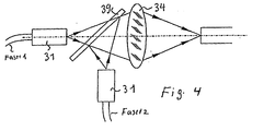
- FIG. 4 shows a further arrangement for increasing the pump power, where two pump light sources via polarization-maintaining optical fibers and an arrangement comparable to FIG. 3 can be merged.
- the light emerging from fiber 1 may be polarized vertically and that light emerging from the fiber 2 must be horizontally polarized.
- the mirror 39 ' should be permeable for vertical polarization and for horizontal polarization be reflective. Then the light of the two light sources either as in Fig. 3 via the mirror (36) onto the laser crystal (35) or as shown in Fig. 4, passed into a single waveguide.
- FIG. 5 shows a further embodiment of a laser resonator with a tubular housing (7), in which the resonator chamber is hermetically sealed is a mirrored laser crystal (71) which is designed as a disk is by means of two pump light sources (72) and (73), their plug connections (721) and (723) by means of sealing rings (724) and (725) with the housing (7) are excited.
- the pump light is switched on via the two optics (74) and (75) directed onto the laser crystal (71).
- the first laser mirror (711) is designed so that it is for the wavelength of the pump light ⁇ p reflective and for the wavelength of the laser light ⁇ L is permeable.
- the second laser mirror (712) is at the other end of the cavity and is over one corrugated metal bellows (77) adjustable.
- FIG. 6 shows an arrangement (8) for sealing a pump light source, in which the sealing by means of a lens (81) and a ring seal (82) is made.
- the two pumping light sources of FIG. 7 could, for example be sealed in this way.
- FIG. 7 shows a further embodiment of a laser resonator with a tubular one Shown housing (9), in which also a disk-shaped mirrored Laser crystal (91) is used.
- the nature of the mirror surface (911), through which the pump light enters is chosen so that it for the wavelength of Pump light ⁇ p permeable (transmission) and for the wavelength of the laser light ⁇ L is reflective.
- the mirror surface (912), on the inside of the resonator is designed so that it is for the wavelength of the pump light ⁇ p is reflective and transparent to the wavelength of the laser light ⁇ L.
- the tubular housing (9) can, if the laser is cooled with air, with cooling fins (92) can be provided.
- a Brewster plate (93) may be provided.
- the housing (9) should be made of good thermal conductivity Material, for example copper.
- the interior of the Resonator can advantageously be filled with protective gas.
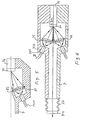
- FIG 8 shows a section from another embodiment of a laser resonator shown with a tubular housing (10), in which a rod-shaped mirrored laser crystal (101) is used.
- the nature of the mirror surface (102) through which the pump light enters is chosen so that it is suitable for the Wavelength of the pump light ⁇ p transmissive and for the wavelength of the laser light ⁇ L is reflective (reflection).
- the mirror surface (103), on the inside of the resonator is ⁇ L for the wavelength of the laser light non-reflective.
Landscapes
- Physics & Mathematics (AREA)
- Electromagnetism (AREA)
- Engineering & Computer Science (AREA)
- Plasma & Fusion (AREA)
- Optics & Photonics (AREA)
- Lasers (AREA)
Abstract
Claims (10)
- Laser solide composé d'au moins une source lumineuse de pompage (1) à plusieurs diodes laser (12) et d'un résonateur optique laser (3) avec un cristal de laser (35), dans lequel
la lumière générée par les diodes laser (12) est couplée dans le cristal (35) et, pour créer une forte densité de lumière de la lumière laser injectée dans le cristal (35), on connecte en aval des diodes laser (12) de la source de pompage de lumière (1), un dispositif à plusieurs miroirs (14) ainsi qu'une optique (15) pour coupler la lumière sortant des diodes laser (12) avec une densité d'éclairage élevée pour passer dans un guide de lumière (2) distinct,
caractérisé en ce que
le dispositif à plusieurs miroirs (14) est réalisé sous la forme d'un dispositif à miroirs en gradin, connu en soi,
au moins deux sources de pompage de lumière (1) pour de la lumière laser polarisée avec une polarité différente, sont prévues,
la lumière laser transportée par les guides d'ondes (2) associés aux sources de pompage de lumière (1), est regroupée par un miroir semi-transparent (39), dépendant de la polarisation, pour augmenter encore la densité de lumière, et
la lumière laser regroupée est injectée par une optique (34) dans le cristal de laser (35) ou dans un autre guide d'ondes. - Laser solide selon la revendication 1,
caractérisé en ce que
le résonateur laser (3) est fermé de manière hermétique. - Laser solide selon la revendication 1,
caractérisé en ce que
le résonateur laser (3) est sous vide. - Laser solide selon la revendication 2,
caractérisé en ce que
le résonateur laser (3) est rempli d'un gaz protecteur. - Laser solide selon les revendications 1 à 4,
caractérisé en ce que
le guide de lumière (2) a une section ronde. - Laser solide selon les revendications 1 à 4,
caractérisé en ce que
le guide de lumière (2) a une section elliptique. - Laser solide selon l'une des revendications 1 à 4,
caractérisé en ce que
le guide de lumière (2) a une section carrée. - Laser solide selon l'une des revendications 1 à 4,
caractérisé en ce que
le guide de lumière (2) a une section rectangulaire. - Laser solide selon la revendication 8,
caractérisé en ce que
le guide de lumière (2) comporte des connexions amovibles (31, 32) à au moins une extrémité. - Laser solide selon l'une des revendications 1 à 9,
caractérisé en ce que
le résonateur laser (3) comporte des miroirs laser (36, 38) et au moins un cristal laser (35) est prévu directement sur l'un des miroirs laser (36, 38).
Applications Claiming Priority (3)
| Application Number | Priority Date | Filing Date | Title |
|---|---|---|---|
| DE19723269 | 1997-06-03 | ||
| DE19723269A DE19723269A1 (de) | 1997-06-03 | 1997-06-03 | Festkörperlaser mit einer oder mehreren Pumplichtquellen |
| PCT/DE1998/001448 WO1998056086A1 (fr) | 1997-06-03 | 1998-05-27 | Laser a solide comportant une ou plusieurs sources de lumiere de pompage |
Publications (2)
| Publication Number | Publication Date |
|---|---|
| EP0986847A1 EP0986847A1 (fr) | 2000-03-22 |
| EP0986847B1 true EP0986847B1 (fr) | 2003-05-14 |
Family
ID=7831277
Family Applications (1)
| Application Number | Title | Priority Date | Filing Date |
|---|---|---|---|
| EP98934809A Expired - Lifetime EP0986847B1 (fr) | 1997-06-03 | 1998-05-27 | Laser a l'etat solide comprenant au moins une source de lumiere de pompage |
Country Status (5)
| Country | Link |
|---|---|
| US (1) | US6434177B1 (fr) |
| EP (1) | EP0986847B1 (fr) |
| JP (1) | JP2000513156A (fr) |
| DE (2) | DE19723269A1 (fr) |
| WO (1) | WO1998056086A1 (fr) |
Families Citing this family (24)
| Publication number | Priority date | Publication date | Assignee | Title |
|---|---|---|---|---|
| DE10241983A1 (de) * | 2002-09-11 | 2004-03-25 | Tui Laser Ag | Festkörperlasersystem mit Gehäuse sowie Verfahren zur Montage |
| JP2005039093A (ja) * | 2003-07-16 | 2005-02-10 | Okazaki National Research Institutes | レーザ装置 |
| FR2863916B1 (fr) * | 2003-12-19 | 2007-04-27 | Commissariat Energie Atomique | Procede et dispositif de nettoyage d'une surface au moyen d'un faisceau laser |
| CN100476794C (zh) * | 2004-06-09 | 2009-04-08 | 中国科学院计算技术研究所 | 一种四路服务器主板 |
| US7346091B2 (en) * | 2005-01-12 | 2008-03-18 | Raytheon Company | High energy solid-state laser with offset pump and extraction geometry |
| US8031749B2 (en) * | 2005-09-20 | 2011-10-04 | Jds Uniphase Corporation | Passively Q-switched microlaser with controllable peak power density |
| WO2010028346A1 (fr) * | 2008-09-05 | 2010-03-11 | Ams Research Corporation | Système laser possédant des modes de puissance pouvant être commutés |
| US9001862B2 (en) * | 2012-03-09 | 2015-04-07 | Raytheon Company | Miniaturized solid-state lasing device, system and method |
| US10069271B2 (en) | 2014-06-02 | 2018-09-04 | Nlight, Inc. | Scalable high power fiber laser |
| US10310201B2 (en) | 2014-08-01 | 2019-06-04 | Nlight, Inc. | Back-reflection protection and monitoring in fiber and fiber-delivered lasers |
| US9634462B2 (en) | 2014-10-15 | 2017-04-25 | Nlight, Inc. | Slanted FBG for SRS suppression |
| US9837783B2 (en) | 2015-01-26 | 2017-12-05 | Nlight, Inc. | High-power, single-mode fiber sources |
| US10050404B2 (en) | 2015-03-26 | 2018-08-14 | Nlight, Inc. | Fiber source with cascaded gain stages and/or multimode delivery fiber with low splice loss |
| WO2017008022A1 (fr) | 2015-07-08 | 2017-01-12 | Nlight, Inc. | Fibre dotée d'un indice central en creux destinée à un produit à paramètre augmenté |
| WO2017053985A1 (fr) | 2015-09-24 | 2017-03-30 | Nlight, Inc. | Contrôle du produit des paramètres de faisceau (bpp) en faisant varier un angle entre des fibres |
| US11179807B2 (en) | 2015-11-23 | 2021-11-23 | Nlight, Inc. | Fine-scale temporal control for laser material processing |
| US10434600B2 (en) | 2015-11-23 | 2019-10-08 | Nlight, Inc. | Fine-scale temporal control for laser material processing |
| US10732439B2 (en) | 2016-09-29 | 2020-08-04 | Nlight, Inc. | Fiber-coupled device for varying beam characteristics |
| US10673199B2 (en) | 2016-09-29 | 2020-06-02 | Nlight, Inc. | Fiber-based saturable absorber |
| US10730785B2 (en) | 2016-09-29 | 2020-08-04 | Nlight, Inc. | Optical fiber bending mechanisms |
| US10295845B2 (en) | 2016-09-29 | 2019-05-21 | Nlight, Inc. | Adjustable beam characteristics |
| US10673198B2 (en) | 2016-09-29 | 2020-06-02 | Nlight, Inc. | Fiber-coupled laser with time varying beam characteristics |
| US10673197B2 (en) | 2016-09-29 | 2020-06-02 | Nlight, Inc. | Fiber-based optical modulator |
| US10998689B2 (en) * | 2018-01-19 | 2021-05-04 | Shailendhar Saraf | Systems, apparatus, and methods for producing ultra stable, single-frequency, single-transverse-mode coherent light in solid-state lasers |
Family Cites Families (26)
| Publication number | Priority date | Publication date | Assignee | Title |
|---|---|---|---|---|
| US4273257A (en) * | 1977-07-18 | 1981-06-16 | Sherwood Medical Industries Inc. | Jar mounted pipettor |
| US4383318A (en) * | 1980-12-15 | 1983-05-10 | Hughes Aircraft Company | Laser pumping system |
| US4723257A (en) * | 1986-05-19 | 1988-02-02 | Spectra-Physics, Inc. | Laser diode pumped solid state laser with miniaturized laser head |
| USRE33722E (en) * | 1987-04-28 | 1991-10-22 | Spectra Diode Laboratories, Inc. | Optical system with bright light output |
| JPH01133007A (ja) * | 1987-11-18 | 1989-05-25 | Nippon Telegr & Teleph Corp <Ntt> | 光ファイバ |
| DE3943722C2 (de) * | 1988-02-10 | 1996-01-18 | Mitsubishi Electric Corp | Anordnung zum optischen Pumpen eines Lasermediums |
| WO1990016099A1 (fr) * | 1989-06-14 | 1990-12-27 | Australian Electro Optics Pty Ltd | Laser a semi-conducteurs couple par un faisceau de fibres optiques, pompe par des diodes, refroidi par un fluide et optiquement commute |
| US5022043A (en) * | 1989-12-20 | 1991-06-04 | Spectra-Physics | High power diode-pumped solid state laser with unstable resonator |
| GB2239733A (en) * | 1990-01-03 | 1991-07-10 | British Telecomm | A laser oscillator |
| US5127068A (en) * | 1990-11-16 | 1992-06-30 | Spectra-Physics, Inc. | Apparatus for coupling a multiple emitter laser diode to a multimode optical fiber |
| JPH05145150A (ja) * | 1991-11-19 | 1993-06-11 | Sony Corp | 固体レーザ |
| JP2849032B2 (ja) * | 1992-11-02 | 1999-01-20 | 三菱電機株式会社 | レーザ装置 |
| US5450244A (en) * | 1992-12-18 | 1995-09-12 | Polaroid Corporation | Cylindrical fiber coupling lens with biaspheric surfaces |
| US5268978A (en) * | 1992-12-18 | 1993-12-07 | Polaroid Corporation | Optical fiber laser and geometric coupler |
| JPH06268299A (ja) | 1993-03-11 | 1994-09-22 | Olympus Optical Co Ltd | レーザ用励起光源 |
| JPH07135361A (ja) * | 1993-11-10 | 1995-05-23 | Laser Noshuku Gijutsu Kenkyu Kumiai | ファイバー伝送励起型レーザー装置 |
| DE4415269A1 (de) * | 1994-04-30 | 1995-11-02 | Zeiss Carl Fa | Laseranordnung mit einem axial optisch gepumpten Laser |
| US5418880A (en) | 1994-07-29 | 1995-05-23 | Polaroid Corporation | High-power optical fiber amplifier or laser device |
| DE4438368C3 (de) * | 1994-10-27 | 2003-12-04 | Fraunhofer Ges Forschung | Anordnung zur Führung und Formung von Strahlen eines geradlinigen Laserdiodenarrays |
| EP0723323B1 (fr) * | 1994-12-22 | 2002-03-27 | CeramOptec GmbH | Système laser de puissance à haute densité |
| DE19601991A1 (de) * | 1995-01-31 | 1996-08-01 | Zeiss Carl Fa | Laser-Anordung und Verfahren zum Betrieb einer derartigen Laser-Anordnung |
| DE19603704B4 (de) * | 1995-02-15 | 2009-04-09 | Carl Zeiss | Optisch gepumpter Laser mit polarisationsabhängiger Absorption |
| US5608742A (en) * | 1995-08-18 | 1997-03-04 | Spectra Physics Lasers, Inc. | Diode pumped, fiber coupled laser with depolarized pump beam |
| US5663979A (en) * | 1995-11-22 | 1997-09-02 | Light Solutions Corporation | Fiber stub end-pumped laser |
| FR2741726B1 (fr) * | 1995-11-23 | 1997-12-19 | Thomson Csf | Dispositif de mise en forme du faisceau optique |
| US5999554A (en) * | 1996-11-22 | 1999-12-07 | Light Solutions Corporation | Fiber stub end-pumped laser |
-
1997
- 1997-06-03 DE DE19723269A patent/DE19723269A1/de not_active Withdrawn
-
1998
- 1998-05-27 US US09/445,068 patent/US6434177B1/en not_active Expired - Fee Related
- 1998-05-27 DE DE59808372T patent/DE59808372D1/de not_active Expired - Fee Related
- 1998-05-27 EP EP98934809A patent/EP0986847B1/fr not_active Expired - Lifetime
- 1998-05-27 WO PCT/DE1998/001448 patent/WO1998056086A1/fr not_active Ceased
- 1998-05-27 JP JP11501272A patent/JP2000513156A/ja active Pending
Also Published As
| Publication number | Publication date |
|---|---|
| EP0986847A1 (fr) | 2000-03-22 |
| DE59808372D1 (de) | 2003-06-18 |
| US6434177B1 (en) | 2002-08-13 |
| WO1998056086A1 (fr) | 1998-12-10 |
| JP2000513156A (ja) | 2000-10-03 |
| DE19723269A1 (de) | 1998-12-10 |
Similar Documents
| Publication | Publication Date | Title |
|---|---|---|
| WO1998056086A1 (fr) | Laser a solide comportant une ou plusieurs sources de lumiere de pompage | |
| DE3614401C2 (de) | Laserdiodengepumpter Festkörper-Laser | |
| DE69002874T2 (de) | Laser-Dioden-gepumpter Leistungs-Laser. | |
| DE69606664T2 (de) | Optische gepumpter Festkörperlaserkopf | |
| DE69736133T2 (de) | Direktes hochleistungslaserdiodensystem mit hoher effizienz und zugehörende verfahren | |
| DE69731148T2 (de) | Festkörperlaserverstärker | |
| DE68915421T2 (de) | Optisch gepumpter Stablaser mit schmaler Pumpquellen-Emissionsfläche. | |
| DE69014068T2 (de) | Laserdiodengepumpte, integrierende Laservorrichtung. | |
| DE68908707T2 (de) | Transversal einmodiger, auf stoss an die pump-diode gekoppelter laser. | |
| DE4234342C2 (de) | Verfahren zur Materialbearbeitung mit Laserstrahlung | |
| DE2522032C2 (de) | Vorrichtung zum Ausrichten der reflektierenden Oberflächen eines instabilen Laserresonators | |
| DE69507358T2 (de) | Verbesserter CO2 Bandleiterlaser | |
| DE69900478T2 (de) | Hochleistungs-Festkörperlaser in zylindrischem Gehäuse | |
| DE102013102880B4 (de) | Laseranordnung | |
| EP2041847A2 (fr) | Laser à solide avec résonateur monolithique | |
| DE69811929T2 (de) | Diodengepumpter laser unter verwendung von verstärkungsmedia mit starker thermaler fokussierung | |
| DE69617938T2 (de) | Diodengepumpter laser mit kristallen mit starker thermaler fokussierung | |
| DE4090197C2 (de) | Festkörperlaservorrichtung | |
| DE4191708C1 (de) | Festkörperlaser | |
| DE2940149A1 (de) | Wellenleiterverstaerker | |
| DE2456913A1 (de) | Farbstoff-laser | |
| DE19927054A1 (de) | Festkörperlaser | |
| EP0879494B1 (fr) | Amplificateur pompe de maniere optique, notamment amplificateur a l'etat solide | |
| EP0770275B1 (fr) | Laser a solide de haute puissance a pompage par diodes | |
| DE69204131T2 (de) | Festkörperlaser. |
Legal Events
| Date | Code | Title | Description |
|---|---|---|---|
| PUAI | Public reference made under article 153(3) epc to a published international application that has entered the european phase |
Free format text: ORIGINAL CODE: 0009012 |
|
| 17P | Request for examination filed |
Effective date: 20000105 |
|
| AK | Designated contracting states |
Kind code of ref document: A1 Designated state(s): DE FR GB |
|
| 17Q | First examination report despatched |
Effective date: 20000831 |
|
| GRAH | Despatch of communication of intention to grant a patent |
Free format text: ORIGINAL CODE: EPIDOS IGRA |
|
| RTI1 | Title (correction) |
Free format text: SOLID STATE LASER COMPRISING AT LEAST ONE PUMP LIGHT SOURCE |
|
| GRAH | Despatch of communication of intention to grant a patent |
Free format text: ORIGINAL CODE: EPIDOS IGRA |
|
| GRAA | (expected) grant |
Free format text: ORIGINAL CODE: 0009210 |
|
| AK | Designated contracting states |
Designated state(s): DE FR GB |
|
| REG | Reference to a national code |
Ref country code: GB Ref legal event code: FG4D Free format text: NOT ENGLISH |
|
| REF | Corresponds to: |
Ref document number: 59808372 Country of ref document: DE Date of ref document: 20030618 Kind code of ref document: P |
|
| GBT | Gb: translation of ep patent filed (gb section 77(6)(a)/1977) | ||
| ET | Fr: translation filed | ||
| PLBE | No opposition filed within time limit |
Free format text: ORIGINAL CODE: 0009261 |
|
| STAA | Information on the status of an ep patent application or granted ep patent |
Free format text: STATUS: NO OPPOSITION FILED WITHIN TIME LIMIT |
|
| 26N | No opposition filed |
Effective date: 20040217 |
|
| PGFP | Annual fee paid to national office [announced via postgrant information from national office to epo] |
Ref country code: GB Payment date: 20050421 Year of fee payment: 8 |
|
| PGFP | Annual fee paid to national office [announced via postgrant information from national office to epo] |
Ref country code: FR Payment date: 20050518 Year of fee payment: 8 |
|
| PGFP | Annual fee paid to national office [announced via postgrant information from national office to epo] |
Ref country code: DE Payment date: 20050531 Year of fee payment: 8 |
|
| PG25 | Lapsed in a contracting state [announced via postgrant information from national office to epo] |
Ref country code: GB Free format text: LAPSE BECAUSE OF NON-PAYMENT OF DUE FEES Effective date: 20060527 |
|
| PG25 | Lapsed in a contracting state [announced via postgrant information from national office to epo] |
Ref country code: DE Free format text: LAPSE BECAUSE OF NON-PAYMENT OF DUE FEES Effective date: 20061201 |
|
| GBPC | Gb: european patent ceased through non-payment of renewal fee |
Effective date: 20060527 |
|
| REG | Reference to a national code |
Ref country code: FR Ref legal event code: ST Effective date: 20070131 |
|
| PG25 | Lapsed in a contracting state [announced via postgrant information from national office to epo] |
Ref country code: FR Free format text: LAPSE BECAUSE OF NON-PAYMENT OF DUE FEES Effective date: 20060531 |