EP0986943A1 - Landwirtschaftliche Maschine - Google Patents
Landwirtschaftliche Maschine Download PDFInfo
- Publication number
- EP0986943A1 EP0986943A1 EP99440245A EP99440245A EP0986943A1 EP 0986943 A1 EP0986943 A1 EP 0986943A1 EP 99440245 A EP99440245 A EP 99440245A EP 99440245 A EP99440245 A EP 99440245A EP 0986943 A1 EP0986943 A1 EP 0986943A1
- Authority
- EP
- European Patent Office
- Prior art keywords
- agricultural machine
- wheel
- hydraulic
- machine according
- traction
- Prior art date
- Legal status (The legal status is an assumption and is not a legal conclusion. Google has not performed a legal analysis and makes no representation as to the accuracy of the status listed.)
- Granted
Links
- 230000007246 mechanism Effects 0.000 claims abstract description 26
- 230000002441 reversible effect Effects 0.000 claims description 5
- 230000000284 resting effect Effects 0.000 claims description 4
- 238000004891 communication Methods 0.000 description 11
- 238000006073 displacement reaction Methods 0.000 description 6
- 230000036961 partial effect Effects 0.000 description 4
- 230000009471 action Effects 0.000 description 2
- 230000008859 change Effects 0.000 description 2
- 239000012530 fluid Substances 0.000 description 2
- 238000010276 construction Methods 0.000 description 1
- 230000008878 coupling Effects 0.000 description 1
- 238000010168 coupling process Methods 0.000 description 1
- 238000005859 coupling reaction Methods 0.000 description 1
- 230000000694 effects Effects 0.000 description 1
- 230000006872 improvement Effects 0.000 description 1
- 230000000670 limiting effect Effects 0.000 description 1
- 238000000034 method Methods 0.000 description 1
- 230000010355 oscillation Effects 0.000 description 1
- 230000002829 reductive effect Effects 0.000 description 1
- 238000004904 shortening Methods 0.000 description 1
- 238000010408 sweeping Methods 0.000 description 1
- 238000011144 upstream manufacturing Methods 0.000 description 1
Images



Classifications
-
- A—HUMAN NECESSITIES
- A01—AGRICULTURE; FORESTRY; ANIMAL HUSBANDRY; HUNTING; TRAPPING; FISHING
- A01B—SOIL WORKING IN AGRICULTURE OR FORESTRY; PARTS, DETAILS, OR ACCESSORIES OF AGRICULTURAL MACHINES OR IMPLEMENTS, IN GENERAL
- A01B69/00—Steering of agricultural machines or implements; Guiding agricultural machines or implements on a desired track
- A01B69/003—Steering or guiding of machines or implements pushed or pulled by or mounted on agricultural vehicles such as tractors, e.g. by lateral shifting of the towing connection
-
- A—HUMAN NECESSITIES
- A01—AGRICULTURE; FORESTRY; ANIMAL HUSBANDRY; HUNTING; TRAPPING; FISHING
- A01B—SOIL WORKING IN AGRICULTURE OR FORESTRY; PARTS, DETAILS, OR ACCESSORIES OF AGRICULTURAL MACHINES OR IMPLEMENTS, IN GENERAL
- A01B3/00—Ploughs with fixed plough-shares
- A01B3/46—Ploughs supported partly by tractor and partly by their own wheels
- A01B3/464—Alternating ploughs with frame rotating about a horizontal axis, e.g. turn-wrest ploughs
Definitions
- the present invention relates to the general technical field of agricultural machinery of the semi-mounted or trailed type. These agricultural machines are supported, at least partially, by at least one wheel, which wheel (s) wheel (s) can (in some cases) be advantageously steered by compared to the chassis of said agricultural machine. For these agricultural machines which in general have a great length, it is indeed important that the (the) wheel (s) or (are) likely to take various orientations corresponding straight-line movements, left turns, or right. The orientation of the wheel (s) thus facilitates the different maneuvers with the agricultural machine.
- the orientation of the wheel (s) is of great importance, since where perfect maneuverability of the agricultural machine is sought, for example to improve handling and save time in the headlands.
- the present invention particularly finds its application in the field of semi-mounted or trailed plows, reversible or not.
- an automatic steering mechanism for the rear wheel set of reversible agricultural implements with hydraulic turning includes in particular a double-acting hydraulic cylinder.
- the latter has a piston occupying a central position in the cylinder of the jack to define an orientation of the wheel set in a straight line or parallel to the direction of traction.
- the described mechanism makes it possible to obtain an automatic adjustment of the wheel set following a reversal of the agricultural implement or following a change of direction of the vehicle by which the agricultural implement is towed.
- This central position of the piston seems to have a disadvantage in terms of stability for long agricultural implements.
- a slight angular deviation can cause an offset or a significant sweeping of the rear end of the agricultural implement, which can be dangerous for road transport.
- an angular deviation of one degree from the wheel set causes a lateral offset of thirty centimeters from the rear end of the machine, and five degrees of error cause a lateral offset of one hundred and fifty centimeters.
- the object of the present invention is to remedy the drawbacks of the state of the technique and to realize an agricultural machine provided with a mechanism orientation of its wheel (s) making it possible to ensure a position of said wheel (said) wheel (s) parallel to the direction of traction and stable, in work and in transport on the road, while giving said agricultural machine satisfactory handling and this in work or in road transport.
- An additional object of the present invention aims to make the position of the wheel (s) parallel to the priority direction of traction to render inoperative accidental handling of a control member acting on the orientation of said wheel (s).
- Figure 1 shows an example of application for the subject of this invention.
- the agricultural machine shown is a semi-mounted reversible plow likely to be coupled to a tractor.
- the plow comprises a frame making a beam (1) with a section front (2), an intermediate section (3) and a rear section (4).
- the section intermediate (3) connects the front (2) and rear (4) sections which support plow body (5).
- the front section (2) is associated with a drawbar (6) extending towards a coupling system (7).
- the front end of the drawbar (6) and the front end of the front section (2) are connected by means of a turning (8).
- Figure 1 shows the plow in a transport position in which the plowing bodies (5) extend substantially horizontally and over the top of the beam (1).
- the rear section (4) is provided with a wheel gauge (9), not used in the transport position, but used to determine, at less in part, the working depth of the corresponding plow bodies (5).
- the intermediate section (3) is mounted on a carriage (10), so that be able to pivot the beam (1) to the right and left for plowing.
- the carriage (10) is preferably associated with a lifting cylinder (11) for lowering or raise the beam (1) and the plow bodies (5) with respect to the ground (12).
- FIG 2 shows a partial perspective view of the carriage (10).
- This comprises a rigid axle (13) on which are mounted two wheels (15) with using respective hubs (15a).
- the hubs (15a) are fixed on the axle (13) by any known means.
- the axle (13) which constitutes a wheel support (14), is mounted pivoting about an axis (I) directed upwards, preferably substantially vertical, on one end of a supporting frame (16) which also includes the carriage (10), thanks to an articulation (16a).
- the carriage (10) is linked to the section intermediate (3) of the beam (1) by means of an articulated connecting element (17) on the other end of the supporting frame (16).
- the connecting element (17) is susceptible pivot relative to the supporting frame (16) using an articulation (16b) with an axis (J) substantially horizontal and transverse with respect to the direction of traction (w), and this under the effect of a shortening or an elongation of the lifting cylinder (11).
- the beam (1) is advantageously mounted on the connecting element (17) by in particular through an articulation (17a) of axis (K) located in the plane of vertical symmetry of the carriage (10).
- the articulation (17a) of axis (K) allows to tilt the beam (1) to the left and to the right for plowing work, in passing through a central position used for transporting the plow.
- the built carrier (16) advantageously has U-shaped ends for making the joints (16a, 16b) which are advantageously of the cylindrical type.
- the agricultural machine according to the invention also comprises a mechanism (18) for orienting said wheels (15).
- the orientation mechanism (18) comprises hydraulic means (18a) connected to a hydraulic circuit (18b).
- the hydraulic means (18a) cooperate with a mechanical stop (23) integral with the support frame (16) to determine a position of the wheels (15) parallel in the direction of traction (w) of the agricultural machine.
- the hydraulic means (18a) firstly comprise a first cylinder hydraulic (20) articulated between the wheel support (14) (axle (13)) and a connecting rod (22) pivotally mounted on the supporting frame (16) by means of a joint (16c) of geometric axis at least substantially parallel to the axis (I) of the joint (16a) connecting the wheel support (14) to the support frame (16). Hydraulic means (18a) then comprise a second hydraulic cylinder (21) articulated between the supporting frame (16) and the wheel support (14). In the different figures 3 to 6, we sees that the first hydraulic cylinder (20) acts on one side of the articulation (16a) and that the second hydraulic cylinder (21) acts on the other side of said articulation (16a).
- the first hydraulic cylinder (20) bears against the mechanical stop (23), in particular when said wheels (15) are parallel to the direction of traction (w) of the agricultural machine.
- the first hydraulic cylinder (20) is a single acting cylinder while the second cylinder hydraulic (21) is a double-acting cylinder.
- FIG 3 shows a partial top view of the carriage (10) shown in Figure 2.
- the carriage (10) is provided with said mechanism orientation (18) comprising the first single-acting hydraulic cylinder (20) and the second double-acting hydraulic cylinder (21) positioned on either side of the supporting frame (16).
- the second hydraulic cylinder (21) is articulated between a part (13a) integral with the axle (13), and the supporting frame (16).
- the second cylinder hydraulic (21) therefore has a rod (21a), one end of which is mounted on an articulation (13b) of the part (13a), and the other end of which acts as a piston to the interior of the cylinder (21b) of said second hydraulic cylinder (21) so as to form two chambers (21f, 21g).
- the other end of the second cylinder hydraulic (21) is mounted on a joint (16d) of the supporting frame (16).
- Each chamber (21f, 21g) has a corresponding orifice (21d, 21c) intended for be connected to the hydraulic circuit (18b).
- the first hydraulic cylinder (20) for its part, comprises a rod (20a) articulated on a part (13c) integral with the axle (13), and a cylinder forming the chamber (20b) and the end of which is articulated on the connecting rod (22) by means of a articulation (22a).
- the chamber (20b) is connected to the hydraulic circuit (18b) via a orifice (20c).
- the orientation mechanism (18) also includes the mechanical stop (23) against which the connecting rod (22) is capable of coming to bear.
- the assembly of the first hydraulic cylinder (20) on the connecting rod (22) allows it to be moved substantially longitudinally with respect to the supporting frame (16), following a pivoting of the axle (13) around the axis (I).
- the first hydraulic cylinder (20) is on the one hand in maximum extension and secondly resting (directly or via the connecting rod (22)) against the mechanical stop (23) to determine the position of the wheels (15) parallel to the direction of traction (w) of the agricultural machine according to the invention.
- the hydraulic circuit (18b) is designed to pressurize all the chambers (20b, 21f, 21g) of the two hydraulic cylinders (20, 21) of so as to determine the position of the wheels (15) parallel to the direction of traction (w) of the agricultural machine.
- the position of the carriage (10) corresponding to a movement in the direction of traction (w) is therefore obtained, according to the invention, with a maximum elongation of the first hydraulic cylinder (20) and a support thereof (directly or via the connecting rod (22)) on the mechanical stop (23).
- the mechanical stop (23) is adjustable to precisely adjust the position of the wheels (15) parallel to the direction of traction (w) of the agricultural machine. Such a setting indeed makes it possible to adjust the orientation of the axle (13), and in particular the advance of the agricultural machine in straight line in the direction of traction (w).
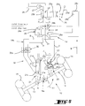
- FIGS 4, 5 and 6 schematically represent the carriage (10) in various positions, as well as the hydraulic means (18a) connected to the circuit hydraulic (18b) which is intended to be supplied by a hydraulic source (25 - 26 - 27) comprising a reservoir (26), a pump (27) and at least one distributor (25).
- a hydraulic source 25 - 26 - 27
- Such a hydraulic source is generally available on the vehicle towing the agricultural machine. However, it could also be planned whether it is part or all of said agricultural machine.
- the agricultural machine according to the invention further comprises at least one control member (19) for controlling the orientation mechanism (18) through the hydraulic circuit (18b).
- This control member (19) allows the wheels (15) to take a position different from the position parallel to the direction of traction (w) of the agricultural machine. It includes in particular a solenoid valve (28). It is by actuating this control member (19), that one allows the axle (13) to take a different orientation from that corresponding displacement in the direction of traction (w) shown diagrammatically in FIG. 4. This orientation will depend on the direction of the oil flow provided by the hydraulic source (25 - 26 - 27), meaning which is defined by the distributor (25).
- the distributor (25) which can be placed in three positions (25a, 25b, 25c), has two inputs (u1, u2) and two outputs (v1, v2).
- the solenoid valve (28) can be placed in two positions (28a, 28b) and includes two inputs (e1, e2) and two outputs (f1, f2).
- This solenoid valve (28) interfaces with the hydraulic circuit (18b), which is consisting of pipes (A, B and C) used to supply the hydraulic cylinders (20, 21), and the hydraulic source (25 - 26 - 27), and more precisely the distributor (25) of it.
- the solenoid valve (28) is linked to the distributor (25) by lines (D, E).
- the distributor (25) and the solenoid valve (28) are respectively controlled by a lever (25d) and a switch (28c).
- the rest position (25a) of the distributor (25) isolates the hydraulic circuit (18b) from the hydraulic source (25 - 26 - 27) and places the pump (27) in communication with the reservoir (26) (inputs (u1, u2) in communication and outputs (v1, v2) closed).
- the lever (25d) makes it possible to select the three positions (25a, 25b, 25c) of the distributor (25) and the switch (28c) allows to choose one of the two positions (28a, 28b) of the solenoid valve (28).
- the latter includes for this purpose an electromagnet (28d) powered by an electrical source (28e) when the switch (28c) is closed.
- a reminder means (29) is provided to return the solenoid valve (28) in its initial position (28a) when the switch (28c) no longer closes the electrical supply circuit of the electromagnet (28d).
- the detailed construction of such a solenoid valve (28) is known per se.
- the distributor (25) is connected, in a known manner, to the hydraulic pump (27) and to the reservoir (26), which are generally, but not limited to, integrated, together with said distributor (25), directly to the vehicle towing the agricultural machine according to the invention.
- the switch (28c) is also advantageously placed in the towing vehicle, while the solenoid valve (28) is installed on the agricultural machine.
- the rod (21a) of the second hydraulic cylinder (21) has, as said more high, one end constituting a piston (21e) so as to separate the cylinder (21b) in two chambers (21f, 21g) of variable volume depending on the position of said piston (21st).
- the first chamber (21f) is connected to the pipe (A) via the orifice (21d) and the second chamber (21g) is connected to the pipe (B) via the orifice (21c).
- Lines (B) and (C), joined from the point of connection (31), as well as line (A) are connected to the solenoid valve (28).
- the position (28a) of the solenoid valve (28), shown in Figure 4, is the rest position in which the switch (28c) is open. In this position, the input (e1) is connected to the outputs (f1) and (f2), and the input (e2) is condemned.
- the solenoid valve (28) communicates with the distributor (25) via the two lines (D) and (E).
- the inputs (e1, e2) of the solenoid valve (28) are respectively in communication with the outputs (v1, v2) of the distributor (25). This the latter is in communication with the hydraulic pump (27) and the reservoir (26) at its inputs (u1, u2).
- the distributor (25) has two parallel paths connecting the inputs (u1, u2) and the outputs (v1, v2) respectively.
- the agricultural machine according to the invention also includes locking means (30) locking in particular the position of the wheels (15) parallel to the direction of traction (w) of the agricultural machine.
- These means of lock (30) are advantageously integrated in the hydraulic circuit (18b).
- the locking means (30) comprise a double piloted valve (30a) mounted on the second hydraulic cylinder (21), preferably directly on the orifices (21c, 21d) of it.
- the piloted double valve (30a) remains open as long that sufficient fluid pressure prevails upstream of said piloted double valve (30a) in each of the pipes (A, B).
- the double piloted valve (30a) allows lock the wheels (15) in a position parallel to the direction of traction (w) in case of one of the pipes (A, B or C).
- the wheels (15) could also be locked in a position parallel to the direction of traction (w) by via another locking device for the wheel support (s) (14) or the (of) wheel (s) (15).
- FIG. 4 shows the agricultural machine according to the invention with the axle (13) oriented orthogonally to the supporting frame (16). This corresponds for example to a displacement in a straight line or in the direction of traction (w) of the carriage (10).
- Such an orientation of the axle (13) is obtained when the distributor (25) is placed in its first active position (25b) called “parallel" (inputs (u1, u2) in communication with the outputs (v1, v2)) and when the switch (28c) is open.
- the switch (28c) is preferably made up a push button so that the opening of the electrical circuit, and by Consequently, the power supply to the electromagnet (28d) is cut off by default.
- the solenoid valve (28) puts the lines (A, B, C) of the hydraulic circuit (18b) in communication with the pump (27) and isolates the tank (26).
- the lines (A, B, C) are then pressurized, which unlocks the piloted double valve (30a) and supplies the chamber (20b) of the first hydraulic cylinder (20) and the chambers (21f, 21g) of the second hydraulic cylinder (21).
- the first hydraulic cylinder (20) extends to the maximum and the rod (20a) abuts against an internal wall of the chamber (20b).
- the second cylinder hydraulic (21) due to the difference in active section existing between its chambers (21f and 21g), then allows to orient the axle (13) appropriately and to put the wheels (15) in a position parallel to the direction of traction (w).
- the piston (21st) has a stroke determined by the position parallel to the direction of traction (w) of the wheels (15) or by the corresponding position of the axle (13).
- the force exerted on the piston (21e) in the first chamber (21f) is greater than that exerted on the piston (21e) on the side of the second chamber (21g), which thus allows keep the given orientation of the axle (13).
- the pressure is exerted on a surface corresponding to a cylinder section complete
- the pressure is exerted on the same area reduced by the area represented by the section of the rod (21a).
- the chamber (20b) of the first hydraulic cylinder (20) has a cylinder section greater than that of the second hydraulic cylinder (21) to maintain the maximum elongation of the first hydraulic cylinder as a priority (20). The force differential applied to the piston (21e) therefore does not allow move the rod (20a) of the first hydraulic cylinder (20).
- the piston (21st) is therefore moves by causing the axle (13) to pivot about the axis (I) to bring the connecting rod (22) (or the end of the first hydraulic cylinder (20)) in support against the mechanical stop (23).
- the latter is, as said before, adjustable to adjust the orientation of the axle (13). This setting is obtained by all known means, for example using a screw (23a).
- Figure 5 shows schematically the orientation mechanism (18) when the distributor (25) is put in its first active position (25b) and when the switch (28c) is closed.
- the solenoid valve (28) is then in its position (28b) and has two parallel tracks connecting the inputs respectively (el, e2) at the outputs (fl, f2).
- Lines (B) and (C) are thus directly connected to the reservoir (26), while the pump (27) supplies the first chamber (21f) of the second hydraulic cylinder (21) after opening the piloted double valve (30a).
- the fluid contained in the second chamber (21g) and in the chamber (20b) flows towards the reservoir (26) and the filling under pressure of the first chamber (21f) allows the axle (13) to pivot around the axis (I) in the direction (N1).
- the amplitude maximum swivel is determined by the maximum shrinkage of the first hydraulic cylinder (20) and its abutment against the mechanical stop (23).
- FIG. 6 shows schematically the orientation mechanism (18) when the distributor (25) is placed in its second active position (25c) called “crossed". In this position, the distributor (25) has two crossed paths connecting the input (u1) on the output (v2) and the input (u2) on the output (v1). The switch (28c) remains closed and the solenoid valve (28) is therefore in the same position (28b) as in FIG. 5.
- Such positioning of the distributor (25) and of the solenoid valve (28) puts the lines (C) in communication with the pump (27), while the line (A) is in communication with the reservoir (26).
- the lines (B, C) are then pressurized, which unlocks double piloted valve (30a) and feeds the second chamber (21g) of the second cylinder hydraulic (21) and the chamber (20b) of the first hydraulic cylinder (20), thus causing the maximum extension of the first hydraulic cylinder (20), the pivoting of the connecting rod (22) and, consequently, the pivoting of the wheels (15) in the direction (N2).
- the maximum amplitude of the pivoting of the axle (13) is determined by the maximum narrowing of the second hydraulic cylinder (21).
- the solenoid valve (28) remains, for fault, in its rest position (28a) (entry (el) in communication with the outputs (f1, f2), input (e2) blocked).
- This position allows, by placing the distributor (25) in its first active position (25b), to supply all the chambers (20b, 21f, 21g) of the hydraulic cylinders (20, 21) via the pipes (A, B, C) so as to orient the wheels (15) parallel to the direction of traction (w).
- the solenoid valve (28) is placed in position (28b) (inputs (el, e2) respectively in communication with the outputs (f1, f2).
- the user can then choose the first active position (25b) or the second active position (25c) of the distributor (25) with the lever (25d), while keeping the switch (28c) closed. He can then orient the axle (13) to take right turns (position (25b)) and left turns (position (25c)), thus facilitating maneuvers at the end of fields, when bypassing obstacles of all kinds or when moving on paths or roads.
- control member (19) is therefore particularly simple to handle and gives the agricultural machine according to the invention a high degree of security.
- the hydraulic circuit (18b) and the hydraulic means (18a) are therefore designed to pressurize all cylinders (20b, 21f, 21g) hydraulic (20, 21) so as to define a position of the axle (13) corresponding to the displacement in the direction of traction (w).
- the straight line of the axle (13) can therefore be obtained so extremely precise, without the slightest drift, even after countless pivotings of said axle (13).
- the agricultural machine according to the invention therefore has appreciable advantages for the user. Improving the maneuverability of said machine allows driving comfort for the user and leads to a significant saving of time during the maneuvers.
- Any type of semi-mounted or trailed agricultural machine can be affected by the present invention. However, it is particularly intended for plows, simple, reversible, fixed width, wide adjustable or variable width.
- the agricultural machine comprises a carriage (10) provided with two wheels (15) mounted on a rigid axle (13) constituting a wheel support (14) common to the two wheels (15).
- each wheel (15) is mounted on its own wheel support (14).
- the wheels (15) may very well not be mounted on a carriage, but directly on the chassis of the agricultural machine via their support wheel.
- the mechanical stop (23) could be secured to the chassis.
- the invention also relates to machines agricultural equipment with a number of wheels other than two: a wheel for example as is for example known in the field of plows.
Landscapes
- Life Sciences & Earth Sciences (AREA)
- Engineering & Computer Science (AREA)
- Mechanical Engineering (AREA)
- Soil Sciences (AREA)
- Environmental Sciences (AREA)
- Vehicle Body Suspensions (AREA)
- Agricultural Machines (AREA)
Applications Claiming Priority (2)
| Application Number | Priority Date | Filing Date | Title |
|---|---|---|---|
| FR9811765 | 1998-09-16 | ||
| FR9811765A FR2783129B1 (fr) | 1998-09-16 | 1998-09-16 | Machine agricole comportant un support de roue directionnel |
Publications (2)
| Publication Number | Publication Date |
|---|---|
| EP0986943A1 true EP0986943A1 (de) | 2000-03-22 |
| EP0986943B1 EP0986943B1 (de) | 2004-02-18 |
Family
ID=9530664
Family Applications (1)
| Application Number | Title | Priority Date | Filing Date |
|---|---|---|---|
| EP19990440245 Expired - Lifetime EP0986943B1 (de) | 1998-09-16 | 1999-09-08 | Landwirtschaftliche Maschine |
Country Status (4)
| Country | Link |
|---|---|
| EP (1) | EP0986943B1 (de) |
| DE (1) | DE69914840T2 (de) |
| DK (1) | DK0986943T3 (de) |
| FR (1) | FR2783129B1 (de) |
Cited By (2)
| Publication number | Priority date | Publication date | Assignee | Title |
|---|---|---|---|---|
| EP4074583A1 (de) | 2021-04-16 | 2022-10-19 | MARMIX GmbH & Co. KG | Hilfsradvorrichtung für zugmaschinen und zugmaschinensystem |
| EP4677974A1 (de) | 2024-07-08 | 2026-01-14 | Lemken GmbH & Co KG | Aufsatteldrehpflug |
Citations (6)
| Publication number | Priority date | Publication date | Assignee | Title |
|---|---|---|---|---|
| FR1567308A (de) * | 1967-04-19 | 1969-05-16 | ||
| FR2376606A1 (fr) | 1977-01-06 | 1978-08-04 | Bonnel Charrues | Mecanisme de direction automatique pour le train de roues arriere d'instruments agricoles reversibles et a retournement hydraulique |
| FR2560478A1 (fr) * | 1984-03-02 | 1985-09-06 | Bonnel Charrues | Dispositif automatique de direction de train de roues arriere pour instruments agricoles a retournement hydraulique |
| FR2658694A1 (fr) * | 1990-02-26 | 1991-08-30 | Bonnel Charrues | Charrue reversible semi-portee sur deux roues. |
| FR2662567A1 (fr) * | 1990-05-29 | 1991-12-06 | Charlier Daniel | Charrue semi-portee a roues orientables. |
| WO1996038032A1 (fr) * | 1995-05-29 | 1996-12-05 | Etablissements Gregoire Besson Et Cie | Charrue multi-socs reversible semi-portee |
-
1998
- 1998-09-16 FR FR9811765A patent/FR2783129B1/fr not_active Expired - Fee Related
-
1999
- 1999-09-08 EP EP19990440245 patent/EP0986943B1/de not_active Expired - Lifetime
- 1999-09-08 DE DE69914840T patent/DE69914840T2/de not_active Expired - Fee Related
- 1999-09-08 DK DK99440245T patent/DK0986943T3/da active
Patent Citations (6)
| Publication number | Priority date | Publication date | Assignee | Title |
|---|---|---|---|---|
| FR1567308A (de) * | 1967-04-19 | 1969-05-16 | ||
| FR2376606A1 (fr) | 1977-01-06 | 1978-08-04 | Bonnel Charrues | Mecanisme de direction automatique pour le train de roues arriere d'instruments agricoles reversibles et a retournement hydraulique |
| FR2560478A1 (fr) * | 1984-03-02 | 1985-09-06 | Bonnel Charrues | Dispositif automatique de direction de train de roues arriere pour instruments agricoles a retournement hydraulique |
| FR2658694A1 (fr) * | 1990-02-26 | 1991-08-30 | Bonnel Charrues | Charrue reversible semi-portee sur deux roues. |
| FR2662567A1 (fr) * | 1990-05-29 | 1991-12-06 | Charlier Daniel | Charrue semi-portee a roues orientables. |
| WO1996038032A1 (fr) * | 1995-05-29 | 1996-12-05 | Etablissements Gregoire Besson Et Cie | Charrue multi-socs reversible semi-portee |
Cited By (2)
| Publication number | Priority date | Publication date | Assignee | Title |
|---|---|---|---|---|
| EP4074583A1 (de) | 2021-04-16 | 2022-10-19 | MARMIX GmbH & Co. KG | Hilfsradvorrichtung für zugmaschinen und zugmaschinensystem |
| EP4677974A1 (de) | 2024-07-08 | 2026-01-14 | Lemken GmbH & Co KG | Aufsatteldrehpflug |
Also Published As
| Publication number | Publication date |
|---|---|
| EP0986943B1 (de) | 2004-02-18 |
| DK0986943T3 (da) | 2004-06-21 |
| FR2783129B1 (fr) | 2000-11-24 |
| DE69914840D1 (de) | 2004-03-25 |
| DE69914840T2 (de) | 2004-12-30 |
| FR2783129A1 (fr) | 2000-03-17 |
Similar Documents
| Publication | Publication Date | Title |
|---|---|---|
| EP3046780B1 (de) | Anordnung mit einem fahrgestell für ein fahrzeug mit variabler spur, z. b. ein landwirtschaftliches fahrzeug wie einen sprüher oder ein hohes reinigungsfahrzeug | |
| FR2501954A1 (fr) | Systeme de controle d'assiette pour outil ou machine et travaillant le sol et circuit de commande destine a ce systeme | |
| FR2636567A1 (fr) | Dispositif pour limiter le pivotement d'un attelage de tracteur agricole | |
| EP0485296B2 (de) | Kupplungssystem zwischen Schlepper und einem Halbanbau-Anhänger | |
| EP4147546B1 (de) | Drehpflug mit verbesserter sicherheit bei konfigurationsänderungen | |
| EP0986943B1 (de) | Landwirtschaftliche Maschine | |
| FR2549793A1 (fr) | Appareil de direction assistee pour tracteur | |
| EP0653343B1 (de) | Steuereinrichtung zum Lenken der Hinterräder eines Anhängers | |
| EP3698612A1 (de) | Pflug mit kompensationsvorrichtung der seitlichen belastung beim arbeiten | |
| EP0612464A1 (de) | Sämaschine | |
| FR2517506A1 (fr) | Charrue portee reversible equipee d'un mecanisme de pivotement | |
| EP2959759B1 (de) | Landwirtschaftliche maschine, die mit einer zentriervorrichtung ausgestattet ist | |
| FR2859440A1 (fr) | Essieu directeur a recuperation de trajectoire | |
| EP0857014A1 (de) | Breitenveränderlicher, getragener umkehrpflug mit umkehrachsengestellzentrierungsvorrichtung | |
| EP3973754B1 (de) | Drehpflug vom typ aufsattelpflug mit wagen oder einzelrad | |
| FR2758228A1 (fr) | Machine agricole, en particulier de preparation du sol et de dechaumage comportant des moyens d'entrainement en pivotement des trains porteurs d'outils | |
| EP0237422B1 (de) | Hydraulik-Systeme für einen Aufsatteldrehpflug mit verschwenkbarem Stützrad | |
| FR2551015A1 (fr) | Vehicule a train avant et chassis deportables lateralement relativement | |
| FR2627931A1 (fr) | Charrue a largeur de travail variable | |
| FR2590759A1 (fr) | Perfectionnements aux charrues reversibles | |
| FR2912867A1 (fr) | Machine de travail du sol comportant, a l'arriere, des outils de type rouleaux dont le relevage peut etre commande de facon a regler la profondeur de travail | |
| FR2699041A1 (fr) | Machine agricole de travail du sol avec un dispositif de retournement perfectionné. | |
| FR2658694A1 (fr) | Charrue reversible semi-portee sur deux roues. | |
| EP0603044A1 (de) | Drehpflug mit einem quer zu der Arbeitsebene schwenkbaren Rahmen | |
| WO1996038032A1 (fr) | Charrue multi-socs reversible semi-portee |
Legal Events
| Date | Code | Title | Description |
|---|---|---|---|
| PUAI | Public reference made under article 153(3) epc to a published international application that has entered the european phase |
Free format text: ORIGINAL CODE: 0009012 |
|
| AK | Designated contracting states |
Kind code of ref document: A1 Designated state(s): DE DK FR |
|
| AX | Request for extension of the european patent |
Free format text: AL;LT;LV;MK;RO;SI |
|
| 17P | Request for examination filed |
Effective date: 20000911 |
|
| AKX | Designation fees paid |
Free format text: DE DK FR |
|
| 17Q | First examination report despatched |
Effective date: 20020729 |
|
| GRAP | Despatch of communication of intention to grant a patent |
Free format text: ORIGINAL CODE: EPIDOSNIGR1 |
|
| GRAS | Grant fee paid |
Free format text: ORIGINAL CODE: EPIDOSNIGR3 |
|
| GRAA | (expected) grant |
Free format text: ORIGINAL CODE: 0009210 |
|
| AK | Designated contracting states |
Kind code of ref document: B1 Designated state(s): DE DK FR |
|
| REF | Corresponds to: |
Ref document number: 69914840 Country of ref document: DE Date of ref document: 20040325 Kind code of ref document: P |
|
| REG | Reference to a national code |
Ref country code: DK Ref legal event code: T3 |
|
| PLBE | No opposition filed within time limit |
Free format text: ORIGINAL CODE: 0009261 |
|
| STAA | Information on the status of an ep patent application or granted ep patent |
Free format text: STATUS: NO OPPOSITION FILED WITHIN TIME LIMIT |
|
| 26N | No opposition filed |
Effective date: 20041119 |
|
| PGFP | Annual fee paid to national office [announced via postgrant information from national office to epo] |
Ref country code: DK Payment date: 20080826 Year of fee payment: 10 |
|
| PGFP | Annual fee paid to national office [announced via postgrant information from national office to epo] |
Ref country code: DE Payment date: 20081002 Year of fee payment: 10 |
|
| PGFP | Annual fee paid to national office [announced via postgrant information from national office to epo] |
Ref country code: FR Payment date: 20080929 Year of fee payment: 10 |
|
| REG | Reference to a national code |
Ref country code: DK Ref legal event code: EBP |
|
| REG | Reference to a national code |
Ref country code: FR Ref legal event code: ST Effective date: 20100531 |
|
| PG25 | Lapsed in a contracting state [announced via postgrant information from national office to epo] |
Ref country code: FR Free format text: LAPSE BECAUSE OF NON-PAYMENT OF DUE FEES Effective date: 20090930 Ref country code: DE Free format text: LAPSE BECAUSE OF NON-PAYMENT OF DUE FEES Effective date: 20100401 |
|
| PG25 | Lapsed in a contracting state [announced via postgrant information from national office to epo] |
Ref country code: DK Free format text: LAPSE BECAUSE OF NON-PAYMENT OF DUE FEES Effective date: 20090930 |