EP0986995B1 - Umfüllvorrichtung für Knochenzement - Google Patents
Umfüllvorrichtung für Knochenzement Download PDFInfo
- Publication number
- EP0986995B1 EP0986995B1 EP99810741A EP99810741A EP0986995B1 EP 0986995 B1 EP0986995 B1 EP 0986995B1 EP 99810741 A EP99810741 A EP 99810741A EP 99810741 A EP99810741 A EP 99810741A EP 0986995 B1 EP0986995 B1 EP 0986995B1
- Authority
- EP
- European Patent Office
- Prior art keywords
- piston
- transfer filling
- sleeve
- accordance
- filling apparatus
- Prior art date
- Legal status (The legal status is an assumption and is not a legal conclusion. Google has not performed a legal analysis and makes no representation as to the accuracy of the status listed.)
- Expired - Lifetime
Links
- 239000002639 bone cement Substances 0.000 title claims abstract description 36
- 239000004568 cement Substances 0.000 claims abstract description 31
- 238000003825 pressing Methods 0.000 claims abstract description 4
- 239000000470 constituent Substances 0.000 claims 1
- 239000011888 foil Substances 0.000 claims 1
- 239000007921 spray Substances 0.000 abstract 3
- 230000008901 benefit Effects 0.000 description 6
- 239000007788 liquid Substances 0.000 description 6
- 238000007789 sealing Methods 0.000 description 4
- 230000003068 static effect Effects 0.000 description 3
- 230000007704 transition Effects 0.000 description 3
- 238000000926 separation method Methods 0.000 description 2
- 101100327917 Caenorhabditis elegans chup-1 gene Proteins 0.000 description 1
- 241000209035 Ilex Species 0.000 description 1
- 239000000853 adhesive Substances 0.000 description 1
- 230000001070 adhesive effect Effects 0.000 description 1
- 239000011324 bead Substances 0.000 description 1
- 230000008859 change Effects 0.000 description 1
- 230000001419 dependent effect Effects 0.000 description 1
- 230000000881 depressing effect Effects 0.000 description 1
- 230000009969 flowable effect Effects 0.000 description 1
- 230000005484 gravity Effects 0.000 description 1
- 238000001746 injection moulding Methods 0.000 description 1
- 238000004519 manufacturing process Methods 0.000 description 1
- 239000000203 mixture Substances 0.000 description 1
- 239000000843 powder Substances 0.000 description 1
- 230000035484 reaction time Effects 0.000 description 1
- 230000009467 reduction Effects 0.000 description 1
- 238000003756 stirring Methods 0.000 description 1
- 239000000725 suspension Substances 0.000 description 1
- 229920001169 thermoplastic Polymers 0.000 description 1
- 239000004416 thermosoftening plastic Substances 0.000 description 1
Images



Classifications
-
- B—PERFORMING OPERATIONS; TRANSPORTING
- B05—SPRAYING OR ATOMISING IN GENERAL; APPLYING FLUENT MATERIALS TO SURFACES, IN GENERAL
- B05C—APPARATUS FOR APPLYING FLUENT MATERIALS TO SURFACES, IN GENERAL
- B05C17/00—Hand tools or apparatus using hand held tools, for applying liquids or other fluent materials to, for spreading applied liquids or other fluent materials on, or for partially removing applied liquids or other fluent materials from, surfaces
- B05C17/005—Hand tools or apparatus using hand held tools, for applying liquids or other fluent materials to, for spreading applied liquids or other fluent materials on, or for partially removing applied liquids or other fluent materials from, surfaces for discharging material from a reservoir or container located in or on the hand tool through an outlet orifice by pressure without using surface contacting members like pads or brushes
- B05C17/01—Hand tools or apparatus using hand held tools, for applying liquids or other fluent materials to, for spreading applied liquids or other fluent materials on, or for partially removing applied liquids or other fluent materials from, surfaces for discharging material from a reservoir or container located in or on the hand tool through an outlet orifice by pressure without using surface contacting members like pads or brushes with manually mechanically or electrically actuated piston or the like
-
- A—HUMAN NECESSITIES
- A61—MEDICAL OR VETERINARY SCIENCE; HYGIENE
- A61B—DIAGNOSIS; SURGERY; IDENTIFICATION
- A61B17/00—Surgical instruments, devices or methods
- A61B17/56—Surgical instruments or methods for treatment of bones or joints; Devices specially adapted therefor
- A61B17/58—Surgical instruments or methods for treatment of bones or joints; Devices specially adapted therefor for osteosynthesis, e.g. bone plates, screws or setting implements
- A61B17/88—Osteosynthesis instruments; Methods or means for implanting or extracting internal or external fixation devices
- A61B17/8802—Equipment for handling bone cement or other fluid fillers
- A61B17/8805—Equipment for handling bone cement or other fluid fillers for introducing fluid filler into bone or extracting it
- A61B17/8825—Equipment for handling bone cement or other fluid fillers for introducing fluid filler into bone or extracting it characterised by syringe details
-
- A—HUMAN NECESSITIES
- A61—MEDICAL OR VETERINARY SCIENCE; HYGIENE
- A61B—DIAGNOSIS; SURGERY; IDENTIFICATION
- A61B17/00—Surgical instruments, devices or methods
- A61B17/56—Surgical instruments or methods for treatment of bones or joints; Devices specially adapted therefor
- A61B17/58—Surgical instruments or methods for treatment of bones or joints; Devices specially adapted therefor for osteosynthesis, e.g. bone plates, screws or setting implements
- A61B17/88—Osteosynthesis instruments; Methods or means for implanting or extracting internal or external fixation devices
- A61B17/8802—Equipment for handling bone cement or other fluid fillers
- A61B17/8833—Osteosynthesis tools specially adapted for handling bone cement or fluid fillers; Means for supplying bone cement or fluid fillers to introducing tools, e.g. cartridge handling means
-
- A—HUMAN NECESSITIES
- A61—MEDICAL OR VETERINARY SCIENCE; HYGIENE
- A61B—DIAGNOSIS; SURGERY; IDENTIFICATION
- A61B17/00—Surgical instruments, devices or methods
- A61B17/56—Surgical instruments or methods for treatment of bones or joints; Devices specially adapted therefor
- A61B17/58—Surgical instruments or methods for treatment of bones or joints; Devices specially adapted therefor for osteosynthesis, e.g. bone plates, screws or setting implements
- A61B17/88—Osteosynthesis instruments; Methods or means for implanting or extracting internal or external fixation devices
- A61B17/8802—Equipment for handling bone cement or other fluid fillers
- A61B17/8833—Osteosynthesis tools specially adapted for handling bone cement or fluid fillers; Means for supplying bone cement or fluid fillers to introducing tools, e.g. cartridge handling means
- A61B2017/8838—Osteosynthesis tools specially adapted for handling bone cement or fluid fillers; Means for supplying bone cement or fluid fillers to introducing tools, e.g. cartridge handling means for mixing bone cement or fluid fillers
-
- A—HUMAN NECESSITIES
- A61—MEDICAL OR VETERINARY SCIENCE; HYGIENE
- A61B—DIAGNOSIS; SURGERY; IDENTIFICATION
- A61B50/00—Containers, covers, furniture or holders specially adapted for surgical or diagnostic appliances or instruments, e.g. sterile covers
- A61B2050/005—Containers, covers, furniture or holders specially adapted for surgical or diagnostic appliances or instruments, e.g. sterile covers with a lid or cover
- A61B2050/0062—Containers, covers, furniture or holders specially adapted for surgical or diagnostic appliances or instruments, e.g. sterile covers with a lid or cover closable by a combination of rotation and translation
- A61B2050/0063—Bayonet coupling
-
- A—HUMAN NECESSITIES
- A61—MEDICAL OR VETERINARY SCIENCE; HYGIENE
- A61B—DIAGNOSIS; SURGERY; IDENTIFICATION
- A61B50/00—Containers, covers, furniture or holders specially adapted for surgical or diagnostic appliances or instruments, e.g. sterile covers
- A61B2050/005—Containers, covers, furniture or holders specially adapted for surgical or diagnostic appliances or instruments, e.g. sterile covers with a lid or cover
- A61B2050/0067—Types of closures or fasteners
- A61B2050/0083—Snap connection
-
- A—HUMAN NECESSITIES
- A61—MEDICAL OR VETERINARY SCIENCE; HYGIENE
- A61F—FILTERS IMPLANTABLE INTO BLOOD VESSELS; PROSTHESES; DEVICES PROVIDING PATENCY TO, OR PREVENTING COLLAPSING OF, TUBULAR STRUCTURES OF THE BODY, e.g. STENTS; ORTHOPAEDIC, NURSING OR CONTRACEPTIVE DEVICES; FOMENTATION; TREATMENT OR PROTECTION OF EYES OR EARS; BANDAGES, DRESSINGS OR ABSORBENT PADS; FIRST-AID KITS
- A61F2/00—Filters implantable into blood vessels; Prostheses, i.e. artificial substitutes or replacements for parts of the body; Appliances for connecting them with the body; Devices providing patency to, or preventing collapsing of, tubular structures of the body, e.g. stents
- A61F2/02—Prostheses implantable into the body
- A61F2/30—Joints
- A61F2/46—Special tools for implanting artificial joints
- A61F2/4603—Special tools for implanting artificial joints for insertion or extraction of endoprosthetic joints or of accessories thereof
-
- A—HUMAN NECESSITIES
- A61—MEDICAL OR VETERINARY SCIENCE; HYGIENE
- A61F—FILTERS IMPLANTABLE INTO BLOOD VESSELS; PROSTHESES; DEVICES PROVIDING PATENCY TO, OR PREVENTING COLLAPSING OF, TUBULAR STRUCTURES OF THE BODY, e.g. STENTS; ORTHOPAEDIC, NURSING OR CONTRACEPTIVE DEVICES; FOMENTATION; TREATMENT OR PROTECTION OF EYES OR EARS; BANDAGES, DRESSINGS OR ABSORBENT PADS; FIRST-AID KITS
- A61F2/00—Filters implantable into blood vessels; Prostheses, i.e. artificial substitutes or replacements for parts of the body; Appliances for connecting them with the body; Devices providing patency to, or preventing collapsing of, tubular structures of the body, e.g. stents
- A61F2/02—Prostheses implantable into the body
- A61F2/30—Joints
- A61F2002/30001—Additional features of subject-matter classified in A61F2/28, A61F2/30 and subgroups thereof
- A61F2002/30003—Material related properties of the prosthesis or of a coating on the prosthesis
- A61F2002/3006—Properties of materials and coating materials
- A61F2002/30065—Properties of materials and coating materials thermoplastic, i.e. softening or fusing when heated, and hardening and becoming rigid again when cooled
-
- A—HUMAN NECESSITIES
- A61—MEDICAL OR VETERINARY SCIENCE; HYGIENE
- A61F—FILTERS IMPLANTABLE INTO BLOOD VESSELS; PROSTHESES; DEVICES PROVIDING PATENCY TO, OR PREVENTING COLLAPSING OF, TUBULAR STRUCTURES OF THE BODY, e.g. STENTS; ORTHOPAEDIC, NURSING OR CONTRACEPTIVE DEVICES; FOMENTATION; TREATMENT OR PROTECTION OF EYES OR EARS; BANDAGES, DRESSINGS OR ABSORBENT PADS; FIRST-AID KITS
- A61F2/00—Filters implantable into blood vessels; Prostheses, i.e. artificial substitutes or replacements for parts of the body; Appliances for connecting them with the body; Devices providing patency to, or preventing collapsing of, tubular structures of the body, e.g. stents
- A61F2/02—Prostheses implantable into the body
- A61F2/30—Joints
- A61F2002/30001—Additional features of subject-matter classified in A61F2/28, A61F2/30 and subgroups thereof
- A61F2002/30667—Features concerning an interaction with the environment or a particular use of the prosthesis
- A61F2002/30716—Features concerning an interaction with the environment or a particular use of the prosthesis for single use, e.g. having means for preventing re-use
-
- A—HUMAN NECESSITIES
- A61—MEDICAL OR VETERINARY SCIENCE; HYGIENE
- A61F—FILTERS IMPLANTABLE INTO BLOOD VESSELS; PROSTHESES; DEVICES PROVIDING PATENCY TO, OR PREVENTING COLLAPSING OF, TUBULAR STRUCTURES OF THE BODY, e.g. STENTS; ORTHOPAEDIC, NURSING OR CONTRACEPTIVE DEVICES; FOMENTATION; TREATMENT OR PROTECTION OF EYES OR EARS; BANDAGES, DRESSINGS OR ABSORBENT PADS; FIRST-AID KITS
- A61F2210/00—Particular material properties of prostheses classified in groups A61F2/00 - A61F2/26 or A61F2/82 or A61F9/00 or A61F11/00 or subgroups thereof
- A61F2210/0071—Particular material properties of prostheses classified in groups A61F2/00 - A61F2/26 or A61F2/82 or A61F9/00 or A61F11/00 or subgroups thereof thermoplastic
-
- A—HUMAN NECESSITIES
- A61—MEDICAL OR VETERINARY SCIENCE; HYGIENE
- A61F—FILTERS IMPLANTABLE INTO BLOOD VESSELS; PROSTHESES; DEVICES PROVIDING PATENCY TO, OR PREVENTING COLLAPSING OF, TUBULAR STRUCTURES OF THE BODY, e.g. STENTS; ORTHOPAEDIC, NURSING OR CONTRACEPTIVE DEVICES; FOMENTATION; TREATMENT OR PROTECTION OF EYES OR EARS; BANDAGES, DRESSINGS OR ABSORBENT PADS; FIRST-AID KITS
- A61F2250/00—Special features of prostheses classified in groups A61F2/00 - A61F2/26 or A61F2/82 or A61F9/00 or A61F11/00 or subgroups thereof
- A61F2250/0058—Additional features; Implant or prostheses properties not otherwise provided for
- A61F2250/009—Additional features; Implant or prostheses properties not otherwise provided for for single use, e.g. having means for preventing re-use
-
- B—PERFORMING OPERATIONS; TRANSPORTING
- B01—PHYSICAL OR CHEMICAL PROCESSES OR APPARATUS IN GENERAL
- B01F—MIXING, e.g. DISSOLVING, EMULSIFYING OR DISPERSING
- B01F2101/00—Mixing characterised by the nature of the mixed materials or by the application field
- B01F2101/20—Mixing of ingredients for bone cement
Definitions
- the invention relates to a transfer device for bone cement a cylindrical mixing container open at the top and one inside insertable filling plunger, removable with the sleeve of a cement syringe is connected and has an opening through which the mixed Bone cement by pressing the decanting piston into the sleeve is refillable.
- the object of the invention is to improve this situation.
- This task is solved with the characteristics of independent claim 1, that an ejection piston is inserted in the sleeve, which in the area of Opening for the flowing cement has a breakthrough, which after removing the cement syringe with a stopper is lockable.
- This has the advantage that the real one large dynamic distribution and dimensioned for pressing Seal is already installed when the bone cement is in the syringe arrives and that the smaller remaining breakthrough is only static must be sealed.
- the cross section of the breakthrough so adaptable to the viscosity of a preferred bone cement, that backflow is largely prevented. Further improvements result from the dependent claims 2 to 12.
- a slight prepress between the nozzle and Ejection piston can be reached if the ejection piston is in a lower position in the sleeve can be fixed, for example by a force and positive snap connection.
- a grip part has the advantage that relatively large forces act on the transfer piston for transferring the bone cement are transferable without this there is a load on the connection between the sleeve and the transfer piston.
- the cross-section of the opening and nozzle can be chosen to be smaller when large forces are transferred to the transfer piston can.
- the mixing container can be used as a transport container for one of the components should be made of bone cement so that a anyway designed as a disposable part fulfills a multiple function.
- a Powdery component of the bone cement can be used for transportation a lid or a tear-off film can be enclosed in the mixing container. After removing the cover or tear-off film, more can Components are added and mixed by hand with a spatula become. The transfer flask is then placed on which the The syringe barrel and the ejection plunger are supplied pre-assembled were. After mixing, the operator only has to Insert the transfer piston and press it down, the sleeve from the transfer piston loosen and put on the squeeze gun and this without adhesive Apply bone cement residues to the surfaces that are accessible from the outside.
- a decanting device for bone cement with a cylindrical, upwardly open mixing container 1 and with one therein insertable transfer piston 2, which is removable with the sleeve 4 one Cement syringe 3 is connected and has an opening 5 through which the mixed bone cement 6 by depressing the transfer piston 2 in the Sleeve 4 is transferable.
- There is an ejection piston 7 in the sleeve 4 used in the area of the opening 5 for the flowing cement has an opening 8, which after removing the Cement syringe 3 can be closed with a stopper.
- the actual piston with piston surface 26 is thin-walled executed and provided with a handle part 13 which consists of a tube piece exists, which is much higher than the mixing container 1 and in one laterally projecting ring 22 ends, on which the transfer piston from Hand can be pressed down to the bottom of the mixing container 1.
- Parallel to the longitudinal axis 28 are longitudinal ribs 23 on the pipe section Distributed circumference, the guides an inclined position of the piston surface 26th and prevent their sealing edge in the mixing container.
- In the lower part of the Pipe piece are attached to two windows 24 offset by 180 ° to a further inner ring 27 on laterally demoldable Tool stamps each have a pin 25 for a bayonet lock eject.
- the mixing container 1 is shown as a transport container, which with a Cover 21 is closed via a snap connection 30 to store powdery portions 17 of the bone cement and to transport.
- the cover 21 is torn open laterally and removed. Then one Liquid component from a separate container of powder component 17 added and all during a given reaction time stir and mix as evenly as possible. The so created and for a limited time flowable bone cement 6 must now in a Cement syringe 3 are transferred.
- Fig. 3 the actual cement syringe 3 is shown, which is a cylindrical Has sleeve 4 with a conical transition 18 and a distribution pipe 19.
- the lower edge of the sleeve 4 is reinforced on the outside and has four Cutouts for a bayonet lock 15.
- a lower position 16 is by means of a small change (not shown) in the inner diameter the sleeve 4 fixed an ejection piston 7, the piston surface of the inclination is adapted from the conical transition 18.
- the discharge piston 7 has in Center an opening 8, the outer dimensions of a nozzle 12th (Fig. 4) is adapted. Obtained by a support ring 31 and radial ribs 32 the ejection piston 7 has high rigidity against high ejection pressures.
- the pressing-out piston 7 is fixed in the lower position 16 in this way dimensioned so that it only moves upwards with a greater axial force can move.
- Fig. 4 the elements are visible, which on the sleeve 4 and on the Ejection piston 7 of the cement syringe 3 are adapted.
- One on the piston crown molded guide ring 27 corresponds to that with its outer diameter Inner diameter of the sleeve 4 and has two pins 25 which together with the recesses at the lower end of the sleeve 4 one Form bayonet lock 15, which the axial position between the sleeve 4 and Decanting piston 2 defines.
- the locked unit of decanting piston 2 and cement syringe 3 is on Gripped part 13 and from above in a mixing cup 1 with fresh Bone cement 6 inserted.
- This When hitting the bone cement 6, this must be displaced through the mouth 12 into the cement syringe 3 become.
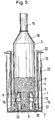
- Axial force are applied to the ring 22 until the transfer piston 2, as in Fig. 5 shown, has reached the bottom of the mixing container 1. 5 the nozzle 12 penetrates the squeezing piston 7 completely, so that the Bone cement 6 flowing into the sleeve 4 under gravity evenly distributed in the sleeve 4 and fills it slowly, the excess air is displaced through the distribution pipe 19.
- Bone cement 6 When the bottom is reached, except for a residual amount in the nozzle 12 Bone cement 6 has been completely poured into the cement syringe 3 and extends into the distribution pipe 19. With a very thin liquid After decanting, bone cement 6 can have a (not shown here) Cap to be attached to the manifold 19 to a Refill of bone cement when separating the Bayonet lock 15 between decanting piston 2 and cement syringe 3 prevent. Below the ejection piston 7 there is a cavity 33 which is so well ventilated that when loosening the bayonet lock 15 and when Pull off the cement syringe 3 at the point of separation between the breakthrough 8 and the shoulder 29 air for constriction and separation of the Bone cement 6 can flow in the breakthrough 8. To solve the Bayonet lock 15, the sleeve 3 in its upper region with a Hand grasped while with the other hand a corresponding one Counterforce is applied to the handle part 13, 22.
- FIG Squeeze gun 11 The removed cement syringe 3 is placed on a as shown in FIG Squeeze gun 11 attached.
- the latter has an extendable Piston rod 10, on which a stopper 9 has been fitted, in order to Plug 9 to seal the opening 8 and ejection forces on the To transfer ejection piston 7.
- the piston rod 10 experiences through a Trigger lever 35, which is moved against a pistol grip 34, a Feed movement that is strongly reduced to a large ejection force produce.
- To transfer a greater output force grab everyone four recesses of the sleeve 4 pins to the bayonet lock 15 too form.
- the high ejection force is necessary in order to Cross-sectional reduction on the diameter of the distribution pipe 19 and To overcome friction on the distribution pipe 19 and sleeve 4.
- the pens are in supported a connector 36 which, like the guide ring 27 in Transfer piston 2 is adapted to the inner diameter of the sleeve 4 the latter an alignment in the direction of the feed movement of the To give piston
Landscapes
- Health & Medical Sciences (AREA)
- Orthopedic Medicine & Surgery (AREA)
- Surgery (AREA)
- Life Sciences & Earth Sciences (AREA)
- Engineering & Computer Science (AREA)
- Animal Behavior & Ethology (AREA)
- Public Health (AREA)
- Heart & Thoracic Surgery (AREA)
- Medical Informatics (AREA)
- Molecular Biology (AREA)
- Nuclear Medicine, Radiotherapy & Molecular Imaging (AREA)
- General Health & Medical Sciences (AREA)
- Biomedical Technology (AREA)
- Veterinary Medicine (AREA)
- Mechanical Engineering (AREA)
- Prostheses (AREA)
- Surgical Instruments (AREA)
- Mixers With Rotating Receptacles And Mixers With Vibration Mechanisms (AREA)
- Pharmaceuticals Containing Other Organic And Inorganic Compounds (AREA)
- Medicinal Preparation (AREA)
Description
- Fig. 1
- Schematisch eine Ansicht eines Umfüllkolbens mit einem Griffteil, welches Längsrippen zur Führung des eigentlichen Kolbens aufweist;
- Fig. 2
- schematisch einen Längsschnitt durch einen Mischbehälter der vorgängig als Transportbehälter und nach dem Mischen als Zylinder für einen Umfüllkolben nach Fig. 1 verwendbar ist;
- Fig. 3
- schematisch einen Längsschnitt durch eine Zementspritze, in deren Hülse ein Ausstosskolben mit einem mittleren Durchbruch vormontiert ist;
- Fig. 4
- schematisch einen Längsschnitt durch einen Umfüllkolben von Fig. 1, in welchen mit einem Bajonettverschluss eine Anordnung gemäss Fig. 3 einsetzbar ist;
- Fig. 5
- schematisch im Längsschnitt einen Umfüllkolben mit Zementspritze in seiner untersten Stellung im Mischbehälter; und
- Fig. 6
- schematisch im Längsschnitt die Zementspritze von Fig. 5 nach dem Aufsetzen auf eine Auspresspistole.
Claims (13)
- Umfüllvorrichtung für Knochenzement mit einem zylindrischen, nach oben offenen Mischbehälter (1) und einem darin einsetzbaren Umfüllkolben (2), der abnehmbar mit der Hülse (4) einer Zementspritze (3) verbunden ist und eine Öffnung (5) aufweist, durch welche der gemischte Knochenzement (6) durch Niederdrücken des Umfüllkolbens (2) in die Hülse (4) umfüllbar ist, dadurch gekennzeichnet, dass in der Hülse (4) ein Ausstosskolben (7) eingesetzt ist, der im Bereich der Öffnung (5) für den durchfliessenden Zement einen Durchbruch (8) aufweist, welcher nach dem Abnehmen der Zementspritze (3) mit einem Stopfen (9) verschliessbar ist.
- Umfüllvorrichtung nach Anspruch 1, dadurch gekennzeichnet, dass die kleinste Durchtrittsfläche im Durchbruch (8) weniger als 50 Prozent der inneren Querschnittsfläche der Hülse (4) entspricht.
- Umfüllvorrichtung nach Anspruch 2, dadurch gekennzeichnet, dass die kleinste Durchtrittsfläche im Durchbruch (8) zwischen 25 und 5 Prozent der inneren Querschnittsfläche der Hülse (4) entspricht.
- Umfüllvorrichtung nach Anspruch 1 bis 3, dadurch gekennzeichnet, dass der Stopfen (9) durch ein Ende einer Kolbenstange (10) gebildet ist als Bestandteil einer Auspresspistole (11), welche lösbar mit der Hülse (4) verbindbar ist.
- Umfüllvorrichtung nach Anspruch 1 bis 4, dadurch gekennzeichnet, dass die Öffnung (5) als eine Düse (12) ausgeformt ist, die in den Durchbruch (8) des Ausstosskolbens (7) hineinragt.
- Umfüllvorrichtung nach einem der Ansprüche 1 bis 5, dadurch gekennzeichnet, dass der Ausstosskolben (7) in einer unteren Position (16) in der Hülse (4) fixierbar ist.
- Umfüllvorrichtung nach Anspruch 1 bis 6, dadurch gekennzeichnet, dass Hülse (4) und Umfüllkolben (2) durch einen Drehverschluss (14) beispielsweise durch einen Bajonettverschluss (15) verbindbar sind.
- Umfüllvorrichtung nach Anspruch 1 bis 7, dadurch gekennzeichnet, dass der Umfüllkolben (2) einen Griffteil (13) aufweist, welcher ein Bewegen des Umfüllkolbens (2) von Hand ermöglicht.
- Umfüllvorrichtung nach Anspruch 4 bis 8, dadurch gekennzeichnet, dass die Hülse (4) mit der gleichen Art von Verschluss sowohl mit dem Ausstosskolben (7) als auch mit der Auspresspistole (11) verbindbar ist.
- Umfüllvorrichtung nach Anspruch 7, dadurch gekennzeichnet, dass der Umfüllkolben (2) mindestens in seiner untersten Position im Mischbehälter (1) gegen Drehen blockiert ist.
- Umfüllvorrichtung nach Anspruch 1 bis 10, dadurch gekennzeichnet, dass der Mischbehälter (1) als verschliessbarer Transportbehälter für mindestens eine der Komponenten (17) eines zu mischenden Knochenzementes (6) ausgeführt ist.
- Umfüllvorrichtung nach Anspruch 11, dadurch gekennzeichnet, dass der Mischbehälter (1) für den Transport von Komponenten von Knochenzement mit einem Deckel (21) oder mit einer Folie verschliessbar ist.
- Umfüllvorrichtung nach Anspruch 8, dadurch gekennzeichnet, dass der Griffteil (13) mit Längsrippen (23) versehen ist, die in Längsrichtung am Mischbehälter (1) anliegen, um dem Umfüllkolben (2) eine Führung zu geben.
Priority Applications (1)
| Application Number | Priority Date | Filing Date | Title |
|---|---|---|---|
| EP99810741A EP0986995B1 (de) | 1998-09-16 | 1999-08-18 | Umfüllvorrichtung für Knochenzement |
Applications Claiming Priority (3)
| Application Number | Priority Date | Filing Date | Title |
|---|---|---|---|
| EP98810925 | 1998-09-16 | ||
| EP98810925 | 1998-09-16 | ||
| EP99810741A EP0986995B1 (de) | 1998-09-16 | 1999-08-18 | Umfüllvorrichtung für Knochenzement |
Publications (2)
| Publication Number | Publication Date |
|---|---|
| EP0986995A1 EP0986995A1 (de) | 2000-03-22 |
| EP0986995B1 true EP0986995B1 (de) | 2003-10-01 |
Family
ID=8236327
Family Applications (1)
| Application Number | Title | Priority Date | Filing Date |
|---|---|---|---|
| EP99810741A Expired - Lifetime EP0986995B1 (de) | 1998-09-16 | 1999-08-18 | Umfüllvorrichtung für Knochenzement |
Country Status (6)
| Country | Link |
|---|---|
| US (2) | US6238399B1 (de) |
| EP (1) | EP0986995B1 (de) |
| JP (1) | JP2000126214A (de) |
| AT (1) | ATE250907T1 (de) |
| DE (1) | DE59907170D1 (de) |
| ES (1) | ES2209370T3 (de) |
Families Citing this family (29)
| Publication number | Priority date | Publication date | Assignee | Title |
|---|---|---|---|---|
| US6502608B1 (en) * | 2000-02-14 | 2003-01-07 | Telios Orthopedic Systems, Inc. | Delivery apparatus, nozzle, and removable tip assembly |
| US7175336B2 (en) * | 2001-01-26 | 2007-02-13 | Depuy Acromed, Inc. | Graft delivery system |
| US7008433B2 (en) * | 2001-02-15 | 2006-03-07 | Depuy Acromed, Inc. | Vertebroplasty injection device |
| DE10258140B4 (de) * | 2002-12-04 | 2005-12-22 | Aesculap Ag & Co. Kg | System zum Befüllen von Applikationsbehältern |
| US20040122438A1 (en) * | 2002-12-23 | 2004-06-24 | Boston Scientific Corporation | Flex-tight interlocking connection tubing for delivery of bone cements/biomaterials for vertebroplasty |
| ES2545328T3 (es) | 2003-03-14 | 2015-09-10 | Depuy Spine, Inc. | Dispositivo hidráulico de inyección de cemento óseo en vertebroplastia percutánea |
| US8066713B2 (en) | 2003-03-31 | 2011-11-29 | Depuy Spine, Inc. | Remotely-activated vertebroplasty injection device |
| US7112205B2 (en) * | 2003-06-17 | 2006-09-26 | Boston Scientific Scimed, Inc. | Apparatus and methods for delivering compounds into vertebrae for vertebroplasty |
| US8415407B2 (en) | 2004-03-21 | 2013-04-09 | Depuy Spine, Inc. | Methods, materials, and apparatus for treating bone and other tissue |
| WO2006011152A2 (en) | 2004-06-17 | 2006-02-02 | Disc-O-Tech Medical Technologies, Ltd. | Methods for treating bone and other tissue |
| WO2005030034A2 (en) | 2003-09-26 | 2005-04-07 | Depuy Spine, Inc. | Device for delivering viscous material |
| US7524103B2 (en) * | 2003-11-18 | 2009-04-28 | Boston Scientific Scimed, Inc. | Apparatus for mixing and dispensing a multi-component bone cement |
| US7841114B2 (en) * | 2004-07-26 | 2010-11-30 | Avery Dennison Corporation | Angled top view printable hanging file tabs |
| US20080319445A9 (en) * | 2004-08-17 | 2008-12-25 | Scimed Life Systems, Inc. | Apparatus and methods for delivering compounds into vertebrae for vertebroplasty |
| US8038682B2 (en) * | 2004-08-17 | 2011-10-18 | Boston Scientific Scimed, Inc. | Apparatus and methods for delivering compounds into vertebrae for vertebroplasty |
| CA2603033A1 (en) * | 2005-04-29 | 2006-11-09 | Wyeth | Drug delivery devices and related components, systems and methods |
| US9381024B2 (en) | 2005-07-31 | 2016-07-05 | DePuy Synthes Products, Inc. | Marked tools |
| US9918767B2 (en) | 2005-08-01 | 2018-03-20 | DePuy Synthes Products, Inc. | Temperature control system |
| US8360629B2 (en) | 2005-11-22 | 2013-01-29 | Depuy Spine, Inc. | Mixing apparatus having central and planetary mixing elements |
| US20080027443A1 (en) * | 2006-07-26 | 2008-01-31 | Lambert Systms, L.L.C. | Biocompatible Anchoring Device For A Soft Tissue Graft, Method Of Making And Method Of Using |
| US20080039855A1 (en) * | 2006-07-26 | 2008-02-14 | Lambert Systems, L.L.C. | Device For Delivering Bone Cement Precursors, Composites Thereof, Supporting Members, And Methods Of Using The Same |
| EP2059196A2 (de) * | 2006-09-07 | 2009-05-20 | Wyeth | Knochenzement-mischsysteme und damit zusammenhängende verfahren |
| CA2663447A1 (en) | 2006-09-14 | 2008-03-20 | Depuy Spine, Inc. | Polymeric bone cement and methods of use thereof |
| EP2091818B1 (de) | 2006-10-19 | 2016-06-08 | DePuy Spine, Inc. | Fluidzufuhrsystem und darauf bezogenes verfahren |
| DE102009011561A1 (de) * | 2009-03-06 | 2010-09-16 | Somatex Medical Technologies Gmbh | Barriere zur Implantation im Knochen, insbesondere für die Vertebroplastie |
| TW201039927A (en) * | 2009-03-23 | 2010-11-16 | Sulzer Mixpac Ag | Syringe for single use |
| US8408250B2 (en) | 2010-06-18 | 2013-04-02 | Warsaw Orthopedic, Inc. | Bone replacement material mixing and delivery devices and methods of use |
| US8734459B1 (en) | 2013-01-17 | 2014-05-27 | Abdulrazzaq Alobaid | Device and method to prevent extravasation of bone cement used in balloon kyphoplasty |
| US12144744B2 (en) * | 2021-07-19 | 2024-11-19 | Warsaw Orthopedic, Inc. | Bone material dispensing device with distal frame |
Family Cites Families (8)
| Publication number | Priority date | Publication date | Assignee | Title |
|---|---|---|---|---|
| CH622752A5 (en) * | 1978-01-10 | 1981-04-30 | Sulzer Ag | Container for the storage of the powder component of a bone cement |
| DE3425566A1 (de) * | 1984-07-11 | 1986-01-16 | Draenert Klaus | Vorrichtung und verfahren zum mischen und applizieren von knochenzement |
| DE3609672A1 (de) | 1986-03-21 | 1987-09-24 | Klaus Draenert | Evakuierbare knochenzementspritze |
| DE3717134A1 (de) * | 1987-03-20 | 1988-09-29 | Draenert Klaus | Mischvorrichtung |
| US4973168A (en) * | 1989-01-13 | 1990-11-27 | Chan Kwan Ho | Vacuum mixing/bone cement cartridge and kit |
| SE462315B (sv) * | 1989-05-03 | 1990-06-11 | Surgitec Ab | Anordning foer tillverkning av bencement |
| DE4243877C2 (de) * | 1992-12-23 | 1997-03-20 | Volkmar Dipl Ing Dr Me Jansson | Verfahren und Vorrichtung zum Anmischen von Knochenzement |
| US6409972B1 (en) * | 1995-06-06 | 2002-06-25 | Kwan-Ho Chan | Prepackaged liquid bone cement |
-
1999
- 1999-08-17 JP JP11230800A patent/JP2000126214A/ja active Pending
- 1999-08-18 DE DE59907170T patent/DE59907170D1/de not_active Expired - Lifetime
- 1999-08-18 ES ES99810741T patent/ES2209370T3/es not_active Expired - Lifetime
- 1999-08-18 EP EP99810741A patent/EP0986995B1/de not_active Expired - Lifetime
- 1999-08-18 AT AT99810741T patent/ATE250907T1/de not_active IP Right Cessation
- 1999-08-24 US US09/382,081 patent/US6238399B1/en not_active Expired - Lifetime
-
2000
- 2000-02-01 US US09/496,292 patent/US6361539B1/en not_active Expired - Lifetime
Also Published As
| Publication number | Publication date |
|---|---|
| DE59907170D1 (de) | 2003-11-06 |
| ES2209370T3 (es) | 2004-06-16 |
| ATE250907T1 (de) | 2003-10-15 |
| US6238399B1 (en) | 2001-05-29 |
| US6361539B1 (en) | 2002-03-26 |
| EP0986995A1 (de) | 2000-03-22 |
| JP2000126214A (ja) | 2000-05-09 |
Similar Documents
| Publication | Publication Date | Title |
|---|---|---|
| EP0986995A1 (de) | Umfüllvorrichtung für Knochenzement | |
| DE4332307C1 (de) | Spritze zum dosierten Abgeben von viskosen Werkstoffen, insbesondere von dentalen Werkstoffen | |
| EP0519292B1 (de) | Spritzenartige Vorrichtung zum Dosieren von Flüssigkeiten oder Pasten | |
| EP2134475B1 (de) | Vorrichtung zum aufsprühen von pigmentierten flüssigkeiten | |
| DE69419021T2 (de) | Spritze zum abgeben viskoser materialien | |
| DE4345573B4 (de) | Montage-Einspannvorrichtung für einen Kartuschenbehälter für Abgabepistolen | |
| EP1038796B1 (de) | Behälter zur Aufbewahrung von pastösen oder fluiden Massen und deren dosierter Abgabe | |
| EP0054156B1 (de) | Gerät zum Verfüllen von Bohrlöchern | |
| DE3204118A1 (de) | Flasche mit dosiereinrichtung | |
| EP0254969A1 (de) | Vorrichtung zum strangförmigen Austragen von pastösen Massen | |
| EP0882436A1 (de) | Transport- und Verarbeitungsvorrichtung für Zweikomponentenmaterial | |
| DE8606175U1 (de) | Spritze für pastöses Material | |
| EP0160786A2 (de) | Austreibvorrichtung für einen für hochviskoses Füllgut bestimmten Abgabebehälter | |
| EP1212984B1 (de) | Spritze zum dosierten Abgeben von dentalen Werkstoffen | |
| DE10054984A1 (de) | Vorrichtung zur Aufnahme und Abgabe eines streichfähigen Materials | |
| DE2309547B2 (de) | Gerät zum Füllen und Entleeren eines Flüssigkeitsbehälters, z.B. einer Pipette | |
| DE102009007116B4 (de) | Behälter mit Ventil für eine Abgabepistole und Abgabesystem | |
| DE10258140B4 (de) | System zum Befüllen von Applikationsbehältern | |
| DE20022899U1 (de) | Vorrichtung mit einem dicht abgeschlossenen, flüssigkeits-, pasten- oder gasgefüllten Behältnis und mit Mitteln zum Austragen des Behältnisinhalts | |
| WO2010118764A1 (de) | Flüssigkeitspumpengerät | |
| DE4022985C2 (de) | Vorrichtung zur Aufnahme von Knochenzement | |
| EP0059928A1 (de) | Vorrichtung zur Entleerung von insbesondere pasteuse Massen enthaltenden zylindrischen Behältern | |
| DE3421823A1 (de) | Mehrkomponenten-kartusche | |
| WO1997031840A2 (de) | Kartusche und kartuschensystem | |
| DE3135387C2 (de) |
Legal Events
| Date | Code | Title | Description |
|---|---|---|---|
| PUAI | Public reference made under article 153(3) epc to a published international application that has entered the european phase |
Free format text: ORIGINAL CODE: 0009012 |
|
| AK | Designated contracting states |
Kind code of ref document: A1 Designated state(s): AT BE CH CY DE DK ES FI FR GB GR IE IT LI LU MC NL PT SE |
|
| AX | Request for extension of the european patent |
Free format text: AL;LT;LV;MK;RO;SI |
|
| 17P | Request for examination filed |
Effective date: 20000824 |
|
| AKX | Designation fees paid |
Free format text: AT BE CH CY DE DK ES FI FR GB GR IE IT LI LU MC NL PT SE |
|
| GRAH | Despatch of communication of intention to grant a patent |
Free format text: ORIGINAL CODE: EPIDOS IGRA |
|
| RAP1 | Party data changed (applicant data changed or rights of an application transferred) |
Owner name: CENTERPULSE ORTHOPEDICS LTD. |
|
| GRAH | Despatch of communication of intention to grant a patent |
Free format text: ORIGINAL CODE: EPIDOS IGRA |
|
| GRAA | (expected) grant |
Free format text: ORIGINAL CODE: 0009210 |
|
| AK | Designated contracting states |
Kind code of ref document: B1 Designated state(s): AT BE CH CY DE DK ES FI FR GB GR IE IT LI LU MC NL PT SE |
|
| PG25 | Lapsed in a contracting state [announced via postgrant information from national office to epo] |
Ref country code: IE Free format text: LAPSE BECAUSE OF FAILURE TO SUBMIT A TRANSLATION OF THE DESCRIPTION OR TO PAY THE FEE WITHIN THE PRESCRIBED TIME-LIMIT Effective date: 20031001 Ref country code: FI Free format text: LAPSE BECAUSE OF FAILURE TO SUBMIT A TRANSLATION OF THE DESCRIPTION OR TO PAY THE FEE WITHIN THE PRESCRIBED TIME-LIMIT Effective date: 20031001 Ref country code: CY Free format text: LAPSE BECAUSE OF FAILURE TO SUBMIT A TRANSLATION OF THE DESCRIPTION OR TO PAY THE FEE WITHIN THE PRESCRIBED TIME-LIMIT Effective date: 20031001 |
|
| REG | Reference to a national code |
Ref country code: GB Ref legal event code: FG4D Free format text: NOT ENGLISH |
|
| REG | Reference to a national code |
Ref country code: CH Ref legal event code: EP |
|
| REG | Reference to a national code |
Ref country code: IE Ref legal event code: FG4D Free format text: GERMAN |
|
| REG | Reference to a national code |
Ref country code: CH Ref legal event code: NV Representative=s name: DR. GRAF & PARTNER |
|
| REG | Reference to a national code |
Ref country code: SE Ref legal event code: TRGR |
|
| REF | Corresponds to: |
Ref document number: 59907170 Country of ref document: DE Date of ref document: 20031106 Kind code of ref document: P |
|
| GBT | Gb: translation of ep patent filed (gb section 77(6)(a)/1977) |
Effective date: 20031210 |
|
| PG25 | Lapsed in a contracting state [announced via postgrant information from national office to epo] |
Ref country code: GR Free format text: LAPSE BECAUSE OF FAILURE TO SUBMIT A TRANSLATION OF THE DESCRIPTION OR TO PAY THE FEE WITHIN THE PRESCRIBED TIME-LIMIT Effective date: 20040101 Ref country code: DK Free format text: LAPSE BECAUSE OF FAILURE TO SUBMIT A TRANSLATION OF THE DESCRIPTION OR TO PAY THE FEE WITHIN THE PRESCRIBED TIME-LIMIT Effective date: 20040101 |
|
| REG | Reference to a national code |
Ref country code: ES Ref legal event code: FG2A Ref document number: 2209370 Country of ref document: ES Kind code of ref document: T3 |
|
| REG | Reference to a national code |
Ref country code: IE Ref legal event code: FD4D |
|
| ET | Fr: translation filed | ||
| PLBE | No opposition filed within time limit |
Free format text: ORIGINAL CODE: 0009261 |
|
| STAA | Information on the status of an ep patent application or granted ep patent |
Free format text: STATUS: NO OPPOSITION FILED WITHIN TIME LIMIT |
|
| PG25 | Lapsed in a contracting state [announced via postgrant information from national office to epo] |
Ref country code: LU Free format text: LAPSE BECAUSE OF NON-PAYMENT OF DUE FEES Effective date: 20040818 |
|
| PG25 | Lapsed in a contracting state [announced via postgrant information from national office to epo] |
Ref country code: MC Free format text: LAPSE BECAUSE OF NON-PAYMENT OF DUE FEES Effective date: 20040831 |
|
| 26N | No opposition filed |
Effective date: 20040702 |
|
| REG | Reference to a national code |
Ref country code: GB Ref legal event code: 732E |
|
| REG | Reference to a national code |
Ref country code: CH Ref legal event code: PUE Owner name: ZIMMER GMBH Free format text: CENTERPULSE ORTHOPEDICS LTD.#ALTGASSE 44#6340 BAAR (CH) -TRANSFER TO- ZIMMER GMBH#SULZER ALLEE 8#8404 WINTERTHUR (CH) |
|
| NLS | Nl: assignments of ep-patents |
Owner name: ZIMMER GMBH Effective date: 20061010 |
|
| REG | Reference to a national code |
Ref country code: FR Ref legal event code: TP |
|
| PG25 | Lapsed in a contracting state [announced via postgrant information from national office to epo] |
Ref country code: PT Free format text: LAPSE BECAUSE OF NON-PAYMENT OF DUE FEES Effective date: 20040301 |
|
| PGFP | Annual fee paid to national office [announced via postgrant information from national office to epo] |
Ref country code: NL Payment date: 20080813 Year of fee payment: 10 |
|
| PGFP | Annual fee paid to national office [announced via postgrant information from national office to epo] |
Ref country code: AT Payment date: 20080814 Year of fee payment: 10 |
|
| REG | Reference to a national code |
Ref country code: CH Ref legal event code: PCAR Free format text: DR. GRAF & PARTNER INTELLECTUAL PROPERTY;POSTFACH 518;8201 SCHAFFHAUSEN (CH) |
|
| REG | Reference to a national code |
Ref country code: NL Ref legal event code: V1 Effective date: 20100301 |
|
| REG | Reference to a national code |
Ref country code: CH Ref legal event code: PFA Owner name: ZIMMER GMBH Free format text: ZIMMER GMBH#SULZER ALLEE 8#8404 WINTERTHUR (CH) -TRANSFER TO- ZIMMER GMBH#SULZER ALLEE 8#8404 WINTERTHUR (CH) |
|
| PG25 | Lapsed in a contracting state [announced via postgrant information from national office to epo] |
Ref country code: AT Free format text: LAPSE BECAUSE OF NON-PAYMENT OF DUE FEES Effective date: 20090818 |
|
| PG25 | Lapsed in a contracting state [announced via postgrant information from national office to epo] |
Ref country code: NL Free format text: LAPSE BECAUSE OF NON-PAYMENT OF DUE FEES Effective date: 20100301 |
|
| PGFP | Annual fee paid to national office [announced via postgrant information from national office to epo] |
Ref country code: ES Payment date: 20100825 Year of fee payment: 12 |
|
| PGFP | Annual fee paid to national office [announced via postgrant information from national office to epo] |
Ref country code: SE Payment date: 20100812 Year of fee payment: 12 |
|
| PGFP | Annual fee paid to national office [announced via postgrant information from national office to epo] |
Ref country code: BE Payment date: 20100810 Year of fee payment: 12 |
|
| PGFP | Annual fee paid to national office [announced via postgrant information from national office to epo] |
Ref country code: GB Payment date: 20110819 Year of fee payment: 13 Ref country code: FR Payment date: 20110901 Year of fee payment: 13 |
|
| PGFP | Annual fee paid to national office [announced via postgrant information from national office to epo] |
Ref country code: IT Payment date: 20110825 Year of fee payment: 13 |
|
| BERE | Be: lapsed |
Owner name: *ZIMMER G.M.B.H. Effective date: 20110831 |
|
| REG | Reference to a national code |
Ref country code: SE Ref legal event code: EUG |
|
| PG25 | Lapsed in a contracting state [announced via postgrant information from national office to epo] |
Ref country code: BE Free format text: LAPSE BECAUSE OF NON-PAYMENT OF DUE FEES Effective date: 20110831 |
|
| REG | Reference to a national code |
Ref country code: ES Ref legal event code: FD2A Effective date: 20121207 |
|
| PG25 | Lapsed in a contracting state [announced via postgrant information from national office to epo] |
Ref country code: ES Free format text: LAPSE BECAUSE OF NON-PAYMENT OF DUE FEES Effective date: 20110819 |
|
| GBPC | Gb: european patent ceased through non-payment of renewal fee |
Effective date: 20120818 |
|
| PG25 | Lapsed in a contracting state [announced via postgrant information from national office to epo] |
Ref country code: SE Free format text: LAPSE BECAUSE OF NON-PAYMENT OF DUE FEES Effective date: 20110819 |
|
| REG | Reference to a national code |
Ref country code: FR Ref legal event code: ST Effective date: 20130430 |
|
| PG25 | Lapsed in a contracting state [announced via postgrant information from national office to epo] |
Ref country code: IT Free format text: LAPSE BECAUSE OF NON-PAYMENT OF DUE FEES Effective date: 20120818 |
|
| PG25 | Lapsed in a contracting state [announced via postgrant information from national office to epo] |
Ref country code: GB Free format text: LAPSE BECAUSE OF NON-PAYMENT OF DUE FEES Effective date: 20120818 |
|
| PG25 | Lapsed in a contracting state [announced via postgrant information from national office to epo] |
Ref country code: FR Free format text: LAPSE BECAUSE OF NON-PAYMENT OF DUE FEES Effective date: 20120831 |
|
| PGFP | Annual fee paid to national office [announced via postgrant information from national office to epo] |
Ref country code: DE Payment date: 20140813 Year of fee payment: 16 Ref country code: CH Payment date: 20140812 Year of fee payment: 16 |
|
| REG | Reference to a national code |
Ref country code: DE Ref legal event code: R119 Ref document number: 59907170 Country of ref document: DE |
|
| REG | Reference to a national code |
Ref country code: CH Ref legal event code: PL |
|
| PG25 | Lapsed in a contracting state [announced via postgrant information from national office to epo] |
Ref country code: LI Free format text: LAPSE BECAUSE OF NON-PAYMENT OF DUE FEES Effective date: 20150831 Ref country code: CH Free format text: LAPSE BECAUSE OF NON-PAYMENT OF DUE FEES Effective date: 20150831 |
|
| PG25 | Lapsed in a contracting state [announced via postgrant information from national office to epo] |
Ref country code: DE Free format text: LAPSE BECAUSE OF NON-PAYMENT OF DUE FEES Effective date: 20160301 |