EP0987109B1 - Automatische Dichtungsvorrichtung für Luftdurchgangslöchern in einem Zylinder, insbesondere für Trägerzylindern und Kompensationshülse - Google Patents
Automatische Dichtungsvorrichtung für Luftdurchgangslöchern in einem Zylinder, insbesondere für Trägerzylindern und Kompensationshülse Download PDFInfo
- Publication number
- EP0987109B1 EP0987109B1 EP19990450021 EP99450021A EP0987109B1 EP 0987109 B1 EP0987109 B1 EP 0987109B1 EP 19990450021 EP19990450021 EP 19990450021 EP 99450021 A EP99450021 A EP 99450021A EP 0987109 B1 EP0987109 B1 EP 0987109B1
- Authority
- EP
- European Patent Office
- Prior art keywords
- seat
- sleeve
- valve
- cylinder
- support
- Prior art date
- Legal status (The legal status is an assumption and is not a legal conclusion. Google has not performed a legal analysis and makes no representation as to the accuracy of the status listed.)
- Expired - Lifetime
Links
- 238000004140 cleaning Methods 0.000 claims description 2
- 238000006073 displacement reaction Methods 0.000 claims description 2
- 239000002657 fibrous material Substances 0.000 claims description 2
- 239000002131 composite material Substances 0.000 description 4
- 238000007789 sealing Methods 0.000 description 4
- 239000002184 metal Substances 0.000 description 3
- 240000008042 Zea mays Species 0.000 description 2
- 239000000463 material Substances 0.000 description 2
- 208000031872 Body Remains Diseases 0.000 description 1
- 229910000831 Steel Inorganic materials 0.000 description 1
- 230000015572 biosynthetic process Effects 0.000 description 1
- 230000001627 detrimental effect Effects 0.000 description 1
- 238000011161 development Methods 0.000 description 1
- 230000018109 developmental process Effects 0.000 description 1
- 230000000694 effects Effects 0.000 description 1
- 230000005484 gravity Effects 0.000 description 1
- 238000003780 insertion Methods 0.000 description 1
- 230000037431 insertion Effects 0.000 description 1
- 239000002245 particle Substances 0.000 description 1
- 238000007747 plating Methods 0.000 description 1
- 230000000284 resting effect Effects 0.000 description 1
- 239000010959 steel Substances 0.000 description 1
Images



Classifications
-
- B—PERFORMING OPERATIONS; TRANSPORTING
- B41—PRINTING; LINING MACHINES; TYPEWRITERS; STAMPS
- B41F—PRINTING MACHINES OR PRESSES
- B41F27/00—Devices for attaching printing elements or formes to supports
- B41F27/14—Devices for attaching printing elements or formes to supports for attaching printing formes to intermediate supports, e.g. adapter members
-
- B—PERFORMING OPERATIONS; TRANSPORTING
- B41—PRINTING; LINING MACHINES; TYPEWRITERS; STAMPS
- B41F—PRINTING MACHINES OR PRESSES
- B41F27/00—Devices for attaching printing elements or formes to supports
- B41F27/10—Devices for attaching printing elements or formes to supports for attaching non-deformable curved printing formes to forme cylinders
- B41F27/105—Devices for attaching printing elements or formes to supports for attaching non-deformable curved printing formes to forme cylinders for attaching cylindrical printing formes
Definitions
- the present invention relates to an automatic shutter device air passage holes in a cylinder, especially for cylinders support and compensation sleeves, as well as an arrangement comprising a support cylinder and a sleeve intended to be mounted coaxially on the support cylinder, such as a printing sleeve, with the interposition of a printing sleeve compensation.
- the support cylinder is hollow and forms a closed enclosure.
- a pressurized air supply to this closed enclosure is provided at one of the ends while nozzles, generally distributed along a generator, release this pressurized air.
- the first hole creates a film of pressurized air at the interface, expands the sleeve radially; which, like a cushion of air, allows the introduction of this sleeve over the entire length of the cylinder, if need.
- the sleeve returns to its nominal diameter and the radial clamping forces are sufficient for the keep in place, even in operation, during rotation.
- the printing sleeves are made of composite material and the thicknesses are generally limited for weight reasons because even if the composite is much lighter than steel, you have to stay in the weights of the sleeve 15 kg final weight so that they can be handled by just one person. This limits its thickness.
- the only other alternative to the compensating sleeve would be to have a large fleet of hollow support cylinders with all dimensions suitable for different diameters of printing sleeves. This would allow limit the thickness of the printing sleeve by choosing a cylinder larger diameter support. But in this case, it's the support cylinders which have to be changed, which is particularly delicate and time consuming because of the weight which makes them very heavy to maneuver. In addition, the cost of park is very strongly increased, which makes this solution totally inadequate.
- a first problem which arises arises from the fact that the holes are distributed along a generator and all open, which generates a poor pressure distribution. Indeed, if the first holes are clogged, pressurized air tends to carry over other holes and limit the formation of an air film between the sleeve and the cylinder. Pressure limited leads to less radial expansion and strength mounting. If the pressure is too high, it risks at the end of assembly where all the holes are closed to degrade the sleeve, which is not a solution satisfactory.
- the object of the invention is to alleviate these problems and to allow a easy fitting of sleeves, either in the case of a single sleeve directly on the support cylinder, i.e. in the case of a compensation sleeve with coaxial printing sleeve.
- the solution must be achievable at costs low for the equipment of the existing fleet and at low additional costs for new.
- the automatic shut-off device for through holes of air in a cylinder according to the invention in particular for the support cylinders sleeves and for compensation sleeves, includes, inserted in the thickness of the wall of this cylinder, a support, with an interior passage, a seat and a valve movable in translation in the support and capable of take two positions, the first in which the valve comes into contact watertight with said seat and the other in which it is recessed so as to leave a passage, this valve having a cone-shaped head and a seat provided with an interior passage of shape combined with that of the head for ensure a seal when the head is pressed against the seat, in the interior passage, slightly projecting from the exterior surface and a position in which the head is set back from the seat, leaving thus a passage.
- the valve has a head with a flange provided for come to press tightly against the face opposite the seat as well that an element forming a stop by angular displacement, so as to ensure sealing when the stop member is in a first position angular and generate a passage by withdrawal of the flange relative to the seat when the stop member is in a second angular position.
- the stopper element is a pin.
- the different elements, support / seat / valve are mounted in an insert designed to be added in the thickness of the cylinder.
- the cylinder 10 is a metal support cylinder which is hollow and comprises at each of its two ends an axis 12, 14 of rotation, both intended to cooperate with machine bearings, this known way.
- One 14 of the axes includes a central bore with a tip quick connection (not shown) to connect the enclosure 16 formed by the interior from the cylinder to a source 15 of pressurized air.
- this cylinder comprises a particular distribution which is optimized, without being limiting, with a first set 18 of nozzles regularly distributed at the periphery on the same circle and several games 20 nozzles identical to those of the first game, distributed at the periphery of successive circles along a generatrix.
- This compensating sleeve 22 includes a first set 24 of nozzles evenly distributed as the support cylinder nozzles, as well as several secondary games 26 also like the secondary games of the support cylinder.
- Each nozzle of each compensating sleeve is equipped with 28 individual means of automatically closing each nozzle of each different games.
- Each shutter 30 comprises a support 32, a seat 34 and a movable valve 36.
- the support 32 is a ring 38 whose internal passage 40 is flanked, in this case 6 sides.
- the seat 34 is a ring 44, fixed in a bore 46, flush exterior side.
- This ring 44 has an interior passage 48 of conical shape as shown in figure 5.
- the movable valve 36 comprises a body 50 having a diameter allowing the sliding in the inner passage 40 with sides of the ring and a head 52 of profile combined with that of the interior passage 48 of shape conical ring 44 of the seat.
- This valve can take two positions, one in which the valve is recessed, with the head 52 outside the passage interior 48 and the other in which the valve is supported, with the head 52 pressed against the wall of the conical interior passage, thus ensuring sealing.
- a spring 54 is interposed between the support 32 and the head 52 of the valve 36 so as to press this valve against the seat 34.
- the stiffness of this spring is relatively weak since its role is limited to compensating for the weight the valve to hold it against the seat when the valve is under gravity in the head / body direction.
- the inner enclosure 16 of the support cylinder 10 is pressurized if although air escapes through sets 18 and 20 of nozzles.
- the compensation sleeve is inserted which hides the nozzles of the first set 18 of nozzles.
- An air film is generated between the surface the outer surface of the support cylinder and the inner surface of the compensation. Balancing is partly improved by the fact that the nozzles are distributed asymmetrically with a larger number upon entry, without increasing pressure.
- the support cylinders are made of metal and the sleeves are made of composite material, so the coefficient of friction is acceptable and the compensation sleeve is easy to mount.
- the following step consists in coaxially inserting a printing sleeve 56 bearing a plate or an engraving 58, on the compensation sleeve 22 which comes to be mounted on the support cylinder.
- the pressurized air supply is interrupted, which which immobilizes the compensation sleeve on the cylinder support.
- the printing sleeve is then introduced through its end onto the compensation sleeve, until covering the nozzles of the first set.
- the valves of the individual automatic shutters of the nozzles of this first game retracts to allow passage through the nozzles of the first game.
- Air under pressure passes through the nozzles of the support cylinder and through the plugs open the compensation sleeve, to create an air film between this compensation sleeve which is stationary and the printing sleeve at introduce.
- the valves are open which improves the distribution of the pressurized air film at the interface.
- the power supply pressurized air is interrupted which ensures the immobilization of the printing sleeve on the compensation sleeve, itself immobilized on the support cylinder.
- Figure 6 is an alternative embodiment of the valve whose body is provided with a longitudinal blind hole and radial air passage holes.
- the valve body remains in abutment on the support without passing through it.
- Guidance is then obtained in this particular embodiment by the differences between the dimensions of the valve body and those of the overbore in which it is movable in translation and by the coaxial spring.
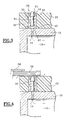
- FIGS. 7A and 7B a locking variant has been shown. manual, identical references bearing the same increased references of 100.
- This variant provides a movable valve 136 which is pushed by a spring 154 as in the previous assembly.
- the ring 138 is identical to the previous ring 38, with an internal passage 140 with a hexagon for allow the body 150 of the valve to slide.
- This body 150 has a end 151 which is of form conjugate with that of the hole made in the support cylinder 10 for indexing.
- the ring 144 of the seat 134 is of simple shape with passage 148 inside cylindrical, combined with that of the body 150 of the valve.
- a collar 153 forming a stop is added to the body and secured to it to avoid passage of this body 150 of the valve through the passage 148 and especially for form a seal with the face opposite the seat 134.
- This arrangement also provides means 160 for locking in position which include a pin 162, arranged transversely to the body 150 of the valve, immediately above the flange 153, provided to cooperate with an open housing 164, of a shape adapted to receive this pin in a given first angular position.
- valve In this position shown in Figure 7A, the valve is in position high and the collar seals with the face opposite the ring 144 of the seat 134.
- the pressurized air reinforces this plating effect.
- an air film is formed between the sleeve 22 and this cylinder support 10, in the case where the enclosure 16 constituted by the hollow interior of the support cylinder is supplied with pressurized air.
- the valve When the sleeve must be immobilized, it is enough, after positioning the sleeve relative to the support cylinder by means of external marks, rotate the valve, using a simple screwdriver blade for example, a slot 166 being formed at the end of the valve on the head 152.
- the valve once turned angularly, has an offset between the pin 162 and the housing 164 provided for receiving it, so that the valve is kept in the open position because the flange is moved away from the face of the seat ring on which it was resting.
- the end 151 of the valve body enters the hole in the support cylinder, which allows a check of the correct indexing.
- the compensation sleeve is thus positioned and immobilized on the support cylinder 10.
- the pressurized air admitted into the enclosure 16 constituted by the hollow body of this cylinder passes through the sleeve of compensation which allows the mounting of the printing sleeve with its snapshot, easily, as in the main embodiment.
- the sealing means are mounted directly on the support cylinder because this improves the pressure distribution and makes it possible to obtain an air film of best quality.
- the shutters are then directly introduced into the thickness of the cylinder.
- an insert which is screwed into a threaded hole machined in the thickness of the wall of the cylinder, said insert comprising all of the elements support / seat / valve / spring which have just been described for the sleeve compensation.
- valve can be produced by means a valve according to the invention because it suffices to orient the assembly support / seat / valve upside down and mount a stiffer spring, calibrated to correspond to a given maximum pressure.
Landscapes
- Supply, Installation And Extraction Of Printed Sheets Or Plates (AREA)
- Self-Closing Valves And Venting Or Aerating Valves (AREA)
Claims (9)
- Vorrichtung zum automatischen Verschließen von Luftdurchgangslöchern in einem Zylinder, insbesondere für Trägerzylinder (10) von Hülsen und für Ausgleichshülsen (22), die in der Wandstärke dieses Zylinders eingelassen einen Träger (32) mit Innendurchgang (40), einen Sitz (34) und ein Ventil (36) enthält, das im Träger verschiebbar ist und zwei Stellungen einnehmen kann, nämlich eine erste, in der das Ventil in Dichtkontakt mit dem genannten Sitz gelangt, und eine weitere, in der es zurückgesetzt ist, so dass es einen Durchgang freigibt, dadurch gekennzeichnet, dass das Ventil (36) einen kegelförmigen Teller (52) aufweist und der Sitz (34) mit einem Innendurchgang (48) versehen ist, dessen Form der des Tellers entspricht, um eine Dichtheit dann zu gewährleisten, wenn der Teller im Innendurchgang geringfügig bezüglich der Außenfläche vorspringend am Sitz anliegt, und eine Stellung, in welcher der Teller bezüglich dem Sitz zurückgesetzt ist und dabei einen Durchgang freigibt.
- Vorrichtung zum automatischen Verschließen von Luftdurchgangslöchern in einem Zylinder, insbesondere für Trägerzylinder (10) von Hülsen und für Ausgleichshülsen (22), die in der Wandstärke dieses Zylinders eingelassen einen Träger (132) mit Innendurchgang (140), einen Sitz (134) und ein Ventil (136) enthält, das im Träger verschiebbar ist und zwei Stellungen einnehmen kann, nämlich eine erste, in der das Ventil in Dichtkontakt mit dem genannten Sitz gelangt, und eine weitere, in der es so zurückgesetzt ist, dass es einen Durchgang freigibt, dadurch gekennzeichnet, dass das Ventil (136) einen Teller (152) mit einem Bund (153) aufweist, der dazu vorgesehen ist, sich in dichter Weise an der dem Sitz (134) gegenüberliegenden Seite anzulegen, sowie ein Teil (162, 164), das einen Winkelbewegungsanschlag bildet, so dass die Dichtheit dann gewährleistet ist, wenn das Anschlagteil sich in einer ersten Winkelstellung befindet, und ein Durchgang durch Zurücksetzen des Bundes gegenüber dem Sitz gebildet ist, wenn das Anschlagteil sich in einer zweiten Winkelstellung befindet.
- Vorrichtung zum automatischen Verschließen von Luftdurchgangslöchern nach Anspruch 2, dadurch gekennzeichnet, dass das Anschlagteil ein quer zum Ventil verlaufender Stift (162) ist, der dazu vorgesehen ist, sich in eine offene Aufnahme (164) einzuschieben, die in der dem Sitz gegenüberliegenden Seite ausgeführt ist.
- Vorrichtung zum automatischen Verschließen von Luftdurchgangslöchern nach Anspruch 2 oder 3, dadurch gekennzeichnet, dass der Ventilteller einen Schlitz (166) aufweist, der dazu bestimmt ist, mit einer Betätigungsschneide von außen durch einen inneren Durchgang (148) des Sitzes (134) zusammenzuwirken.
- Vorrichtung zum automatischen Verschließen von Luftdurchgangslöchern nach einem der vorangehenden Ansprüche, dadurch gekennzeichnet, dass sie eine Rückholfeder (54, 154) aufweist, die zwischen dem Träger und dem Ventil eingesetzt ist und eine Kraft radial von innen nach außen ausübt.
- Vorrichtung zum automatischen Verschließen von Luftdurchgangslöchern nach einem der vorangehenden Ansprüche, dadurch gekennzeichnet, dass die verschiedenen Teile wie Träger, Sitz, Ventil, in einem Einsatz angebracht sind, der dazu vorgesehen ist, in die Wandstärke des Zylinders eingesetzt zu werden.
- Anordnung mit einem Trägerzylinder (10) und einer Hülse, die dazu bestimmt ist, koaxial zum Trägerzylinder gelagert zu werden, wie etwa eine Druckhülse, mit Zwischenlagerung einer Ausgleichshülse, wobei der Trägerzylinder (10) ein Hohlzylinder ist, dessen Innenraum (16) mit einer Druckluftquelle (15) verbindbar ist, und Düsensätze (18, 20) enthält, die über seinem Umfang verteilt sind, wobei die Ausgleichshülse (22) Düsensätze (24, 26) enthält, die so verteilt sind, dass sie mit den Düsensätzen im Trägerzylinder übereinstimmen, wobei automatische Verschließvorrichtungen in die in der Ausgleichshülse ausgeführten Düsen eingefügt sind, die einen Träger (32) mit Innendurchgang (40), einen Sitz (34) und ein Ventil (36) enthalten, das im Träger verschiebbar ist und zwei Stellungen einnehmen kann, nämlich eine erste, in der das Ventil in Dichtkontakt mit dem genannten Sitz gelangt, und eine weitere, in der es so zurückgesetzt ist, dass es einen Durchgang freigibt, wobei das Ventil (36) einen kegelförmigen Teller (52) aufweist und der Sitz (34) mit einem Innendurchgang (48) versehen ist, dessen Form der des Tellers entspricht, um eine Dichtheit dann zu gewährleisten, wenn der Teller im Innendurchgang geringfügig gegenüber der Außenfläche vorspringend am Sitz anliegt, und eine Stellung, in welcher der Teller gegenüber dem Sitz zurückgesetzt ist und dabei einen Durchgang freigibt, wobei dieser Versatz gegenüber dem Sitz durch die zylindrische Innenseite der auf die Ausgleichshülse aufgesteckten Druckhülse bewirkt wird.
- Anordnung nach Anspruch 7, dadurch gekennzeichnet, dass der Trägerzylinder (10) mit Sicherheitsventilen versehen ist, die auf einen maximalen Sicherheitsdruck geeicht sind, oberhalb dessen die Druckluft ausweicht.
- Anordnung nach Anspruch 7 oder 8, dadurch gekennzeichnet, dass ein Ring aus Fasermaterial, wie etwa ein Ring aus Filz, am Ende des Trägerzylinders (10) angeordnet ist, an dem die Ausgleichshülse (22) am Trägerzylinder aufgesteckt ist, und der darauf abgestimmt ist, eine Reinigung der Innenfläche der Hülse bei deren Aufstecken zu gewährleisten.
Applications Claiming Priority (2)
| Application Number | Priority Date | Filing Date | Title |
|---|---|---|---|
| FR9811710A FR2783201B1 (fr) | 1998-09-15 | 1998-09-15 | Dispositif d'obturation automatique de trous de passage d'air dans un cylindre, notamment pour les cylindres supports et les manchons de compensation |
| FR9811710 | 1998-09-15 |
Publications (2)
| Publication Number | Publication Date |
|---|---|
| EP0987109A1 EP0987109A1 (de) | 2000-03-22 |
| EP0987109B1 true EP0987109B1 (de) | 2003-04-09 |
Family
ID=9530616
Family Applications (1)
| Application Number | Title | Priority Date | Filing Date |
|---|---|---|---|
| EP19990450021 Expired - Lifetime EP0987109B1 (de) | 1998-09-15 | 1999-09-15 | Automatische Dichtungsvorrichtung für Luftdurchgangslöchern in einem Zylinder, insbesondere für Trägerzylindern und Kompensationshülse |
Country Status (3)
| Country | Link |
|---|---|
| EP (1) | EP0987109B1 (de) |
| DE (1) | DE69906652T2 (de) |
| FR (1) | FR2783201B1 (de) |
Families Citing this family (4)
| Publication number | Priority date | Publication date | Assignee | Title |
|---|---|---|---|---|
| US6276271B1 (en) * | 2000-03-17 | 2001-08-21 | Day International, Inc. | Bridge mandrel for flexographic printing systems |
| US6360662B1 (en) | 2000-03-17 | 2002-03-26 | Day International, Inc. | Bridge mandrel for flexographic printing systems |
| US7107907B2 (en) * | 2001-01-22 | 2006-09-19 | Goss International Americas, Inc. | Flow-restricted printing cylinder for a removable printing sleeve |
| DE102004043088A1 (de) * | 2004-09-07 | 2006-03-09 | Man Roland Druckmaschinen Ag | Sleeve für einen Druckmaschinenzylinder sowie Druckmaschinenzylinder |
Family Cites Families (1)
| Publication number | Priority date | Publication date | Assignee | Title |
|---|---|---|---|---|
| SE9101235L (sv) * | 1991-04-23 | 1992-10-24 | Miller Graphics Ab | Anordning vid tryckverk |
-
1998
- 1998-09-15 FR FR9811710A patent/FR2783201B1/fr not_active Expired - Fee Related
-
1999
- 1999-09-15 DE DE1999606652 patent/DE69906652T2/de not_active Expired - Lifetime
- 1999-09-15 EP EP19990450021 patent/EP0987109B1/de not_active Expired - Lifetime
Also Published As
| Publication number | Publication date |
|---|---|
| FR2783201A1 (fr) | 2000-03-17 |
| DE69906652D1 (de) | 2003-05-15 |
| DE69906652T2 (de) | 2004-04-08 |
| EP0987109A1 (de) | 2000-03-22 |
| FR2783201B1 (fr) | 2000-11-10 |
Similar Documents
| Publication | Publication Date | Title |
|---|---|---|
| EP1938950B1 (de) | Vorrichtung für Aufdehnwerkzeug für Zange auf der Maschine, zum Ausführen von Fugen an den Endstücken von Plastik- oder Verbundrohren | |
| WO2000032977A1 (fr) | Coupleur a billes | |
| FR2831940A1 (fr) | Raccord rapide pour la jonction amovible de deux canalisations | |
| FR2540959A1 (fr) | Dispositif distributeur de fluide, notamment pour telecommande | |
| FR2947596A1 (fr) | Insert taraude pour alesage cylindrique et equipement d'installation d'un tel insert | |
| FR2872717A1 (fr) | Pistolet de pulverisation automatique comprenant un corps de pulverisation monte sur une embase d'alimentation | |
| EP0987109B1 (de) | Automatische Dichtungsvorrichtung für Luftdurchgangslöchern in einem Zylinder, insbesondere für Trägerzylindern und Kompensationshülse | |
| EP0765197B1 (de) | Vorrichtung zum einzelfördern von werkstücken und vorratsbehälter für werkstücke | |
| FR2947318A1 (fr) | Vanne a obturateur pour un dispositif d'accouplement de conduits | |
| EP1525096A2 (de) | Verbesserungen in druckmaschinen | |
| EP4180093B1 (de) | Flüssigkeitskupplungsvorrichtung mit visuellem indikator | |
| EP0667461B1 (de) | Präzisionsbefestigung zwischen zwei Teilen | |
| FR2511281A1 (fr) | Dispositif de retenue d'un corps rotatif autour d'un axe non coaxial a son arbre d'entrainement | |
| FR2746462A1 (fr) | Procede et dispositif permettant de fixer axialement une bague a un arbre | |
| EP1183153B1 (de) | Druckmaschinenzylinder mit indexierungsmitteln zum anbringen einer druckhülse an dem trägerzylinder | |
| FR3089441A1 (fr) | Dispositif de solidarisation d’un dispositif de perçage à une grille de perçage comprenant un moyeu expansible à billes | |
| EP0855268A1 (de) | Vorrichtung zum Fixieren von einer Druckhülse auf einem Druckwalzenkern | |
| EP3623101A1 (de) | Zentrierwerkzeug für bohrungen und zentrierverfahren für bohrungen einer motorbefestigung eines luftfahrzeugs, die ein solches zentrierwerkzeug verwendet | |
| EP0683046A1 (de) | Vorrichtung zum Befestigen von Druckplatten auf Trägerzylindern von Flexodruckmaschinen | |
| FR2785226A1 (fr) | Manchon intermediaire pour cylindre d'impression | |
| FR2885068A1 (fr) | Dispositif mecanique de fixation amovible d'un manchon sur un arbre porteur d'une machine a imprimer | |
| FR2742379A1 (fr) | Dispositif de fixation d'un manchon sur un axe d'un cylindre porte-cliches | |
| FR2749215A1 (fr) | Machine a imprimer a detecteur de presence associe a un support porte-objet | |
| EP1160027A1 (de) | Aufweitzange | |
| FR2789626A1 (fr) | Dispositif d'obturation de trous de passage d'air dans un cylindre, notamment pour les cylindres supports et les manchons de compensation |
Legal Events
| Date | Code | Title | Description |
|---|---|---|---|
| PUAI | Public reference made under article 153(3) epc to a published international application that has entered the european phase |
Free format text: ORIGINAL CODE: 0009012 |
|
| AK | Designated contracting states |
Kind code of ref document: A1 Designated state(s): DE ES FR GB IT |
|
| AX | Request for extension of the european patent |
Free format text: AL;LT;LV;MK;RO;SI |
|
| 17P | Request for examination filed |
Effective date: 20000405 |
|
| AKX | Designation fees paid |
Free format text: DE ES FR GB IT |
|
| GRAG | Despatch of communication of intention to grant |
Free format text: ORIGINAL CODE: EPIDOS AGRA |
|
| 17Q | First examination report despatched |
Effective date: 20011128 |
|
| GRAG | Despatch of communication of intention to grant |
Free format text: ORIGINAL CODE: EPIDOS AGRA |
|
| GRAG | Despatch of communication of intention to grant |
Free format text: ORIGINAL CODE: EPIDOS AGRA |
|
| GRAH | Despatch of communication of intention to grant a patent |
Free format text: ORIGINAL CODE: EPIDOS IGRA |
|
| GRAH | Despatch of communication of intention to grant a patent |
Free format text: ORIGINAL CODE: EPIDOS IGRA |
|
| RAP1 | Party data changed (applicant data changed or rights of an application transferred) |
Owner name: MACDERMID HOLDING S.A.S |
|
| RIN1 | Information on inventor provided before grant (corrected) |
Inventor name: FRANCILLE, JEAN |
|
| GRAA | (expected) grant |
Free format text: ORIGINAL CODE: 0009210 |
|
| AK | Designated contracting states |
Designated state(s): DE ES FR GB IT |
|
| PG25 | Lapsed in a contracting state [announced via postgrant information from national office to epo] |
Ref country code: GB Free format text: LAPSE BECAUSE OF FAILURE TO SUBMIT A TRANSLATION OF THE DESCRIPTION OR TO PAY THE FEE WITHIN THE PRESCRIBED TIME-LIMIT Effective date: 20030409 |
|
| REG | Reference to a national code |
Ref country code: GB Ref legal event code: FG4D Free format text: NOT ENGLISH |
|
| GBV | Gb: ep patent (uk) treated as always having been void in accordance with gb section 77(7)/1977 [no translation filed] |
Effective date: 20030409 |
|
| PG25 | Lapsed in a contracting state [announced via postgrant information from national office to epo] |
Ref country code: ES Free format text: LAPSE BECAUSE OF FAILURE TO SUBMIT A TRANSLATION OF THE DESCRIPTION OR TO PAY THE FEE WITHIN THE PRESCRIBED TIME-LIMIT Effective date: 20031030 |
|
| PLBE | No opposition filed within time limit |
Free format text: ORIGINAL CODE: 0009261 |
|
| STAA | Information on the status of an ep patent application or granted ep patent |
Free format text: STATUS: NO OPPOSITION FILED WITHIN TIME LIMIT |
|
| 26N | No opposition filed |
Effective date: 20040112 |
|
| REG | Reference to a national code |
Ref country code: FR Ref legal event code: TP |
|
| PG25 | Lapsed in a contracting state [announced via postgrant information from national office to epo] |
Ref country code: IT Free format text: LAPSE BECAUSE OF NON-PAYMENT OF DUE FEES Effective date: 20090915 |
|
| PGRI | Patent reinstated in contracting state [announced from national office to epo] |
Ref country code: IT Effective date: 20110616 |
|
| REG | Reference to a national code |
Ref country code: DE Ref legal event code: R082 Ref document number: 69906652 Country of ref document: DE Representative=s name: MEISSNER BOLTE PATENTANWAELTE RECHTSANWAELTE P, DE Ref country code: DE Ref legal event code: R082 Ref document number: 69906652 Country of ref document: DE Representative=s name: MEISSNER, BOLTE & PARTNER GBR, DE |
|
| PGFP | Annual fee paid to national office [announced via postgrant information from national office to epo] |
Ref country code: FR Payment date: 20140901 Year of fee payment: 16 |
|
| PGFP | Annual fee paid to national office [announced via postgrant information from national office to epo] |
Ref country code: IT Payment date: 20140918 Year of fee payment: 16 |
|
| PGFP | Annual fee paid to national office [announced via postgrant information from national office to epo] |
Ref country code: DE Payment date: 20141127 Year of fee payment: 16 |
|
| REG | Reference to a national code |
Ref country code: DE Ref legal event code: R119 Ref document number: 69906652 Country of ref document: DE |
|
| PG25 | Lapsed in a contracting state [announced via postgrant information from national office to epo] |
Ref country code: IT Free format text: LAPSE BECAUSE OF NON-PAYMENT OF DUE FEES Effective date: 20150915 |
|
| REG | Reference to a national code |
Ref country code: FR Ref legal event code: ST Effective date: 20160531 |
|
| PG25 | Lapsed in a contracting state [announced via postgrant information from national office to epo] |
Ref country code: DE Free format text: LAPSE BECAUSE OF NON-PAYMENT OF DUE FEES Effective date: 20160401 |
|
| PG25 | Lapsed in a contracting state [announced via postgrant information from national office to epo] |
Ref country code: FR Free format text: LAPSE BECAUSE OF NON-PAYMENT OF DUE FEES Effective date: 20150930 |