EP0987183A1 - Transport- und Schaustellungsbehälter - Google Patents
Transport- und Schaustellungsbehälter Download PDFInfo
- Publication number
- EP0987183A1 EP0987183A1 EP99117939A EP99117939A EP0987183A1 EP 0987183 A1 EP0987183 A1 EP 0987183A1 EP 99117939 A EP99117939 A EP 99117939A EP 99117939 A EP99117939 A EP 99117939A EP 0987183 A1 EP0987183 A1 EP 0987183A1
- Authority
- EP
- European Patent Office
- Prior art keywords
- package
- side wall
- blank
- segment
- bottom wall
- Prior art date
- Legal status (The legal status is an assumption and is not a legal conclusion. Google has not performed a legal analysis and makes no representation as to the accuracy of the status listed.)
- Granted
Links
Images


Classifications
-
- B—PERFORMING OPERATIONS; TRANSPORTING
- B65—CONVEYING; PACKING; STORING; HANDLING THIN OR FILAMENTARY MATERIAL
- B65D—CONTAINERS FOR STORAGE OR TRANSPORT OF ARTICLES OR MATERIALS, e.g. BAGS, BARRELS, BOTTLES, BOXES, CANS, CARTONS, CRATES, DRUMS, JARS, TANKS, HOPPERS, FORWARDING CONTAINERS; ACCESSORIES, CLOSURES, OR FITTINGS THEREFOR; PACKAGING ELEMENTS; PACKAGES
- B65D5/00—Rigid or semi-rigid containers of polygonal cross-section, e.g. boxes, cartons or trays, formed by folding or erecting one or more blanks made of paper
- B65D5/42—Details of containers or of foldable or erectable container blanks
- B65D5/44—Integral, inserted or attached portions forming internal or external fittings
- B65D5/52—External stands or display elements for contents
- B65D5/5273—Containers provided with an inclined surface on which the contents are located
-
- B—PERFORMING OPERATIONS; TRANSPORTING
- B65—CONVEYING; PACKING; STORING; HANDLING THIN OR FILAMENTARY MATERIAL
- B65D—CONTAINERS FOR STORAGE OR TRANSPORT OF ARTICLES OR MATERIALS, e.g. BAGS, BARRELS, BOTTLES, BOXES, CANS, CARTONS, CRATES, DRUMS, JARS, TANKS, HOPPERS, FORWARDING CONTAINERS; ACCESSORIES, CLOSURES, OR FITTINGS THEREFOR; PACKAGING ELEMENTS; PACKAGES
- B65D5/00—Rigid or semi-rigid containers of polygonal cross-section, e.g. boxes, cartons or trays, formed by folding or erecting one or more blanks made of paper
- B65D5/42—Details of containers or of foldable or erectable container blanks
- B65D5/44—Integral, inserted or attached portions forming internal or external fittings
- B65D5/50—Internal supporting or protecting elements for contents
- B65D5/5002—Integral elements for containers having tubular body walls
- B65D5/5007—Integral elements for containers having tubular body walls formed by inwardly protruding of folded parts of the body
Definitions
- the present invention relates generally to containers and particularly to packages which are folded from a single package blank and to package blanks as such. These packages comprise at least one inclined wall and can conveniently be used for storing, shipping and for shop presentation, especially in connection with foodstuff, in particular square or rectangular packages of cheese, breakfast cereals, bars of confectionery, such as chocolate bars, etc.
- the inclined wall typically the back wall of the package
- the inclined wall was formed by providing a double layered wall.
- the outer layer of this double layered back wall was oriented perpendicularly to the bottom wall, and the inner layer of this double layered back wall extended between the upper edge of the outer layer and a base line on the bottom wall.
- the angle of inclination of the inner layer could be pre-selected.
- US 2,132,604 discloses a display package which is manufactured from a single package blank.
- the package comprises a multi-layered side wall at the back side of the display package.
- Several layers facing the inside of the package are inclined and form an obtuse angle with the bottom wall.
- These inclined layers of the backside wall support the contents of the box during shipping and display.
- An automatized folding of the package blank and packing operation are not contemplated.
- this problem is solved by a package in accordance with claim 1.
- Advantageous embodiments of this package are described in the dependent claims 2 to 7.
- the invention provides significant advantages over previously known packages and blanks therefor.
- the design is such that the packages comprise a plurality of side walls, at least one of which is at least partially a single-layered support side wall.
- This support side wall provides support for the products to be packaged, i.e. these products typically rest with a point or line of contact with the bottom wall against at least part of the support side wall.
- this part of the support side wall forms an obtuse angle with the bottom wall. It is also contemplated that substantially the entire support side wall is formed into this obtuse angle.
- the plurality of side walls or side wall segments which may define any chosen cross-sectional shape, i.e.
- a bottom wall and a top are provided so as to enclose a package space.
- This package space does not necessarily need to be enclosed by contiguous wall segments without any gaps and/or openings. Rather, the configuration in this respect should be designed to fulfil requirements as regards preventing loss of the package contents, providing the required ventilation as well as sufficient surface area to provide the outside of the package with the desired imprints, such as expiration dates, logos, etc. Erection of the package from the blank and the package's stability is ensured in accordance with the invention by the necessary flaps and tabs so as to permit, by folding and attaching, formation of the package from the blank.
- a further side wall of the inventive package is at least partially removable. Additionally, at least part of the top can be removable. Removal of the removable part of the support side wall and, if applicable, that of the top, provides access to the package space.
- Such removal can be enabled by suitable design measures such as weakening lines. At present, perforations are preferred.
- the support side wall is at least partially single-layered. This opens up the possibility to automatize the folding and packaging operation.
- the support side wall forms in a single-layered portion an obtuse angle with the bottom wall and supports the contents of the box during shipping and display.
- a protrusion towards the inside of the display package is formed. This protrusion can be pushed in from the outside of the folded package which opens up the possibility for an easy automatization of the production and packaging process.
- a preferred embodiment of the invention suggests, in combination with at least one product to packed, that the obtuse angle is selected so that a perpendicular which is dropped from the center of gravity of the product to the plane of the bottom wall, passes through the support side wall.
- this product should be directly adjacent to the support side wall. This feature advantageously ensures that even without any further action of locking the package contents, the package securely rests against the obtusely inclined side wall and the bottom wall.
- a further preferred feature of the inventive solution contributes to the locking of the package contents.
- the further side wall opposite the support side wall is single-layered and at least part thereof forms an acute angle with the bottom wall.
- this further side wall is, relative to the bottom wall, at least partially inclined in the same direction as the support side wall.
- substantially the entire further side wall is formed into this acute angle.
- Packaging and transport of stackable goods is considerably enhanced, since the goods are form-locked between the obtusely and the acutely inclined portions of the respective walls.
- it is also possible to extend this feature to walls adjacent to the respective side walls such as top wall segments and/or bottom wall segments.
- the degree of acuteness of the acute angle is higher than the degree of obtuseness of the obtuse angle.
- the difference between the acute angle and the perpendicular to the bottom wall is greater than the difference between the obtuse angle and a perpendicular to the bottom wall.
- This feature facilitates ease of manufacture since it enables a line of contact of the acute portion with the packaged product rather than surface area contact and, therefore, permits the enlarging of the tolerances for the wall and/or wall segment dimensions.
- this preferred embodiment clearly defines the two walls to be non-parallel, it is in accordance with the broader aspects of the invention also possible to make use of opposite side walls that are inclined and parallel to one another.
- the obtuse and/or acute side walls can be formed by various means and methods known to persons having skill in the art.
- the obtuse angle of the single-layered support side wall and the acute angle of the further single-layered side wall are formed by parts thereof projecting to the inside of the package. It is at present preferred to provide the side walls or additionally the adjacent top and bottom wall of the package with elongate openings, typically cuts, so that the portion of the respective walls between the cuts can be folded inwardly so as to form the angled walls. This folding can advantageously take place in-line during formation of the package from the blank.
- planar goods are to be understood as two dimensional goods or three-dimensional goods with a thickness that is small in comparison to the length and the breadth.
- the most efficient use of the package space provided by a package that is easy to form is made by using the inventive package for packing foodstuff, in particular square or rectangular packages of cheese, breakfast cereals, bars of confectionery, such as chocolate bars, etc.
- the inventive package blank referred to above preferably provides that at least part of the support side wall segment is arrangeable, in the folded disposition of the blank, so as to form an obtuse angle with the bottom wall segment.
- the side wall segment for formation of the outer wall of the package as well as the inclined support wall, waste of material in the production of blanks is advantageously reduced.
- at least part of at least one further side wall segment or additionally of the at least one top segment is or are removable to provide, by removal in the folded disposition of the blank, access to the package space.
- this design permits the production of the inventive package blank in a one-step operation.
- the present invention advantageously further provides that the inventive blank is punched from one piece.
- filling of the inventive package takes place in-line upon formation of the package from the blank.
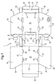
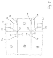
- FIG. 1 A shipping and display package according to a first embodiment of the present invention is shown in Fig. 1 in plan view in its configuration after manufacture of the blank.
- a front wall attachment flap 12 which forms, in the folded disposition of the blank, an inclined front wall, a top wall segment 16, rear wall segments 20 and 22, a bottom wall segment 26, an outer front wall segment 40 and, finally, an inner front wall segment 38.
- Top wall segment 16 extends in Fig. 1 to the top and bottom into outer side wall segments 18. These outer side wall segments 18 are provided with inclined edges 19, the function of which will be discussed in greater detail below.
- Rear wall segment 20 extends, in Fig. 1 to the top and bottom, into side wall enforcement flaps 24.
- Bottom wall segment 26 in turn, extends to the top and bottom into inner side wall segments 28 which are provided with inclined edges 29, the function of which will also be discussed in greater detail below.
- To the left and right of the respective inner side wall segments 28 are rear wall locking flaps 30 with tongues 32 and front wall enforcement flaps 36, respectively.
- crease lines or fold lines are located within the various wall segments and are adapted to enable folding of adjacent segments along these lines, substantially without deformation of the respective segments. A skilled person will be aware as to how to best embody this function.
- side wall segments 18 and 28 are of approximately equal size.
- the dimensions of front attachment flap 12 substantially correspond to the dimensions of the front wall segments 38,40. Upon manufacture of the package from the blank in accordance with the first embodiment of the present invention, these segments come to overly one another, so that this dimensioning maintains ease of fabrication.
- arrow A indicates how the rear wall portion 22 is folded away from the rear wall segment 20.
- This infolding of segments 22 and 23 into what will become the interior of the package in the folded disposition of the blank, does not necessarily need to be the first step in the formation of the package.
- this step as indicated by arrow A should be carried out before the respective side wall segments are folded and provide the blank with initial stability.
- Foldable wall segment 22 is foldable on account of cut 27 (compare Fig. 1). Further, recesses between the wall segments 22, 23 maintain a precise definition of fold lines.
- Arrow B indicates a subsequent folding step during which side wall enforcement flaps 24 are folded upwards along their respective crease or fold lines.
- rear wall segment 20 together with top wall segment 16, side wall segment 18 and the inclined front wall segment 14 are folded upwards so that the side wall reinforcement flaps 24 are located adjacent to the fold lines between inner side wall segments 28 and the bottom wall segment 26.
- This folding step also causes the foldable portion 23 of the bottom wall segment 26 to approach the non-foldable portion of the latter and to assume a position substantially parallel thereto. Accordingly, the obtuse angle of the folded rear wall portion 22 relative to the bottom wall segment 26 in the folded disposition of the blank is achieved, as will be noted in connection with Fig. 3.
- the inner side wall segments 28 are folded upwardly and the rear wall locking flaps 30 are folded so that they reach around the unfolded portion 20 of the rear wall that is not folded inwardly. Subsequently, tongues 32 of the rear wall locking flap are inserted into their corresponding recesses 34. During or after this folding step, the front wall enforcement flaps 36 are also folded upwardly, as indicated by arrow C.
- the inner front wall segment 38 is folded upwardly, over the front wall enforcement flaps and again downwardly until the front wall locking tabs 42 are insertable into their corresponding recesses 44.
- the front wall enforcement flaps 36 come to lie between the inner front wall segment 38 and the outer segment 40 and formation of the lower part of the package is completed, as depicted in Fig. 3.
- the folded rear wall portion 22 forms an angle together with the bottom wall 26 that is obtuse, i.e. an angle greater than 90 degrees.
- the folded wall portion 22 serves as a support for product to be inserted into the pre-formed package, as will be described in more detail below.
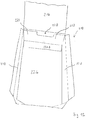
- Substantially planar products P preferably chocolate bars, are inserted into the pre-formed package as a stack, following arrow E in Fig. 3.
- the obtuse angle ⁇ is selected so that each Product P will securely rest against an adjacent product or, eventually, against the support walls 22.
- the obtuse angle ⁇ is selected such that the centre of gravity lies beyond the line of contact between support walls 22 and bottom walls 26, beyond as seen from bottom wall segment 26.
- a perpendicular is dropped from the centre of gravity of the Product P at adjacent support wall 22 to the bottom wall 26, it will pass through support wall 22.
- the top of the package is closed so as to complete formation of the package. This is done by following arrows F and G.
- Arrow F denotes how the top wall 16 and the inclined front wall 14 are lowered until the front wall attachment flap 12 can engage behind the inner front wall 38. Further engagement takes place between the front wall 14 and the inclined edges 19 and 29 of the outer and inner side walls, respectively.
- the angle of inclination is determined by the angle ⁇ between the edges 19,29 and the bottom wall 26.
- This angle ⁇ can be selected so that the inclined front wall 14 in a closed disposition of the package (compare Fig. 4) is parallel to the support wall 22.
- the preferred variation of this embodiment provides that the angle of inclination of the inclined front wall 14 is greater than that of the support wall 22. Accordingly, the front wall 14 in combination with the support wall 22 will engage with a stack of products along a line of contact in the upper region of the package and tolerance requirements during manufacture of the blank and package are reduced.
- the package is closed by applying strips of adhesive tape to the inclining front wall 14 and the side walls 18 as well as the side walls 18 and the bottom walls 26, as indicated in Fig. 4.
- the top wall of the package in accordance with the first embodiment of the present invention is provided with stacking recesses 48 and stacking tabs 50.
- the stacking tabs 50 can be folded upwardly from the top wall 16, as depicted in Fig. 4, so as to mate with corresponding stacking recesses 28 of a package stacked on top. Mating engagement between these stacking tabs 50 and stacking recesses 48 will ensure proper alignment and stability of a stack of inventive packages and, therefore, improve transport conditions and/or display.
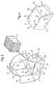
- a side wall segment 118 In the central part of Fig. 5 are depicted, as seen from left to right, a side wall segment 118, rear wall segments 120,122, a further side wall segment 118, front wall segments 113,114, and finally a package attachment flap 112.
- top wall segments 116 Extending from the various segments just described, downwardly in Fig. 5, are various top wall segments 116. Located opposite to the top wall segment and integrally joined to the side, front and rear wall segments are upper wall segments 126. As can be taken from Fig. 5, two pairs of top 116 and bottom 126 wall segments are provided with clearance recesses 119, the function of which will be discussed in greater detail below.
- the foldable support rear wall portion 122 is separated from the rear wall portion 120 by elongate openings 127.
- the foldable front wall portion 114 is separated from front wall portion 113 by elongate openings 129.
- These elongate openings 127, 129 are to be understood as alternatives to the cuts 27 described in connection with the first embodiment of the present invention. Although both of these embodiments enable the present invention to be carried out, the elongate openings are preferred since in-line filling of the package upon formation of the package from the blank is facilitated.
- the elongate openings 127,129 extend into the wall segments adjacent to the respective rear wall portion 122 and front wall portion 114, and define a foldable bottom wall portion 123 and a foldable top wall portion 115, respectively.
- perforations 146 are depicted which, in the folded disposition of the blank, are joined to form a substantially continuous weakening line.
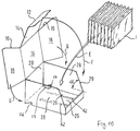
- Fig. 6 a stack of products P to be disposed in the package, in accordance with the second embodiment of the present invention, is depicted.
- Fig. 6 denotes the starting position for fully automated filling and package-formation.
- the stack of products P is disposed on the rear wall portions 120,122.
- side wall segments 118 are folded upwards and their adjacent top and bottom wall segments 116,126 inwardly, so that they abut the stack of products P.
- the top and bottom wall segments 116 and 126 adjacent to the rear wall portions 120 and 122 are folded upwardly and attached to the corresponding top and bottom wall segments adjacent to the side wall segments 118.
- the foldable rear wall portion 122 is pushed toward the interior of the pre-formed package until the disposition depicted in Fig. 7 results.
- the stack of products is tilted or inclined relative to the top wall edges visible in Fig. 7.
- the degree of this tilting inclination corresponds to the obtuse angle preselected by positioning and dimensioning the foldable rear wall portion 122 and the foldable bottom wall portion 123 to one another and to the unfolded portion 120 of the rear wall.
- the uppermost point of the stack of products P in Fig. 7 is to be flush with the upper edge of side wall segments 118.
- the foldable front wall portion 114 is folded towards the interior of the package so as to lock the products P into place.
- the innermost top and bottom wall segments are provided with clearance recesses 119 for the following reasons:
- top and bottom wall segments extending from the side wall segments 118 would interfere with the folding in of the locking front wall 114 and the support wall portion 122.
- recesses 119 are provided, as can be taken from Figs. 5 and 6.
- a further step in the in-line filling and packaging process relates to closing the pre-formed package and defining a package space therein. This is achieved by folding over the front wall segments 113 and 114 in the direction of arrow H in Fig. 7. After folding over the front wall segments 113,114, the respective top wall segments 116,126 adjacent thereto are folded downwards and suitably attached in their contact region with abutting top and bottom wall segments. Further, the package attachment flap 112 is attached to the neighbouring side wall segments 118 in order to close the package and to provide it with stability.
- this further step just described is carried out simultaneous to the step of folding the front wall portion 114 inwardly; as previously mentioned, this in-folding in connection with closing the package achieves the advantageous locking effect.
- the complete package as depicted in Fig. 8 is to be turned by 90 degrees, so that the top wall 116 faces upwards.
- the inwardly projecting inclined walls of 114,122 On account of the inwardly projecting inclined walls of 114,122, a secure support and reliable locking of the product is achieved and, simultaneously, substantially planar and symmetric outer limits of the package are obtained. Hence, the package is easy to stack and, therefore, safe transport is ensured.
- part of the front wall, part of the side walls and, additionally, part of the top wall is removed by separating along the perforation 146.
- a semi-circular opening is provided, as depicted in the drawings.
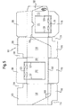
- Fig. 9 and 10 show another embodiment of the invention.
- Fig. 9 and 10 are closely related to Fig. 1 and 3 and, therefore, for the same or corresponding parts of the inventive package and the inventive package blank the same reference signs are used.
- Fig. 9 shows only a part of the package blank including the bottom wall segment 26, side wall segments 28 with a locking flap 30 and a tongue 32, respectively, and a rear wall segment 20 with side wall enforcement flaps 24 and recesses 34 for receiving the tongues 32.
- There are two cuts 56 which are perpendicular to the fold line between the bottom wall segment 26 and the side wall segments 28 in a region near to the crossing 60 of the fold line between the rear wall segment 20 and bottom wall segment 26 on the one hand and on the other hand, the bottom wall segment 26 and the side wall segments 28, respectively.
- the crossing 60 forms the corner of the folded package.
- fold lines 58 connecting the crossing 60 with the respective ends of the cuts 56, as can be seen from Fig. 9.
- protrusions 55 serve as a stop against which the lower portions of the rear most product come into an abutting engagement. This ensures that the lower edge of the rear most product is always spaced a predetermined distance from the lower edge between the bottom wall 26 and the rearward side wall 20 of the display package. This allows the products P to be packaged to be stored in the desired, inclined position.
- the bottom wall there is a certain pattern of surface regions of the bottom wall which are treated in a way to enhance the friction between the products P and the inner surface of the bottom wall 26. This higher friction can be achieved by different surface treatments.
- a preferred possibility is the application of an adhesive on certain regions of the inner bottom wall which serve to prevent the sliding of the products in the display package.
- the adhesive is a hot-meld adhesive and applied in one or more, preferably two, longitudinal tracks 62 between the rearward side surface 20 and the front surface of the display package.
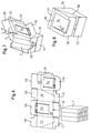
- Fig. 11 and 12 show jet another embodiment of the invention.
- the shipping and display package 210 shown in Fig. 12 is formed from a blank 201 which is shown in Fig. 11.
- the blank has a bottom wall segment 226, side wall segments 228 and a rear wall segment 220 integrally formed with a top wall segment 216. Additionally, rear wall segments 230 are contiguous to the side wall segments 228, leaving in the folded state a space of thickness d, the effect of which together with the rear wall segment 220 will be explained later.
- H2 is higher than H1.
- fold lines 222 which are parallel to the fold line between the bottom segment 226 and the rear wall segment 220 extend over the rear wall segment and can be used to fold part of the rear wall segment 220, namely the portions 220a and 220b into the interior of the display package.
- the remaining portion of the rear wall segment has a height of H3 corresponding to the height H3 of the rear wall segments 230. Therefore, the blank 210 can be folded so that the upper edges 229 of the side wall segments and 231 of the bottom wall segments have the same height over the bottom wall segment 226 as the fold line 221 between the rear wall segment 220 and the top wall segment 216.
- the rear wall portion of the display package looks like that given in Fig. 12.
- the portions 220a (not to be seen in Fig. 12) and 220b project into the interior of the package 210 and serve as a stop which allows the products to be shipped and displayed to lie angularly to the direction perpendicular to the bottom wall 226.
- again measures can be taken to increase the friction between the bottom wall 226 and the products to be displayed.
- two tracks 262 of a hot-melt adhesive are applied to the bottom surface 226.
- protrusions are formed which project into the interior of the display packages. These protrusions are formed from the material available to build up the display packages. Moreover, all protrusions are placed into regions of one of the side walls, where these side walls are single-layered. This makes it possible to form the protrusions simply by pushing in the respective portions from the outside of the package into the inside thereof. Therefore, optimum use is made of the material for forming the single-piece blanks and, moreover, the forming of the protrusions can easily be automatized because it is not necessary to perform complicated folding operations within the interior of the packages.
Landscapes
- Engineering & Computer Science (AREA)
- Mechanical Engineering (AREA)
- Cartons (AREA)
- Packages (AREA)
- Holo Graphy (AREA)
- Vending Machines For Individual Products (AREA)
Priority Applications (2)
| Application Number | Priority Date | Filing Date | Title |
|---|---|---|---|
| EP99117939A EP0987183B9 (de) | 1998-09-14 | 1999-09-14 | Transport- und Schaustellungsbehälter |
| DK99117939T DK0987183T3 (da) | 1998-09-14 | 1999-09-14 | Forsendelses- og udstillingsemballage |
Applications Claiming Priority (3)
| Application Number | Priority Date | Filing Date | Title |
|---|---|---|---|
| EP98117364A EP0987182A1 (de) | 1998-09-14 | 1998-09-14 | Transport- und Schaustellungsbehälter |
| EP98117364 | 1998-09-14 | ||
| EP99117939A EP0987183B9 (de) | 1998-09-14 | 1999-09-14 | Transport- und Schaustellungsbehälter |
Publications (3)
| Publication Number | Publication Date |
|---|---|
| EP0987183A1 true EP0987183A1 (de) | 2000-03-22 |
| EP0987183B1 EP0987183B1 (de) | 2004-06-23 |
| EP0987183B9 EP0987183B9 (de) | 2004-12-29 |
Family
ID=8232627
Family Applications (2)
| Application Number | Title | Priority Date | Filing Date |
|---|---|---|---|
| EP98117364A Withdrawn EP0987182A1 (de) | 1998-09-14 | 1998-09-14 | Transport- und Schaustellungsbehälter |
| EP99117939A Expired - Lifetime EP0987183B9 (de) | 1998-09-14 | 1999-09-14 | Transport- und Schaustellungsbehälter |
Family Applications Before (1)
| Application Number | Title | Priority Date | Filing Date |
|---|---|---|---|
| EP98117364A Withdrawn EP0987182A1 (de) | 1998-09-14 | 1998-09-14 | Transport- und Schaustellungsbehälter |
Country Status (7)
| Country | Link |
|---|---|
| EP (2) | EP0987182A1 (de) |
| AT (1) | ATE269814T1 (de) |
| DE (1) | DE69918237T2 (de) |
| DK (1) | DK0987183T3 (de) |
| ES (1) | ES2221278T3 (de) |
| NO (1) | NO325028B1 (de) |
| PT (1) | PT987183E (de) |
Cited By (3)
| Publication number | Priority date | Publication date | Assignee | Title |
|---|---|---|---|---|
| GB2407083A (en) * | 2001-07-31 | 2005-04-20 | Sca Packaging Ltd | Carton having a tray with an inclined rear wall |
| KR20120055567A (ko) * | 2009-08-26 | 2012-05-31 | 가부시키가이샤 롯데 | 포장 용기 |
| JP2012166798A (ja) * | 2011-02-10 | 2012-09-06 | Kureha Corp | 包装展示兼用箱 |
Families Citing this family (4)
| Publication number | Priority date | Publication date | Assignee | Title |
|---|---|---|---|---|
| DE102009014838B4 (de) * | 2009-03-27 | 2020-08-13 | Thimm Verpackung Gmbh + Co. Kg | Transport- und Verkaufsverpackung sowie Verfahren zur Verpackung von Produkten |
| KR200476097Y1 (ko) * | 2013-04-04 | 2015-01-29 | 주식회사 오리온 | 간지를 포함하는 접이식 포장상자 |
| FR3014083B1 (fr) * | 2013-11-29 | 2016-07-01 | Saica Pack Sl | Emballage comportant des butees a mise en volume automatique |
| DE102020112098A1 (de) | 2020-05-05 | 2021-11-11 | Syntegon Packaging Technology Gmbh | Zuschnitt für eine Verpackung, die von einer Transportkonfiguration in eine Ausstellungskonfiguration umwandelbar ist, Verfahren zur Herstellung der Verpackung aus dem Zuschnitt sowie die Verpackung selbst |
Citations (4)
| Publication number | Priority date | Publication date | Assignee | Title |
|---|---|---|---|---|
| US2132604A (en) * | 1937-01-27 | 1938-10-11 | Vick Chemical Company | Carton |
| US2260428A (en) * | 1938-05-03 | 1941-10-28 | Worcester Paper Box Corp | Display carton |
| DE3835359C1 (en) * | 1988-10-17 | 1989-10-05 | Herzberger Papierfabrik Ludwig Osthushenrich Gmbh & Co Kg, 3420 Herzberg, De | Collapsible display box |
| FR2675774A1 (fr) * | 1991-04-26 | 1992-10-30 | Socar | Emballage en un materiau semi-rigide pour le conditionnement d'objets susceptibles de se deplacer dans l'emballage. |
-
1998
- 1998-09-14 EP EP98117364A patent/EP0987182A1/de not_active Withdrawn
-
1999
- 1999-09-14 AT AT99117939T patent/ATE269814T1/de not_active IP Right Cessation
- 1999-09-14 ES ES99117939T patent/ES2221278T3/es not_active Expired - Lifetime
- 1999-09-14 DK DK99117939T patent/DK0987183T3/da active
- 1999-09-14 DE DE69918237T patent/DE69918237T2/de not_active Expired - Fee Related
- 1999-09-14 PT PT99117939T patent/PT987183E/pt unknown
- 1999-09-14 NO NO19994451A patent/NO325028B1/no not_active IP Right Cessation
- 1999-09-14 EP EP99117939A patent/EP0987183B9/de not_active Expired - Lifetime
Patent Citations (4)
| Publication number | Priority date | Publication date | Assignee | Title |
|---|---|---|---|---|
| US2132604A (en) * | 1937-01-27 | 1938-10-11 | Vick Chemical Company | Carton |
| US2260428A (en) * | 1938-05-03 | 1941-10-28 | Worcester Paper Box Corp | Display carton |
| DE3835359C1 (en) * | 1988-10-17 | 1989-10-05 | Herzberger Papierfabrik Ludwig Osthushenrich Gmbh & Co Kg, 3420 Herzberg, De | Collapsible display box |
| FR2675774A1 (fr) * | 1991-04-26 | 1992-10-30 | Socar | Emballage en un materiau semi-rigide pour le conditionnement d'objets susceptibles de se deplacer dans l'emballage. |
Cited By (4)
| Publication number | Priority date | Publication date | Assignee | Title |
|---|---|---|---|---|
| GB2407083A (en) * | 2001-07-31 | 2005-04-20 | Sca Packaging Ltd | Carton having a tray with an inclined rear wall |
| GB2407083B (en) * | 2001-07-31 | 2005-10-12 | Sca Packaging Ltd | Packaging |
| KR20120055567A (ko) * | 2009-08-26 | 2012-05-31 | 가부시키가이샤 롯데 | 포장 용기 |
| JP2012166798A (ja) * | 2011-02-10 | 2012-09-06 | Kureha Corp | 包装展示兼用箱 |
Also Published As
| Publication number | Publication date |
|---|---|
| PT987183E (pt) | 2004-10-29 |
| EP0987183B9 (de) | 2004-12-29 |
| DE69918237D1 (de) | 2004-07-29 |
| ATE269814T1 (de) | 2004-07-15 |
| DE69918237T2 (de) | 2005-07-07 |
| ES2221278T3 (es) | 2004-12-16 |
| NO325028B1 (no) | 2008-01-21 |
| EP0987182A1 (de) | 2000-03-22 |
| NO994451D0 (no) | 1999-09-14 |
| DK0987183T3 (da) | 2004-10-18 |
| EP0987183B1 (de) | 2004-06-23 |
| NO994451L (no) | 2000-03-15 |
Similar Documents
| Publication | Publication Date | Title |
|---|---|---|
| EP1136371B1 (de) | Kartonbehälter für Nahrungsmittel und Zuschnitt zur Herstellung desselben | |
| US6948617B2 (en) | Stackable container with support flanges | |
| US7658317B2 (en) | Dispensing package | |
| US9555919B2 (en) | Convertible package assembly and display system | |
| US4752029A (en) | Carton with integral display bin | |
| US5702054A (en) | Single piece food package | |
| US7051919B1 (en) | Convertible pizza box | |
| US5337951A (en) | Sturdy sandwich carton | |
| US20110127289A1 (en) | Paperboard bin-cube | |
| US6296178B1 (en) | Container with triangular corner posts | |
| US5855315A (en) | Reclosable food container | |
| EP2803594B1 (de) | Kartonzuschnitt, karton | |
| US20060060643A1 (en) | Display containers with removable panel | |
| US7410062B2 (en) | Box | |
| US20110138750A1 (en) | Convertible Pizza Box | |
| EP0987183B9 (de) | Transport- und Schaustellungsbehälter | |
| US5447269A (en) | Multiple unit box and blank therefor | |
| US20090057384A1 (en) | Carton for dispensing products and method of using the same | |
| US6227442B1 (en) | Container with integral reinforcing flange | |
| AU2020256374A1 (en) | Shipping and display container and blank for forming same | |
| GB2370034A (en) | Container formed from mutually nestable parts | |
| US20250313374A1 (en) | Container | |
| SE543091C2 (en) | Fast food packaging with Cup-holder | |
| US20040169068A1 (en) | Container with triangular corner posts | |
| JP3222034B2 (ja) | 包装箱 |
Legal Events
| Date | Code | Title | Description |
|---|---|---|---|
| PUAI | Public reference made under article 153(3) epc to a published international application that has entered the european phase |
Free format text: ORIGINAL CODE: 0009012 |
|
| AK | Designated contracting states |
Kind code of ref document: A1 Designated state(s): AT BE CH CY DE DK ES FI FR GB GR IE IT LI LU MC NL PT SE |
|
| AX | Request for extension of the european patent |
Free format text: AL;LT;LV;MK;RO;SI |
|
| 17P | Request for examination filed |
Effective date: 20000602 |
|
| AKX | Designation fees paid |
Free format text: AT BE CH CY DE DK ES FI FR GB GR IE IT LI LU MC NL PT SE |
|
| 17Q | First examination report despatched |
Effective date: 20010607 |
|
| GRAG | Despatch of communication of intention to grant |
Free format text: ORIGINAL CODE: EPIDOS AGRA |
|
| GRAG | Despatch of communication of intention to grant |
Free format text: ORIGINAL CODE: EPIDOS AGRA |
|
| GRAH | Despatch of communication of intention to grant a patent |
Free format text: ORIGINAL CODE: EPIDOS IGRA |
|
| RAP1 | Party data changed (applicant data changed or rights of an application transferred) |
Owner name: KRAFT FOODS R & D, INC. ZWEIGNIEDERLASSUNG MUENCHE |
|
| GRAG | Despatch of communication of intention to grant |
Free format text: ORIGINAL CODE: EPIDOS AGRA |
|
| GRAH | Despatch of communication of intention to grant a patent |
Free format text: ORIGINAL CODE: EPIDOS IGRA |
|
| GRAA | (expected) grant |
Free format text: ORIGINAL CODE: 0009210 |
|
| AK | Designated contracting states |
Kind code of ref document: B1 Designated state(s): AT BE CH CY DE DK ES FI FR GB GR IE IT LI LU MC NL PT SE |
|
| PG25 | Lapsed in a contracting state [announced via postgrant information from national office to epo] |
Ref country code: CY Free format text: LAPSE BECAUSE OF FAILURE TO SUBMIT A TRANSLATION OF THE DESCRIPTION OR TO PAY THE FEE WITHIN THE PRESCRIBED TIME-LIMIT Effective date: 20040623 |
|
| REG | Reference to a national code |
Ref country code: GB Ref legal event code: FG4D |
|
| REG | Reference to a national code |
Ref country code: CH Ref legal event code: EP |
|
| REG | Reference to a national code |
Ref country code: IE Ref legal event code: FG4D |
|
| REF | Corresponds to: |
Ref document number: 69918237 Country of ref document: DE Date of ref document: 20040729 Kind code of ref document: P |
|
| PG25 | Lapsed in a contracting state [announced via postgrant information from national office to epo] |
Ref country code: LU Free format text: LAPSE BECAUSE OF NON-PAYMENT OF DUE FEES Effective date: 20040914 |
|
| PG25 | Lapsed in a contracting state [announced via postgrant information from national office to epo] |
Ref country code: MC Free format text: LAPSE BECAUSE OF NON-PAYMENT OF DUE FEES Effective date: 20040930 |
|
| REG | Reference to a national code |
Ref country code: CH Ref legal event code: NV Representative=s name: E. BLUM & CO. PATENTANWAELTE |
|
| REG | Reference to a national code |
Ref country code: SE Ref legal event code: TRGR |
|
| REG | Reference to a national code |
Ref country code: DK Ref legal event code: T3 |
|
| REG | Reference to a national code |
Ref country code: GR Ref legal event code: EP Ref document number: 20040402987 Country of ref document: GR |
|
| REG | Reference to a national code |
Ref country code: PT Ref legal event code: SC4A Free format text: AVAILABILITY OF NATIONAL TRANSLATION Effective date: 20040812 |
|
| REG | Reference to a national code |
Ref country code: ES Ref legal event code: FG2A Ref document number: 2221278 Country of ref document: ES Kind code of ref document: T3 |
|
| ET | Fr: translation filed | ||
| PLBE | No opposition filed within time limit |
Free format text: ORIGINAL CODE: 0009261 |
|
| STAA | Information on the status of an ep patent application or granted ep patent |
Free format text: STATUS: NO OPPOSITION FILED WITHIN TIME LIMIT |
|
| 26N | No opposition filed |
Effective date: 20050324 |
|
| REG | Reference to a national code |
Ref country code: CH Ref legal event code: PFA Owner name: KRAFT FOODS R & D, INC. ZWEIGNIEDERLASSUNG MUENCH Free format text: KRAFT FOODS R & D, INC. ZWEIGNIEDERLASSUNG MUENCHEN#UNTERBIBERGER STRASSE 15#81737 MUENCHEN (DE) -TRANSFER TO- KRAFT FOODS R & D, INC. ZWEIGNIEDERLASSUNG MUENCHEN#UNTERBIBERGER STRASSE 15#81737 MUENCHEN (DE) |
|
| PGFP | Annual fee paid to national office [announced via postgrant information from national office to epo] |
Ref country code: PT Payment date: 20080825 Year of fee payment: 10 Ref country code: ES Payment date: 20080926 Year of fee payment: 10 Ref country code: CH Payment date: 20080930 Year of fee payment: 10 |
|
| PGFP | Annual fee paid to national office [announced via postgrant information from national office to epo] |
Ref country code: FI Payment date: 20080930 Year of fee payment: 10 Ref country code: AT Payment date: 20080820 Year of fee payment: 10 Ref country code: NL Payment date: 20080924 Year of fee payment: 10 Ref country code: IT Payment date: 20080925 Year of fee payment: 10 Ref country code: IE Payment date: 20080925 Year of fee payment: 10 Ref country code: FR Payment date: 20080917 Year of fee payment: 10 |
|
| PGFP | Annual fee paid to national office [announced via postgrant information from national office to epo] |
Ref country code: GB Payment date: 20080929 Year of fee payment: 10 |
|
| PGFP | Annual fee paid to national office [announced via postgrant information from national office to epo] |
Ref country code: DK Payment date: 20080929 Year of fee payment: 10 Ref country code: DE Payment date: 20081031 Year of fee payment: 10 |
|
| PGFP | Annual fee paid to national office [announced via postgrant information from national office to epo] |
Ref country code: SE Payment date: 20080929 Year of fee payment: 10 Ref country code: BE Payment date: 20081009 Year of fee payment: 10 |
|
| PGFP | Annual fee paid to national office [announced via postgrant information from national office to epo] |
Ref country code: GR Payment date: 20080930 Year of fee payment: 10 |
|
| REG | Reference to a national code |
Ref country code: PT Ref legal event code: MM4A Free format text: LAPSE DUE TO NON-PAYMENT OF FEES Effective date: 20100315 |
|
| BERE | Be: lapsed |
Owner name: *KRAFT FOODS R & D INC. ZWEIGNIEDERLASSUNG MUNCHEN Effective date: 20090930 |
|
| REG | Reference to a national code |
Ref country code: NL Ref legal event code: V1 Effective date: 20100401 |
|
| PG25 | Lapsed in a contracting state [announced via postgrant information from national office to epo] |
Ref country code: PT Free format text: LAPSE BECAUSE OF NON-PAYMENT OF DUE FEES Effective date: 20100315 Ref country code: FI Free format text: LAPSE BECAUSE OF NON-PAYMENT OF DUE FEES Effective date: 20090914 |
|
| REG | Reference to a national code |
Ref country code: CH Ref legal event code: PL |
|
| EUG | Se: european patent has lapsed | ||
| REG | Reference to a national code |
Ref country code: DK Ref legal event code: EBP |
|
| GBPC | Gb: european patent ceased through non-payment of renewal fee |
Effective date: 20090914 |
|
| REG | Reference to a national code |
Ref country code: IE Ref legal event code: MM4A |
|
| REG | Reference to a national code |
Ref country code: FR Ref legal event code: ST Effective date: 20100531 |
|
| PG25 | Lapsed in a contracting state [announced via postgrant information from national office to epo] |
Ref country code: AT Free format text: LAPSE BECAUSE OF NON-PAYMENT OF DUE FEES Effective date: 20090914 |
|
| PG25 | Lapsed in a contracting state [announced via postgrant information from national office to epo] |
Ref country code: NL Free format text: LAPSE BECAUSE OF NON-PAYMENT OF DUE FEES Effective date: 20100401 Ref country code: IE Free format text: LAPSE BECAUSE OF NON-PAYMENT OF DUE FEES Effective date: 20090914 Ref country code: FR Free format text: LAPSE BECAUSE OF NON-PAYMENT OF DUE FEES Effective date: 20090930 Ref country code: DE Free format text: LAPSE BECAUSE OF NON-PAYMENT OF DUE FEES Effective date: 20100401 |
|
| PG25 | Lapsed in a contracting state [announced via postgrant information from national office to epo] |
Ref country code: BE Free format text: LAPSE BECAUSE OF NON-PAYMENT OF DUE FEES Effective date: 20090930 |
|
| PG25 | Lapsed in a contracting state [announced via postgrant information from national office to epo] |
Ref country code: LI Free format text: LAPSE BECAUSE OF NON-PAYMENT OF DUE FEES Effective date: 20090930 Ref country code: GR Free format text: LAPSE BECAUSE OF NON-PAYMENT OF DUE FEES Effective date: 20100406 Ref country code: CH Free format text: LAPSE BECAUSE OF NON-PAYMENT OF DUE FEES Effective date: 20090930 |
|
| PG25 | Lapsed in a contracting state [announced via postgrant information from national office to epo] |
Ref country code: GB Free format text: LAPSE BECAUSE OF NON-PAYMENT OF DUE FEES Effective date: 20090914 |
|
| PG25 | Lapsed in a contracting state [announced via postgrant information from national office to epo] |
Ref country code: DK Free format text: LAPSE BECAUSE OF NON-PAYMENT OF DUE FEES Effective date: 20090930 |
|
| PG25 | Lapsed in a contracting state [announced via postgrant information from national office to epo] |
Ref country code: IT Free format text: LAPSE BECAUSE OF NON-PAYMENT OF DUE FEES Effective date: 20090914 |
|
| PG25 | Lapsed in a contracting state [announced via postgrant information from national office to epo] |
Ref country code: SE Free format text: LAPSE BECAUSE OF NON-PAYMENT OF DUE FEES Effective date: 20090915 |
|
| REG | Reference to a national code |
Ref country code: ES Ref legal event code: FD2A Effective date: 20110714 |
|
| PG25 | Lapsed in a contracting state [announced via postgrant information from national office to epo] |
Ref country code: ES Free format text: LAPSE BECAUSE OF NON-PAYMENT OF DUE FEES Effective date: 20110704 |
|
| PG25 | Lapsed in a contracting state [announced via postgrant information from national office to epo] |
Ref country code: ES Free format text: LAPSE BECAUSE OF NON-PAYMENT OF DUE FEES Effective date: 20090915 |