EP0987372A2 - Mécanisme de vibration et dispositif pour engendrer des vibrations dans un rouleau compresseur vibrant à amplitude variable - Google Patents
Mécanisme de vibration et dispositif pour engendrer des vibrations dans un rouleau compresseur vibrant à amplitude variable Download PDFInfo
- Publication number
- EP0987372A2 EP0987372A2 EP99124002A EP99124002A EP0987372A2 EP 0987372 A2 EP0987372 A2 EP 0987372A2 EP 99124002 A EP99124002 A EP 99124002A EP 99124002 A EP99124002 A EP 99124002A EP 0987372 A2 EP0987372 A2 EP 0987372A2
- Authority
- EP
- European Patent Office
- Prior art keywords
- vibration
- running speed
- vibration generating
- eccentric weight
- compacting roller
- Prior art date
- Legal status (The legal status is an assumption and is not a legal conclusion. Google has not performed a legal analysis and makes no representation as to the accuracy of the status listed.)
- Granted
Links
Images




Classifications
-
- B—PERFORMING OPERATIONS; TRANSPORTING
- B06—GENERATING OR TRANSMITTING MECHANICAL VIBRATIONS IN GENERAL
- B06B—METHODS OR APPARATUS FOR GENERATING OR TRANSMITTING MECHANICAL VIBRATIONS OF INFRASONIC, SONIC, OR ULTRASONIC FREQUENCY, e.g. FOR PERFORMING MECHANICAL WORK IN GENERAL
- B06B1/00—Methods or apparatus for generating mechanical vibrations of infrasonic, sonic, or ultrasonic frequency
- B06B1/10—Methods or apparatus for generating mechanical vibrations of infrasonic, sonic, or ultrasonic frequency making use of mechanical energy
- B06B1/16—Methods or apparatus for generating mechanical vibrations of infrasonic, sonic, or ultrasonic frequency making use of mechanical energy operating with systems involving rotary unbalanced masses
-
- E—FIXED CONSTRUCTIONS
- E01—CONSTRUCTION OF ROADS, RAILWAYS, OR BRIDGES
- E01C—CONSTRUCTION OF, OR SURFACES FOR, ROADS, SPORTS GROUNDS, OR THE LIKE; MACHINES OR AUXILIARY TOOLS FOR CONSTRUCTION OR REPAIR
- E01C19/00—Machines, tools or auxiliary devices for preparing or distributing paving materials, for working the placed materials, or for forming, consolidating, or finishing the paving
- E01C19/22—Machines, tools or auxiliary devices for preparing or distributing paving materials, for working the placed materials, or for forming, consolidating, or finishing the paving for consolidating or finishing laid-down unset materials
- E01C19/23—Rollers therefor; Such rollers usable also for compacting soil
- E01C19/28—Vibrated rollers or rollers subjected to impacts, e.g. hammering blows
- E01C19/286—Vibration or impact-imparting means; Arrangement, mounting or adjustment thereof; Construction or mounting of the rolling elements, transmission or drive thereto, e.g. to vibrator mounted inside the roll
-
- B—PERFORMING OPERATIONS; TRANSPORTING
- B06—GENERATING OR TRANSMITTING MECHANICAL VIBRATIONS IN GENERAL
- B06B—METHODS OR APPARATUS FOR GENERATING OR TRANSMITTING MECHANICAL VIBRATIONS OF INFRASONIC, SONIC, OR ULTRASONIC FREQUENCY, e.g. FOR PERFORMING MECHANICAL WORK IN GENERAL
- B06B1/00—Methods or apparatus for generating mechanical vibrations of infrasonic, sonic, or ultrasonic frequency
- B06B1/18—Methods or apparatus for generating mechanical vibrations of infrasonic, sonic, or ultrasonic frequency wherein the vibrator is actuated by pressure fluid
- B06B1/186—Methods or apparatus for generating mechanical vibrations of infrasonic, sonic, or ultrasonic frequency wherein the vibrator is actuated by pressure fluid operating with rotary unbalanced masses
-
- E—FIXED CONSTRUCTIONS
- E02—HYDRAULIC ENGINEERING; FOUNDATIONS; SOIL SHIFTING
- E02D—FOUNDATIONS; EXCAVATIONS; EMBANKMENTS; UNDERGROUND OR UNDERWATER STRUCTURES
- E02D3/00—Improving or preserving soil or rock, e.g. preserving permafrost soil
- E02D3/02—Improving by compacting
- E02D3/046—Improving by compacting by tamping or vibrating, e.g. with auxiliary watering of the soil
-
- Y—GENERAL TAGGING OF NEW TECHNOLOGICAL DEVELOPMENTS; GENERAL TAGGING OF CROSS-SECTIONAL TECHNOLOGIES SPANNING OVER SEVERAL SECTIONS OF THE IPC; TECHNICAL SUBJECTS COVERED BY FORMER USPC CROSS-REFERENCE ART COLLECTIONS [XRACs] AND DIGESTS
- Y10—TECHNICAL SUBJECTS COVERED BY FORMER USPC
- Y10T—TECHNICAL SUBJECTS COVERED BY FORMER US CLASSIFICATION
- Y10T74/00—Machine element or mechanism
- Y10T74/18—Mechanical movements
- Y10T74/18544—Rotary to gyratory
- Y10T74/18552—Unbalanced weight
Definitions
- the present invention relates to a vibrating mechanism which assures that a movable eccentric weight can simply be supported in a cylindrical casing thereof, and moreover, components constituting the vibrating mechanism can easily be assembled in the cylindrical casing. More particularly, the present invention relates to a mechanism for vibrating an amplitude variable type vibration compacting roller with the aid of the foregoing components. Further, the present invention relates to an apparatus for generating vibrations for a vibration compacting roller with a variable amplitude wherein the apparatus can properly control a quantity of eccentricity of the gravity center of a movable eccentric weight away from the center axis of a vibration generating shaft in the foregoing vibrating mechanism corresponding to given requirements. Moreover, the present invention relates to a method of generating vibrations for a vibration compacting roller with a variable amplitude by operation an apparatus of the foregoing type.
- a vibrating mechanism of the type for generating a certain intensity of vibration generating force by rotating a vibration generating shaft including a movable eccentric weight to utilize the centrifugal force induced by the eccentric weight has been often employed for a vibration utilizing machine such as a vibration utilizing type soil compacting roller, a vibration utilizing type pile driving machine or the like.
- a vibration utilizing machine such as a vibration utilizing type soil compacting roller, a vibration utilizing type pile driving machine or the like.
- a vibrating mechanism of the foregoing type is applied to a vibration compacting roller as a typical example of practical use thereof.
- an amplitude of each vibration is changed to another one depending on the kind of material to be compacted, a thickness of the compacted material and other conditions.
- the vibration compacting roller is operated with a small amplitude of each vibration in order to prevent gravel (crushed stone pieces) in the asphalt based pavement material from being broken or cracked or in order to prevent flatness of the compacted ground surface from being ruggedly degraded because of a large amplitude of each vibration applied thereto.
- the vibration compacting roller is operated with a high amplitude of each vibration in order to assure that a lower layer of the paved road can reliably be compacted with the vibration compacting roller.
- the conventional vibration generating apparatus includes as essential components a vibration generating shaft disposed in a vibration rolling drum of the vibration compacting roller, a rotational driving unit for rotationally driving the vibration generating shaft in the normal/reverse direction, and a vibration generating force changing unit capable of changing a quantity of eccentricity of the gravity center of the eccentric weight away from the center axis of the vibration generating shaft.
- the fundamental structure of the conventional vibration generating apparatus is as shown in Fig. 11.
- the conventional vibration generating apparatus includes a stationary eccentric weight 56 secured to a vibration generating shaft 255 and a pair of movable eccentric weight 257 and 257' each adapted to be turned relative to the stationary eccentric weight 256 so that the operative state represented by a low amplitude of each vibration is changed to the operative state represented by a high amplitude of each vibration, and vice versa depending on the direction of rotation of the vibration generating shaft 255, and moreover, an intensity of vibration generating force can be changed to another one by changing a quantity of eccentricity of the gravity center of each of the movable eccentric weights 257 and 257' away from the center axis of the vibration generating shaft 255 to another one.
- the vibration generating shaft 255 when the vibration generating shaft 255 is rotated in the normal direction, the direction of deviation of the gravity center of each of the movable eccentric weights 257 and 257' away from the center axis of the vibration generating shaft 255 are reversely oriented in the opposite direction to the stationary eccentric weight 256 as represented by Fig. 11(a-1) and Fig. 11(a-2), whereby the vibration generating force is exerted on the vibration generating shaft 255 in such a direction that it is canceled, resulting in the vibration generating shaft 255 being rotated with a low amplitude of each vibration.
- a plurality of amplitudes i.e., a high amplitude, a low amplitude and an intermediate amplitude of each vibration are required consists in a necessity for effectively performing a compacting operation by changing the applicable amplitude depending on a material to be compacted, a thickness of the material and so forth.
- each compacting operation is achieved with a low amplitude of each vibration in order to assure that gravel (crushed stone pieces) in the asphalt based pavement material is not broken or cracked, and moreover, surface flatness of the compacted material is not deteriorated due to the compaction operation achieved with a high magnitude of compacting force.
- a neutral position detecting limit switch is hitherto disposed on a frame having a forward/rearward movement lever mounted thereon in such a manner that the foregoing limit switch is actuated to the ON side when the forward/rearward movement lever is located at a forward movement position or at a rearward movement position, and it is actuated to the OFF side when the forward/rearward movement lever is located at a neutral position (stopped position).
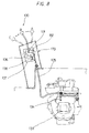
- Fig. 8 is a side view of a forward/rearward movement initiating unit 170, particularly showing the relationship between a forward/rearward movement lever 130 for the vibration compacting roller and a hydraulic pump operatively connected to each other to drivably running the vibration compacting roller.
- a vibration compacting roller driving system to instruct that the vibration compacting roller is caused to run with the aid of the forward/rearward movement initiating unit 170 by selectively displacing the forward/rearward movement lever 130 on an operator's seat to one of a forward movement position A, a neutral (stopped) position B and a rearward movement position C.
- the fundamental structure of the forward/rearward movement initiating unit 170 is such that an actuating arm 132 secured to a base shaft 131 is operatively associated with the forward/rearward movement lever 130, and a controlling lever 134 is operatively connected to the actuating arm 132 via a control cable 135 in order to change the direction of rotation of a variable capacity type hydraulic pump 133 to the opposite one for drivably running the vibration compacting roller, whereby a turning stroke of the actuating arm 132 is transmitted to the control lever 134.
- the variable capacity type hydraulic pump 133 is hydraulically connected to a vibration generating hydraulic motor (not shown) via a piping to vibratively drive the vibration rolling drum.
- a cam 136 is formed integral with the base shaft 131, and a neutral position detecting limit switch 138 serving as forward/rearward movement lever neutral position detecting means is disposed on the frame 137 having the forward/rearward movement lever 130 mounted thereon. As the cam 135 is turnably displaced, the neutral position detecting limit switch 138 detects whether or not the forward/rearward movement lever 130 is located at one of the forward movement position A, the rearward movement position C and the neutral position B.
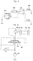
- An amplitude changing switch 253 serving as vibration mode setting means is disposed in a signal circuit shown in Fig. 9 so as to actuate a solenoid driven change valve 252 shown in Fig. 10 that is a hydraulic circuit diagram.
- a solenoid driven change valve 252 shown in Fig. 10 that is a hydraulic circuit diagram.
- the rotational driving force of the hydraulic motor 250 is transmitted to the vibration generating shaft 255 integrally connected to an output shaft of the hydraulic motor 250 in such a manner as to allow the vibration generating shaft 255 to be rotated in the same direction as that of the hydraulic motor 250.
- reference numeral 257 designates an automatic/manual changing switch.
- the neutral position detecting limit switch 138 serving as forward/rearward movement lever neutral position detecting means is hitherto actuated to the OFF side when the forward/rearward movement lever 130 is located at the position in the vicinity of the neutral position B between the forward movement position A and the rearward position C in order to enable the neutral position B of the forward/rearward movement lever 130 to be detected. Subsequently, the neutral position detecting limit switch 138 activates a vibration shaft rotation controlling unit 266. Specifically, a solenoid driven change valve 252 shown in Fig.
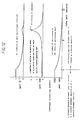
- FIG. 12 is a graph which shows by way of example how the relationship among the number of revolutions of the vibration generating shaft, a magnitude of deviation of the gravity center of each of the movable eccentric weights 257 and 257' away from the center axis of the vibration generating shaft 255, and an intensity of decelerated vibration varies for a period of time from the state that the vibration generating shaft 255 is steadily rotated till the state that the rotation of the vibration generating shaft 255 is stopped, as time elapses.
- the number of revolutions of the vibration generating shaft 255 is gradually reduced from the point of time when the forward/rearward movement lever 130 is displaced to the neutral position, and in the shown case, the operative state of the vibration compacting roller coincides with a resonance point after a period of five seconds elapses. Obviously, at this time, the magnitude of deviation of the center axis of the vibration rolling drum away from that of the vibration compacting roller, i.e., an amplitude of each vibration is increased.
- a number of small corrugated ruggednesses are formed on the compacted ground surface having the vibration rolling drum brought in contact therewith.
- the vibration rolling drum coincides with the resonance point in the course of shifting from the state that the number of revolution of the vibration generating shaft 255 is increased to that corresponding to the steady rotating state of the vibration generating shaft 255, resulting in the vibration rolling drum being likewise caused to resonate. Consequently, another drawback of the vibration rolling drum is such that a number of small corrugated ruggednesses are likewise formed on the compacted ground surface having the vibration rolling drum brought in contact therewith.
- the vibration compacting roller reciprocably moves on the road surface within a predetermined working range several times to perform a rolling operation with the vibration rolling drum while the forward/rearward movement lever is changeably displaced with an operator's hand.
- the rotation of the vibration generating shaft 255 is stopped every time the forward/rearward movement lever 130 is located at the neutral position (corresponding to the position where the rotation of the vibration rolling drum is stopped)
- This leads to the result that a large magnitude of load should be borne by the hydraulic pump and the vibration generating hydraulic motor every time the forward/rearward movement lever 130 is located at the neutral position, resulting in a large amount of energy loss arising.
- a large amount of time loss is caused not only when the vibration generating shaft 255 starts to be rotated but also when the rotation of the vibration generating shaft 255 is stopped.
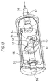
- a cylindrical casing 51 includes cantilever-like shafts 56 and 57 on the opposite sides to serve as bearings.
- the cylindrical casing 51 is supported by end plates of a vibration rolling drum (not shown).
- a movable eccentric weight 52 is turnably disposed in the cylindrical casing 51 to turn around a pivotal shaft 53 which extends through the center axis of the cylindrical casing 51 at a right angle relative to the latter. With this construction, a magnitude of eccentric moment induced by the eccentric weight 52 can be changed to another one by dislocating the eccentric weight 52 around the pivotal shaft 52 in the cylindrical casing 51 so as to enable a quantity of vibrative movement transmitted from the eccentric weight 52 to the vibration rolling drum to be adjusted as desired.
- the adjustment of the vibrative movement is achieved with the aid of an adjusting unit which is substantially composed of a plate 55 having a longitudinally extending slot 54 formed therethrough so as to enable the position of the slot 54 to be adjusted in the axial direction of the cylindrical casing 51.
- the right-hand end of the plate 55 is fixedly secured to an adjusting rod 58, while the left-hand end of the plate 55 is fixedly secured to an annular adjusting device 59.
- the pivotal shaft 53 for the eccentric weight 52 extends through the slot 54 of the plate 55, and the plate 55 can slidably be displaced in the longitudinal direction of the adjusting rod 58 without any hindrance caused due to the presence of the pivotal shaft 53.
- the eccentric weight 52 includes a driving rod 60 which extends through the slot 54 of the plate 55 in the transverse direction. As the plate 55 is axially displaced by the adjusting rod 58 in the leftward direction, the eccentric weight 52 is turnably displaced around the pivotal shaft 53 by the driving rod 60 while scribing a pivotal locus therewith, causing a magnitude of eccentric moment induced by the eccentric weight 52 to be changed as desired. Thus, an amplitude of vibrative movement induced by the eccentric weight 52 during rotation of the cylindrical casing 51 can be changed to another one corresponding to the deviation of the gravity center of the eccentric weight 52 from the center axis of the cylindrical casing 51.
- a hydraulic system and an eccentricity adjusting system for the vibrating mechanism can be designed with minimized dimensions, resulting in a danger of causing oil leakage from the hydraulic system being reduced or alleviated.
- an intensity of hydraulic pressure applied to the hydraulic system can reliably be set to a desired value.
- the prior invention does not disclose a measure to be taken for controlling an amplitude of each vibration.
- the conventional vibration rolling drum has a problem that a desired amplitude of each vibration can not simply be determined with the vibration rolling drum itself.
- the present invention has been made in consideration of the aforementioned background.
- An object of the present invention is to provide a vibrating mechanism employable for a variable amplitude type vibration compacting roller wherein the vibrating mechanism assures that a movable eccentric weight can simply be supported in a cylindrical casing, and essential components constituting the vibrating mechanism can easily be assembled in the cylindrical casing.
- Another object of the present invention is to provide an apparatus for generating vibrations for a vibration compacting roller with a variable amplitude wherein the apparatus assures that it is not necessary that the direction of rotation of a vibration generating shaft is changed to the opposite one every time a vibration mode is changeably selected, and a quantity of eccentricity of the vibration generating shaft can automatically be controlled to have an amplitude of each vibration corresponding to the selected vibration mode.
- Another object of the present invention is to provide an apparatus for generating vibrations for a vibration compacting roller with a variable amplitude wherein the apparatus assures that in the case that a forward/rearward movement lever is displaced from a forward movement position or a rearward movement position to a neutral position when e.g., an asphalt based pavement material is compacted by rolling, vibration of a vibration rolling drum can be stopped without any occurrence of resonance of the vibration rolling drum, in the case that the forward/rearward movement member is displaced from the neutral position to the forward movement position or the rearward movement position, vibrations can be generated without any occurrence of resonance of the vibration rolling drum, and moreover, when vibration of the vibration rolling drum is stopped, the compacted surface of the asphalt based pavement material is not largely lowered and any small corrugated ruggedness is not formed on the compacted surface of the asphalt based pavement material.
- Further object of the present invention is to provide an apparatus for generating vibrations for a vibration compacting roller with a variable amplitude wherein the apparatus assures that in the case that a running speed of the vibration compacting roller is lower than a predetermined running speed, vibration of the vibration compacting roller can be stopped without any occurrence of resonance of a vibration rolling drum, in the case that the running speed of the vibration compacting roller is higher than the predetermined running speed, vibrations can be generated without any occurrence of resonance of the vibration rolling drum, and when vibration of the vibration compacting roller is stopped, the compacted surface of a material to be compacted is not lowered, and moreover, any small corrugated ruggedness is not formed on the compacted surface of the foregoing material.
- Another object of the present invention is to provide a method of generating vibrations for a vibration compacting roller with a variable amplitude by operating an apparatus of the foregoing type.
- a vibrating mechanism which comprises a vibration generating shaft composed of a pair of supporting members disposed in the spaced relationship while facing to each other, a movable eccentric weight turnably supported between the pair of supporting members to turn in the direction orienting at a right angle relative to the center axis of the vibration generating shaft, and eccentric weight driving means for rotating the eccentric weight about a pivotal shaft transversely extending relative to the vibration generating shaft.
- the eccentric weight driving means serves to deviate the gravity center of the eccentric weight away from the center axis of the vibration generating shaft.
- the eccentric weight driving means is composed of an actuator, a shaft projecting outside of the actuator, a joint rotatably fitted to the shaft, and a connecting rod of which one end is operatively connected to the joint side and of which other end is operatively connected to the eccentric weight side.
- the connecting rod serves to transform the linear movement of the joint away from the actuator into the turning movement of the eccentric weight about the pivotal shaft transversely extending relative to the vibration generating shaft.
- the supporting members disposed in the spaced relationship while facing to each other to constitute the vibration generating shaft which turnably supports the eccentric weight in the direction orienting at a right angle relative to the pivotal shaft transversely extending relative to the center axis of the vibration generating shaft, and the eccentric weight driving means turnably displaces the eccentric weight about the pivotal shaft transversely extending relative to the center axis of the vibration generating shaft to deviate the gravity center of the eccentric weight away from the center axis of the vibration generating shaft.
- variable amplitude type vibration compacting roller which includes a vibrating mechanism constructed according to the first aspect of the present invention.
- an apparatus for generating vibrations for a vibration compacting roller with a variable amplitude including a vibrating mechanism adapted to change an amplitude of each vibration to another one by deviating the gravity of a movable eccentric weight in a vibration generating shaft away from the center axis of the vibration generating shaft, wherein the apparatus comprises eccentricity signal generating means for generating a signal for deviating the gravity center of the eccentric weight away from the center axis of the vibration generating shaft, vibration mode setting means capable of selectively setting an amplitude of each vibration, eccentric weight eccentricity quantity detecting means for detecting a quantity of eccentricity of the eccentric weight, eccentric weight eccentricity quantity controlling means for controlling a quantity of eccentricity of the eccentric weight with the aid of vibration mode setting means for setting a desired vibration mode as well as the eccentric weight eccentricity quantity detecting means in response to a signal transmitted from the eccentricity signal generating means.
- forward/rearward movement lever neutral position detecting means detects the neutral position, and subsequently, the eccentric weight eccentricity quantity controlling means locates the gravity center of the eccentric weight substantially on the axis line of the vibration generating shaft in response to a signal transmitted from the eccentricity signal generating means to instruct that the neutral position is detected, whereby an intensity of vibration generating force is reduced to a level of zero.
- the eccentric weight eccentricity quantity controlling means controls a quantity of eccentricity of the eccentric weight in such a manner as to generate vibrations each having an amplitude corresponding to that set by the vibration mode setting means.
- an apparatus for generating vibrations for a vibration compacting roller with a variable amplitude including a vibrating mechanism adapted to change an amplitude of each vibration to another one by deviating the gravity center of a movable eccentric weight in a vibration generating shaft away from the center axis of the vibration generating shaft, wherein the apparatus comprises forward/rearward movement lever neutral position detecting means for detecting a neutral position of a forward/ rearward lever, and vibration shaft eccentricity quantity controlling means for locating the gravity center of the eccentric weight substantially on the center axis of the vibration generating shaft in response to a signal transmitted from the forward/rearward movement lever neutral position detecting means to instruct that the neutral position is detected.
- the eccentric weight eccentricity quantity controlling means is constructed in such a manner that the gravity center of the eccentric weight is located substantially on the center axis of the vibration generating shaft in response to a signal transmitted from the forward/rearward movement lever neutral position detecting means to instruct that the neutral position is detected while the vibration generating shaft is steadily rotated without any stopping of rotation thereof.
- the forward/rearward movement lever neutral position detecting means detects the neutral position, and subsequently, the eccentric weight eccentricity quantity controlling means serves to locate the gravity center of the eccentric weight substantially on the center axis in response to a signal transmitted from the forward/rearward movement lever neutral detecting means to instruct that the neutral position is detected, causing no vibration to be generated by the vibration generating shaft. Thereafter, when the forward/ rearward movement lever is displaced from the neutral position to the forward movement position or the rearward movement position, the gravity center of the eccentric weight is deviated away from the center axis of the vibration generating shaft which in turn generate vibrations as it is rotated.
- an apparatus for generating vibrations for a vibration compacting roller with a variable amplitude including a vibrating mechanism adapted to change an amplitude of each vibration to another one by deviating the gravity center of a movable eccentric weight in a vibration generating shaft away from the center axis of the vibration generating shaft, wherein the apparatus comprises running speed detecting means for detecting a running speed of the vibration compacting roller, running speed setting means, running speed comparing means for comparing the running speed of the vibration compacting roller detected by the running speed detecting means with a running speed of the vibration compacting roller set by the running speed setting means by comparing a signal transmitted from the running speed detecting means with a signal transmitted from the running speed setting means, in order to whether or not the running speed of the vibration compacting roller detected by the running speed detecting means is higher than the running speed of the vibration compacting roller set by the running speed setting means, and eccentric weight eccentricity quantity controlling means for locating the gravity center of the eccentric
- the eccentricity signal generating means includes forward/ rearward movement lever neutral position detecting means for detecting whether or not a forward/rearward movement lever for instructing a command of forward movement, stoppage or rearward movement of the vibration compacting roller to a vibration compacting roller driving system is located at a neutral position, and when the forward/rearward movement lever is located at the position other than the neutral position, the eccentricity signal generating means generates an eccentricity signal.
- the eccentricity signal generating means includes running speed detecting means for detecting the present running speed of the vibration compacting roller in response to a signal transmitted from the vibration compacting roller driving system and running speed comparing means for comparing the running speed of the vibration compacting roller detected by the running speed detecting means with the running speed of the vibration compacting roller set by the running speed setting means, and when the running speed of the vibration compacting roller detected by the running speed detecting means is higher than the running speed of the same set by the running speed setting means, the eccentricity signal generating means generates an eccentricity signal.
- the eccentric weight eccentricity quantity controlling means includes an actuator for changing a quantity of eccentricity of the gravity center of the eccentric weight away from the center axis of the vibration generating shaft to another one by displacing the eccentric weight and solenoid driven change valves for controlling the movement of the actuator
- the eccentric weight eccentricity quantity detecting means includes a plurality of eccentricity quantity detecting sensors electrically connected to solenoid coils of the solenoid driven change valves via signal lines for activating the actuator in such a manner so as to increase a quantity of eccentricity of the eccentric weight.
- Each of the eccentricity quantity detecting sensors is activated when a movable portion of the actuator is displaced by a predetermined distance corresponding to a predetermined quantity of eccentricity.
- the eccentric weight eccentricity quantity controlling means serves to locate the gravity center of the eccentric weight substantially on the center axis of the vibration generating shaft without any stopping of rotation of the vibration generating means, when the running speed of the vibration compacting roller detected by the running speed detecting means is lower than the running speed of the vibration compacting roller set by the running speed setting means. Otherwise, in response to the foregoing signal, the eccentric weight eccentricity quantity controlling means may locate the gravity center of the eccentric weight substantially on the center axis of the vibration generating shaft while the latter is steadily rotated, when the running speed of the vibration compacting roller detected by the running speed detecting means is lower than the running speed of the vibration compacting roller set by the running speed setting means.
- a method of generating vibrations for a vibration compacting roller with a variable amplitude comprising a step of displacing a movable eccentric weight in a vibration generating shaft in such a manner that the gravity center of the eccentric weight is located substantially on the center axis of the vibration generating shaft so as to allow the vibration compacting roller to be held in the vibration stopped state in response to a detection signal derived from detecting of a running speed of the vibration compacting roller when the running speed of the vibration compacting roller is lower than a first predetermined running speed, and a step of displacing the eccentric weight in such a manner that the gravity center of the eccentric weight is deviated away from the center axis of the vibration compacting roller so as to allow the vibration compacting roller to be held in the vibration generating state in response to the foregoing signal when the running speed of the vibration compacting roller is higher than a second predetermined running speed.
- the gravity center of the eccentric weight is located substantially on the center axis of the vibration generating shaft, and when the running speed of the vibration compacting roller is higher than the second predetermined running speed, the eccentric weight is displaced in such a manner than the gravity center of the eccentric weight is deviated away from the center axis of the vibration generating shaft.
- the vibration generating apparatus includes a forward/rearward movement initiating unit 170 which is substantially composed of a forward/rearward movement lever 130 adapted to be displaced to one of a forward movement position A, a neutral (stopped) position B and a rearward movement position, a control lever 134 operatively associated with the forward/rearward movement lever 130 to change the direction of rotation of a variable capacity type hydraulic pump 133 to the opposite one and change the running speed of the vibration compacting roller for drivably running the vibration compacting roller to another one, and a neutral position detecting limit switch 138 serving as forward movement/rearward movement lever neutral position detecting means to detect with the aid of a cam 136 operatively associated with the forward/rearward movement lever 130 whether or not the
- an eccentricity signal generating unit is substantially composed of the forward/rearward movement lever 130 which serves to issue a command for forward movement or rearward movement of the vibration compacting roller to a vibration compacting roller driving system, and when the forward/rearward movement lever 130 is located at the position other than the neutral position, an eccentricity signal is generated by the eccentricity signal generating unit.
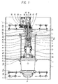
- Fig. 1 is a sectional plan view of the vibration generating apparatus for a vibration compacting roller constructed in accordance with the first embodiment of the present invention.
- a vibration rolling drum 1 includes mirror plates 2 and 2' in the spaced relationship as seen in the axial direction, and a cylindrical casing 3 for a vibrating mechanism 4 to be described later is fixedly secured to the mirror plates 2 and 2' on the opposite sides thereof.
- the vibrating mechanism 4 for generating vibrations for the vibration compacting roller with a variable amplitude is received in the cylindrical casing 1.
- a supporting member 13A is fitted to a left-hand frame 11 for the vibration compacting roller (not shown) via a plurality of vibration proofing members 12A, and a hydraulic motor 14 including a speed reducing unit for drivably running the vibration compacting roller is attached to the supporting member 13A. Since a rotational driving portion 14a of the hydraulic motor 14 is affixed to the mirror plate 2 of the vibration rolling drum 1, the vibration rolling drum 1 is caused to roll as the rotational driving portion 14 is rotated.
- a supporting member 13B is fitted to a right-hand frame 11' for the vibration compacting roller via a plurality of vibration proofing members 12B, and a rotatable wheel member 17 having a shaft hole 17a formed therein is rotatably supported in a bearing member 13B' of the supporting member 13B with a bearing 16 interposed therebetween.
- the rotatable wheel member 17 is affixed to the right-hand mirror plate 2.
- Two elongated plate-shaped supporting members 18 are arranged in the spaced relationship in the cylindrical casing 3 while facing to each other.
- a pivotal shaft 6 is bridged between both the supporting members 18, and a movable eccentric weight 6a is firmly fitted onto the pivotal shaft 6 in such a manner as not to be rotated about the latter.
- the left-hand ends of the supporting members 18 are affixed to a cover member 19, and a boss portion 20 of the cover member 19 is rotatably supported by a supporting member 21 located in the vicinity of the left-hand end of the cylindrical casing 3 with a bearing 22 interposed therebetween.
- a cylindrical guide case 10a is made integral with the right-hand ends of the plate members 18 for the purpose of guiding the slidable displacement of a joint 23 to be described later, and the right-hand end part of the guide case 10a is rotatably supported in the rotatable wheel member 17.
- the left-hand end part of a shaft 24 having a shaft hole 24a formed therein in the axial direction is spline-connected to the right-hand part of the guide case 10a, and a gear 25 is immovably fitted onto the shaft 24 at the position in the vicinity of the right-hand end of the shaft 24.
- a hydraulic cylinder 7 serving as an actuator is disposed at the position outside of the bearing portion 13B' of the right-hand supporting plate 13 with the aid of a supporting member 26 in such a manner that the center axis of the hydraulic cylinder 7 is positionally coincident with the center axis of the vibration rolling drum 1.
- a rod 7a projecting outside of the hydraulic cylinder 7 to serve as a thrusting shaft is inserted through the shaft hole 24a of the shaft 24, and the joint 23 is disposed on the left-hand end side of the rod 7a.
- the joint 23 is rotatably supported on the rod 7a side with the aid of a bearing 27.
- a vibration generating hydraulic motor 9 is arranged at the position deviated from the center axis of the vibration rolling drum 1 and located in the vicinity of the right-hand end of the bearing portion 13B' of the right-hand supporting plate 13, with the aid of a supporting member 28.
- a gear 29 is firmly fitted onto a driving shaft 9a of the hydraulic motor 9 to mesh with a gear 25 firmly fitted onto the shaft 24, whereby the driving force generated by the hydraulic motor 9 is transmitted to the shaft 24 via the gears 29 and 25. Consequently, to carry out the present invention, a vibration generating shaft 10 is constructed by a combination made among the shaft 24, the pair of supporting members 18 and the boss member 20.
- a variable amplitude type vibrating mechanism 4 is constructed by a combination made among the hydraulic cylinder 7, the rod 7a, the joint 23 and the connecting rod 8.
- the first embodiment of the present invention has been described with respect to the case that the hydraulic cylinder 7 is employed as an actuator.
- the present invention should not be limited only to the hydraulic cylinder 7.
- an electric motor, a solenoid and other hitherto known actuator may be substituted for the hydraulic cylinder 7.
- the vibrating mechanism is substantially composed of a vibration generating shaft including a pair of elongated plate-shaped supporting members disposed in the spaced relationship while facing to each other, a movable eccentric weight turnably supported to turn about a pivotal shaft transversely extending at a right angle relative to the center axis of the vibration generating shaft between both the supporting members, and an eccentric weight driving unit for deviating the gravity of the eccentric weight away from the center axis of the vibration generating shaft, and the vibration generating shaft is exposed to the outside with the exception of the supporting members disposed in the opposing relationship.
- the eccentric weight can simply be supported and easily assembled in the cylindrical casing.
- the vibration rolling drum integrated with the cylindrical casing is caused to slowly roll on the ground surface to be compacted therewith while the vibration shaft is received in the cylindrical casing and rotated at a high rotational speed, whereby lubricant falls down from the cylindrical casing in the interior of the vibration generating shaft to reach locations to be lubricated with the lubricant.
- these locations can reliably be lubricated with the lubricant.
- the eccentric weight can exactly be located in the cylindrical casing.
- the vibration generating shaft has an opened structure as mentioned above, a magnitude of inertia moment generated by the eccentric weight can be reduced, a long time is not taken until the rotation of the vibration generating shaft is stopped, and moreover, an amount of energy loss can be reduced.
- the first embodiment of the present invention has been described above with respect to the case that the vibrating mechanism is applied to a vibration compacting roller.
- the present invention should not be limited only to this embodiment.
- the present invention can equally be applied to a vibration utilizing machine such as a vibration type soil compacting machine, a vibration type pile driving machine or a similar machine.
- the rod 7a of the hydraulic cylinder 7 is expanded as shown in Fig. 2(a) until the gravity center of the eccentric weight 6a positionally coincides with the center axis of the vibration generating shaft 10, causing the eccentric weight 6a to exhibit an upright standing attitude.
- the dead weight of the eccentric weight 6a is distributed uniformly on the opposite sides relative to the center axis of the vibration generating shaft 10.
- the rod 7a of the hydraulic cylinder 7 is retractively contracted so that the eccentric weight 6a is displaced to the one side away from the center axis of the vibration generating shaft 6a as shown in Fig. 2(b), causing the eccentric weight 6a to be turned about the pivotal shaft 6, whereby the gravity center of the eccentric weight 6a is deviated away from the center axis of the vibration generating shaft 10.
- the gravity center of the eccentric weight 6a is deviated away from the center axis of the vibration generating weight 10 to a small extent, resulting in the operative state represented by a low amplitude (L) being selectively taken.
- the changing of the operative state from the high vibration amplitude state to the low vibration amplitude state, and vice versa is executed by a vibration amplitude changing switch 43 for actuating a variable amplitude controlling unit 40 shown in Fig. 3 and Fig. 4.
- the variable amplitude controlling unit 40 is substantially composed of a hydraulic pump 47, a hydraulic cylinder 7 arranged along the center axis of the vibration generating shaft 10, a joint 23 rotatably disposed in a main body of the hydraulic cylinder 7 to rotate about the center axis of a rod 7a, a connecting rod 23 of which one end is operatively connected to the joint 23 side and of which other side is operatively connected to the eccentric weight 6a side, and a solenoid driven change valve 44 disposed in a hydraulic circuit to supply pressurized hydraulic oil from a hydraulic pump 47 to the hydraulic cylinder 7.
- a solenoid driven change valve 42 operatively associated with the vibration amplitude changing switch 43 serving as vibration mode setting means for activating the solenoid driven change valve 42 is disposed in the form of a solenoid valve in a hydraulic oil supplying circuit hydraulically connected to the hydraulic pump 41 for supplying pressurized hydraulic oil to a vibration generating hydraulic motor 9.
- the vibration amplitude changing switch 43 is set to the state represented by a low amplitude (L) or a high amplitude (H)
- a signal is normally fed to a solenoid coil SOL1 of the solenoid driven change valve 42 designed in the form of a solenoid valve in order to rotate the vibration generating hydraulic motor 9.
- the vibration generating hydraulic motor 9 is rotated, the vibration generating shaft 10 is rotated in a predetermined direction.
- another solenoid driven change valve 44 is disposed in the hydraulic circuit for supplying pressurized hydraulic oil from the hydraulic pump 47 to the hydraulic cylinder 7.
- a neutral position (N) of the forward/rearward movement lever 130 is detected by a neutral position detecting switch 38, electric current is fed to a solenoid coil SOL2 of the solenoid driven change valve 44 so as to allow the rod 7a of the hydraulic cylinder 7 to be expanded. Consequently, the eccentric weight 6a is held in the upright standing state as shown in Fig. 2(a) so that the gravity center of the eccentric weight 6a is located on the center axis of the vibration generating shaft 10.
- a L position sensor 45 disposed at the substantially intermediate position of the main body of the hydraulic cylinder 7 to serve as an eccentricity quantity detecting sensor operatively associated with the eccentric weight eccentricity quantity detecting unit allows the rod 7a of the hydraulic cylinder 7 to be retractively contracted to a predetermined intermediate position so that the feeding of electric current to the solenoid coil SOL3 of the solenoid driven change valve 44 is interrupted.
- the solenoid driven change valve 44 is displaced to the neutral position so that the supplying of pressurized hydraulic oil to the hydraulic cylinder 7 is stopped, and at the same time, the retractive contracting operation of the hydraulic cylinder 7 is stopped. Consequently, the eccentric weight 6a is held in the operative state represented by phantom lines in Fig. 2(b). At this time, since the gravity center of the eccentric weight 6a is deviated away from the center axis of the vibration generating shaft 10 to a small extent, an amplitude of each vibration generated by the vibration generating shaft 10 is suppressively reduced.
- a H position sensor 46 likewise serving as an eccentricity detecting sensor stops the feeding of electric current to the solenoid coil SOL3 of the solenoid driven change valve 44. Subsequently, the solenoid driven change valve 44 is displaced to the neutral position so that the supplying of pressurized hydraulic oil to the hydraulic cylinder 7 is stopped, and the retractive contracting operation of the rod 7a of the hydraulic cylinder 7 is stopped. Consequently, while the operative state of the eccentric weight 6a largely deviated from the center axis of the vibration generating shaft 120 as represented by solid lines in Fig.
- reference numeral 39 designates an automatic/manual changing switch adapted to be actuated to one of the automatic side and the manual side.
- two position sensors 45 and 46 each designed in the form of lead switch adapted to be magnetically actuated to serve as eccentric weight eccentricity quantity detecting means are disposed at two locations on the main body of the hydraulic cylinder 7. Normally, each lead switch is turned on but when a magnetic ring disposed in the vicinity of the rod 7a of the hydraulic cylinder 7 comes near to the lead switch, the latter is turned off. This enables the extent of expansion of the rod 7a of the hydraulic cylinder 7 to be detected.
- the eccentric weight eccentricity detecting unit includes a plurality of eccentric weight eccentricity quantity detecting sensors each adapted to be activated when a movable portion (rod 7a) of the hydraulic cylinder 7 is displaced to a predetermined position while they are electrically connected to the solenoid coil SOL3 of the solenoid driven change valve 44 disposed on the side where the hydraulic cylinder 7 is actuated in such a manner as to increase a quantity of eccentricity of the vibration generating shaft 10.
- the foregoing embodiment has been described above with respect to the case that two eccentric weight eccentricity quantity detecting sensors are disposed on the main body of the hydraulic cylinder to detect vibrations each having a high amplitude or a low amplitude.
- the neutral position detecting limit switch 38 sends to the solenoid coil SOL2 of the solenoid driven change valve 44 a signal instructing that the forward/ rearward movement lever 130 is located at the neutral position B, whereby the rod 7a of the hydraulic cylinder 7 is expanded so as to allow the gravity center of the eccentric weight 6a to be located on the center axis of the vibration generating shaft 10, resulting in an intensity of vibration generating force being reduced to a level of zero.
- the neutral position detecting limit witch 138 does not feed an electric current to the solenoid coil SOL2 of the solenoid driven change valve 44 but feeds an electric current the solenoid coil SOL3 of the solenoid driven change valve 44, whereby the gravity center of the eccentric weight 6a is largely deviated away from the center axis of the vibration generating shaft 10. While the foregoing state is maintained, the vibration generating shaft 10 is rotated so as to allow the vibration generating apparatus to generate vibrations each having a high amplitude.
- the neutral position detecting limit switch 38 feeds electric current to the solenoid coil SOL2 of the solenoid driven change valve 44 but not to the solenoid coil SOL3 of the same, whereby the rod 7a of the hydraulic cylinder 7 is expanded until the gravity center of the eccentric weight 6a is located on the center axis of the vibration generating shaft 10.
- the vibration generating shaft 10 is continuously rotated while an amplitude of each vibration is reduced to a level of zero.
- the vibration rolling drum 1 is rotated with a high amplitude in the same manner as when the forward/rearward movement lever 130 is displaced to the forward movement position A.
- the vibration amplitude hanging switch 43 is changeably actuated from the operative state represented by a high amplitude (H) to the operative state represented by a low amplitude (L) in the course of each road surface compacting operation, the forward/rearward movement lever 130 is once restored to the neutral position B, and thereafter, the vibration amplitude changing switch 43 is changeably actuated to the opposite side.
- the neutral position detecting limit switch 138 does not feed electric current to the solenoid coil SOL2 of the solenoid driven change valve 44 but it feeds electric current to the solenoid coil SOL3 of the same, whereby the gravity center of the eccentric weight 6a is deviated away from the center axis of the vibration generating shaft 10 to a small extent, resulting in the vibration generating apparatus generating vibrations each having a low amplitude.
- the vibration generating apparatus since the vibration generating apparatus includes as essential components an eccentricity signal generating unit for generating a signal for deviating the gravity center of the eccentric weight away from the center axis of the vibration generating shaft, an eccentric weight eccentricity quantity detecting unit for detecting a quantity of eccentricity of the eccentric weight, and an eccentric weight eccentricity quantity controlling unit for controlling a quantity of eccentricity of the vibration generating shaft with the aid of a vibration mode setting unit for setting an applicable vibration mode and the eccentric weight eccentricity quantity detecting unit in response to a signal transmitted from the eccentricity signal generating unit.
- a vibration mode setting unit for setting an applicable vibration mode and the eccentric weight eccentricity quantity detecting unit in response to a signal transmitted from the eccentricity signal generating unit.
- a desired amplitude of each vibration can simply be determined in contrast with the conventional vibration generating apparatus adapted to change an amplitude of each vibration to another one without any changing of the direction of rotation of the vibration generating shaft to the opposite side.
- the rod 7a of the hydraulic cylinder 7 held in the retractive contracted state is once expanded to locate the gravity center of the eccentric weight 6a on the center axis of the vibration generating shaft 10, and subsequently, after the forward/rearward movement lever 130 is displaced to the forward movement position A or the rearward movement position C, the rod 7a of the hydraulic cylinder 7 is retractively contracted so as to allow the center axis of the eccentric weight 6a to be deviated away from the center axis of the vibration generating shaft 10 to thereby generate vibrations with the aid of the eccentric weight 6a and the vibration generating shaft 10.
- the range of detecting the neutral position B on the cam 136 is widened or a hitherto known adequate sequence controlling unit is arranged in a controller(not shown) for the vibration generating apparatus to properly control the running state of the vibration compacting roller in the forward/rearward movement and the expansion or contraction of the rod 7a of the hydraulic cylinder 7 in order to assure that the vibration compacting roller can more correctly run without an occurrence of resonance.
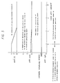
- Fig. 5 is a graph which illustrates how the relationship among the number of revolutions of the vibration generating shaft 10, a magnitude of deviation of the gravity center of the eccentric weight 6a away from the center axis of the vibration generating shaft 10 and an intensity of each decelerated vibration varies when the forward/rearward movement lever 130 is displaced from the forward movement position A or the rearward movement position B to the neutral position C while the vibration generating shaft 10 is steadily rotated.
- Fig. 5 diagrammatically illustrates by way of example the ideal case that the gravity center of the eccentric weight 6a completely coincides with the center axis of the vibration generating shaft 10 when the forward/rearward movement lever 130 is located at the neutral position B.
- the vibration generating apparatus exhibits the same pattern as mentioned above in such a manner that a magnitude of deviation of the gravity center of the eccentric weight 6a away from the center axis of the vibration generating shaft 10 and an intensity of decelerated vibration are increasingly reduced toward a level of zero without an occurrence of resonance.
- the vibration rolling drum 1 is continuously vibrated with a small amplitude for a period of several seconds.
- the vibration of the vibration rolling drum 1 with a small amplitude in that way has few effect on lowering of the compacted road surface or the like. Consequently, while the foregoing state is maintained, the vibrating compacting roller is brought in the vibration stopped state. In other words, as long as the gravity center of the eccentric weight 6a is located substantially on the center axis of the vibration generating shaft 10, it is assumed that the vibration compacting roller is held in the vibration stopped state.
- the gravity center of the eccentric weight 6a is located substantially on the center axis of the vibration generating shaft 10.
- the vibration generating shaft 10 is steadily rotated while the forward/rearward movement lever 130 is locates at the neutral position.
- the vibration of the vibration rolling drum 1 can reliably be stopped without any occurrence of resonance by locating the gravity center of the eccentric weight substantially on the center axis of the vibration generating shaft 10 in response to a signal transmitted from forward/rearward movement lever neutral position detecting unit 170 to instruct that the forward/rearward movement lever 130 is located at the neutral position B, before the number of revolutions of the vibration rolling drum 1 coincides with the foregoing resonance point.
- the vibration rolling drum 1 can start to be vibratively rotated without any occurrence of resonance from the inoperative state that the vibration rolling drum 1 is held in the vibration stopped state, as soon as the vibration compacting roller starts to run, provided that the vibration generating shaft 10 is continuously rotated in the steady state.
- the vibration rolling drum 1 can start to be vibratively rotated without any occurrence of resonance, provided that the gravity center of the eccentric weight 6a is located substantially on the center axis of the vibration generating shaft 10 when the number of revolutions of the vibration rolling drum 1 coincides with the foregoing resonance point.
- the vibration generating apparatus can be operated more reliably.
- the number of revolutions of the vibration generating shaft 10 is usually smaller than the number of revolutions of the vibration generating shaft 10 in the steady operative state of the latter. For this reason, it is recommendable that a measure is taken such that in response to a signal transmitted from the forward/rearward movement lever neutral position detecting unit 170 to instruct that the forward/rearward movement lever 130 is located at the neutral position B, the number of revolutions of the vibration generating shaft 10 is maintained at a value corresponding to the number of revolutions of the vibration generating shaft 10 in the steady rotating state or a value in excess of a predetermined value (i.e., a value larger than the number of revolution of the vibration generating shaft 10 approximately corresponding to the resonance point).
- a measure is taken such that in response to a signal transmitted from the forward/rearward movement lever neutral position detecting unit 170 to instruct that the forward/rearward movement lever 130 is located at the neutral position B, the number of revolutions of the vibration generating shaft 10 is maintained at a value corresponding to the number of revolution
- the vibration generating apparatus can advantageously be operated for the vibration compacting roller without any occurrence of resonance.
- a vibration generating apparatus constructed in accordance with a second embodiment of the present invention will be described below with reference to Fig. 4 and Fig. 6.
- a vibrating mechanism used for the vibration generating apparatus is constructed in the same manner as the preceding embodiment, repeated description on the structure of the vibrating mechanism is herein omitted for the purpose of simplification.
- the structure of the vibration generating apparatus constructed in accordance with the second embodiment of the present invention is substantially same to that shown in four drawings, i.e., Fig. 1 which shows the structure of the vibrating mechanism for a variable amplitude type vibration compacting roller, Fig. 2 which shows the operative state of an eccentric weight in the vibration generating apparatus, Fig.
- Fig. 9 which shows hydraulic circuits for the vibration generating apparatus
- Fig. 8 which shows a forward/rearward movement lever and a hydraulic pump arranged for drivably running the vibration compacting roller.
- the neutral position detecting limit switch 138 shown in Fig. 8 is not required.
- the vibration generating apparatus can more simply be constructed in accordance with the second embodiment of the present invention in contrast with the conventional vibration generating apparatus.
- the structure of the vibration generating apparatus constructed in accordance with the second embodiment of the present invention will be described hereinafter mainly with respect to components other than those shown in Fig. 1, Fig. 2, Fig. 4 and Fig. 8.
- Fig. 6 is a signal circuit diagram which is used for the vibration generating apparatus constructed in accordance with the second embodiment of the present invention.
- This signal circuit diagram shows that a member 81 such as a gear or the like disposed in a vibration compacting roller driving system, a running speed sensor 82 disposed in the vicinity of the member 81 in the form of a proximity sensor or the like to serve as running speed detecting means, a running speed calculating circuit 83, a running speed setting circuit 84 to serve as running speed setting means, and a running speed comparing circuit 85 to serve as running speed comparing means are arranged for the vibration generating apparatus.
- a member 81 such as a gear or the like disposed in a vibration compacting roller driving system
- a running speed sensor 82 disposed in the vicinity of the member 81 in the form of a proximity sensor or the like to serve as running speed detecting means
- a running speed calculating circuit 83 a running speed setting circuit 84 to serve as running speed setting means
- the running speed comparing circuit 85 comparatively determines a difference between the present running speed of the vibration compacting roller and a predetermined running speed of the same preset by the running speed setting circuit 84. In other words, it is comparatively determined by the running speed comparing circuit 85 whether or not the present running speed of the vibration compacting roller is higher than the foregoing predetermined running speed.
- an eccentric weight eccentricity quantity determining controlling unit 40 is activated for the vibration generating apparatus.
- the running speed of the vibration compacting roller compared in the running speed comparing circuit 85 is usually represented by an absolute value.
- the gravity center of the eccentric weight 6a is located on the center axis of the vibration generating shaft 10.
- the gravity center of the eccentric weight 6a is located substantially on the center axis of the vibration generating shaft 10.
- the eccentricity signal generating unit includes a running speed setting circuit 82 for previously setting a running speed of the vibration compacting roller in operative association with the vibration compacting roller driving system, a running speed comparing circuit 85, and a running speed comparing circuit 85 for comparing the running speed of the vibration compacting roller detected by the running speed detecting sensor 82 with the running speed of the same preset by the running speed setting circuit 84, and when the running speed of the vibration compacting roller detected by the running speed detecting sensor 82 is higher than the running speed of the same preset by the running speed setting circuit 84, an eccentricity signal is generated from the eccentricity signal generating unit.
- a vibration amplitude changing switch 43 when the rod 7a of the hydraulic cylinder 7 is displaced to the position corresponding to a predetermined low amplitude while a vibration amplitude changing switch 43 is actuated to selectively assume the operative state represented by a low amplitude (L), a L position sensor 45, i.e., an eccentricity quantity detecting sensor disposed at the substantially intermediate position on the main body of the hydraulic cylinder 7 to serve as eccentric weight eccentricity detecting means stops to feed electric current to the solenoid coil SOL3 of the solenoid driven change valve 44.
- L low amplitude
- the solenoid driven change valve 44 is actuated so as to allow the position of the rod 7a of the hydraulic cylinder 7 to be changed to an intermediate position, whereby the supplying of pressurized hydraulic oil to the hydraulic cylinder 7 is stopped and the retractive contracting operation of the hydraulic cylinder 7 is interrupted at the foregoing intermediate position. Consequently, while the gravity center of the eccentric weight 6a is deviated away from the center axis of the vibration generating shaft 10 to a comparatively small extent as shown in Fig. 2(b), the vibration generating shaft 10 is rotated to generate vibrations each having a low amplitude.
- the vibration compacting roller starts to run in the forward direction while the vibration amplitude changing witch 43 is actuated to assume the operative state represented by a high amplitude (H).
- the relay 86 is activated to stop the feeding of electric current to the solenoid coil SOL2 of the solenoid driven change valve 44 but feeds electric current to the solenoid coil SOL3 of the same, whereby the gravity center of the eccentric weight 6a is largely deviated away from the center axis of the vibration generating shaft 10.
- the vibration generating shaft 10 is rotated so as to allow the vibration generating apparatus to generate vibrations each having a high amplitude.
- the vibration of the vibration rolling drum can not be stopped unless the running speed of the vibration compacting roller is reduced to a level lower than the preset one, e.g., even though the forward/rearward movement lever 130 is quickly displaced from the forward movement position A to the rearward movement position C.
- the relay 86 When the running speed of the vibration compacting roller becomes lower than the preset one in the course of shifting from the forward movement to the rearward movement, the relay 86 is activated to stop the feeding of electric current to the solenoid coil SOL3 of the solenoid driven change valve 44 but feeds electric current to the solenoid coil SOL2 of the same, whereby the rod 7a of the hydraulic cylinder 7 is expended, causing the gravity center of the eccentric weight 6a to be located on the center axis of the vibration generating shaft 10 again. Consequently, an amplitude of each vibration is reduced to a level of zero, although the vibration generating shaft 10 is continuously rotated.
- the vibration rolling drum is vibrated with a high amplitude in the same manner as the case the vibration compacting roller runs in the forward direction.
- each changeable actuating operation of the vibration amplitude changing switch 43 is achieved while the vibration compacting roller is held in the vibration stopped state.
- the relay 86 is activated to stop the feeding of electric current to the solenoid coil SOL2 of the solenoid driven change valve 44 but feeds electric current to the solenoid coil SOL3 of the same, whereby the gravity center of the eccentric weight 6a is deviated away from the center axis of the vibration generating shaft 10 to a comparatively small extent, causing the vibration generating apparatus to generate vibrations each having a low amplitude.
- the vibration generating apparatus includes an eccentricity signal generating unit for generating a signal effective for deviating the gravity center of the eccentric weight away from the axis center of the vibration generating shaft, a vibration mode setting unit capable of selectively setting an applicable amplitude of each vibration, an eccentric weight eccentricity quantity detecting unit for detecting a quantity of eccentricity of the gravity center of the eccentric weight away from the center axis of the vibration generating shaft, and an eccentric weight eccentricity quantity controlling unit for controlling a quantity of eccentricity of the gravity center of the eccentric weight away from the center shaft of the vibration generating shaft with the aid of the vibration mode setting unit for selectively setting an applicable vibration mode and the eccentric weight eccentricity quantity detecting unit in response to a signal transmitted from the eccentricity signal generating unit.
- a quantity of eccentricity of the eccentric weight can automatically be controlled in such a manner as to selectively determine an applicable amplitude of each vibration corresponding to the selected vibration mode, a desired amplitude of each vibration can simply be set in contrast with the conventional vibration compacting roller wherein an amplitude of each vibration is changed to another one without any changing of the direction of rotation of the vibration generating shaft as shown in Fig. 13.
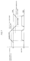
- Fig. 7 is a graph which illustrates how the relationship between a running speed of the vibration compacting roller and an amplitude (high amplitude or low amplitude) of each vibration generated by the vibration generating apparatus constructed in accordance with this embodiment varies as time elapses under a condition that the vibration compacting roller moves in the forward/rearward direction while the vibration generating shaft disposed in the vibration generating apparatus is steadily rotated.
- the vibration generating apparatus exhibits properties which assure that vibrations can stably be generated without any occurrence of resonance of the vibration rolling drum not only during running of the vibration compacting roller in the forward direction but also during running of the same in the rearward direction.
- an amplitude of each vibration is reduced to a level of zero as mentioned above.
- the running speed of the vibration compacting roller is lower than a first predetermined running speed while the vibration compacting roller runs in the forward direction, an amplitude of each vibration generated by the vibration generating apparatus is held still in the zero level state.
- a quantity of eccentricity of the gravity center of the eccentric weight away from the center axis of the vibration generating shaft is increased from the zero level to a preset value of amplitude.
- the running speed of the vibration compacting roller is gradually reduced, and when it is reduced in excess of a second predetermined running speed of the vibration compacting roller, a value of amplitude is reduced to a level of zero again.
- the running speed of the vibration compacting roller in the forward direction (represented by an absolute value) is held at the value corresponding to a second predetermined running speed of the vibration compacting roller after the running of the vibration compacting roller in the forward direction is reversely changed to the running of the same in the rearward direction
- an amplitude of each vibration generated by the vibration generating apparatus (represented by an absolute value) is held still in the zero level state in the same manner as the case that the vibration compacting roller runs in the forward direction.
- the running speed of the vibration compacting roller in the rearward direction exceeds the second predetermined speed of the same, a quantity of eccentricity of the gravity center of the eccentric weight away from the center axis of the vibration generating shaft is increased from the zero level to the foregoing preset value of amplitude.
- the running state of the vibration compacting roller in the rearward direction is reversely changed to the running state of the same in the forward direction via the neutral state, the aforementioned running relationship is repeated with the vibration generating apparatus.
- the first predetermined speed of the vibration compacting roller and the second predetermined speed of the same may be identical to each other. Otherwise, they may be different from each other.
- the vibration generating shaft As long as the vibration generating shaft is steadily rotated when the vibration compacting roller starts to run from the stopped state of running thereof in the forward direction or in the rearward direction, any resonance does not occur with the vibration rolling drum.
- the vibration rolling drum starts to be vibrated from the stopped state of vibration.
- the vibration generating shaft can start to be vibrated without any occurrence of resonance, provided that the gravity center of the eccentric weight is located substantially on the center axis of the vibration shaft when the number of revolutions of the vibration generating shaft coincides with the resonance point.
- the vibration rolling drum 1 can advantageously be vibrated without any occurrence of resonance.
Landscapes
- Engineering & Computer Science (AREA)
- Mechanical Engineering (AREA)
- Architecture (AREA)
- Civil Engineering (AREA)
- Structural Engineering (AREA)
- Road Paving Machines (AREA)
- Apparatuses For Generation Of Mechanical Vibrations (AREA)
Applications Claiming Priority (9)
| Application Number | Priority Date | Filing Date | Title |
|---|---|---|---|
| JP30008793 | 1993-11-30 | ||
| JP30008893 | 1993-11-30 | ||
| JP30008793A JP2727050B2 (ja) | 1993-11-30 | 1993-11-30 | 可変振幅振動ローラの起振装置 |
| JP30008893 | 1993-11-30 | ||
| JP5317845A JP2821847B2 (ja) | 1993-12-17 | 1993-12-17 | 振動機構 |
| JP31784593 | 1993-12-17 | ||
| JP33766593A JP2733733B2 (ja) | 1993-12-28 | 1993-12-28 | 振動ローラの起振方法およびその装置 |
| JP33766593 | 1993-12-28 | ||
| EP94118609A EP0655532B1 (fr) | 1993-11-30 | 1994-11-25 | Mécanisme de vibration et dispositif pour engendrer des vibrations dans un rouleau compresseur vibrant à amplitude variable |
Related Parent Applications (1)
| Application Number | Title | Priority Date | Filing Date |
|---|---|---|---|
| EP94118609A Division EP0655532B1 (fr) | 1993-11-30 | 1994-11-25 | Mécanisme de vibration et dispositif pour engendrer des vibrations dans un rouleau compresseur vibrant à amplitude variable |
Publications (3)
| Publication Number | Publication Date |
|---|---|
| EP0987372A2 true EP0987372A2 (fr) | 2000-03-22 |
| EP0987372A3 EP0987372A3 (fr) | 2000-06-07 |
| EP0987372B1 EP0987372B1 (fr) | 2003-05-07 |
Family
ID=27479766
Family Applications (3)
| Application Number | Title | Priority Date | Filing Date |
|---|---|---|---|
| EP99124002A Expired - Lifetime EP0987372B1 (fr) | 1993-11-30 | 1994-11-25 | Procédé et dispositif pour engendrer des vibrations dans un rouleau compresseur vibrant à amplitude variable |
| EP99123996A Expired - Lifetime EP0987371B1 (fr) | 1993-11-30 | 1994-11-25 | Dispositif pour engendrer des vibrations dans un rouleau compresseur vibrant à amplitude variable |
| EP94118609A Expired - Lifetime EP0655532B1 (fr) | 1993-11-30 | 1994-11-25 | Mécanisme de vibration et dispositif pour engendrer des vibrations dans un rouleau compresseur vibrant à amplitude variable |
Family Applications After (2)
| Application Number | Title | Priority Date | Filing Date |
|---|---|---|---|
| EP99123996A Expired - Lifetime EP0987371B1 (fr) | 1993-11-30 | 1994-11-25 | Dispositif pour engendrer des vibrations dans un rouleau compresseur vibrant à amplitude variable |
| EP94118609A Expired - Lifetime EP0655532B1 (fr) | 1993-11-30 | 1994-11-25 | Mécanisme de vibration et dispositif pour engendrer des vibrations dans un rouleau compresseur vibrant à amplitude variable |
Country Status (5)
| Country | Link |
|---|---|
| US (1) | US5618133A (fr) |
| EP (3) | EP0987372B1 (fr) |
| KR (1) | KR100329840B1 (fr) |
| AU (1) | AU692479B2 (fr) |
| DE (3) | DE69432913T2 (fr) |
Cited By (1)
| Publication number | Priority date | Publication date | Assignee | Title |
|---|---|---|---|---|
| DE102018113352A1 (de) * | 2018-06-05 | 2019-12-05 | Mts Maschinentechnik Schrode Ag | Anbauverdichter |
Families Citing this family (40)
| Publication number | Priority date | Publication date | Assignee | Title |
|---|---|---|---|---|
| JP2799691B2 (ja) * | 1995-07-19 | 1998-09-21 | 酒井重工業株式会社 | 振動タイヤローラ |
| US5781874A (en) * | 1995-11-28 | 1998-07-14 | Ingersoll-Rand Company | Control system for a compaction roller vibratory mechanism |
| JP3146411B2 (ja) * | 1996-12-12 | 2001-03-19 | 酒井重工業株式会社 | 振動機構およびその振動機構を用いた振動ローラ |
| US6109111A (en) * | 1997-02-14 | 2000-08-29 | Racine Federated Inc. | Concrete vibrator monitor |
| US5992238A (en) * | 1997-02-14 | 1999-11-30 | Racine Federated Inc. | Vibration speed sensor |
| US6125530A (en) | 1999-01-05 | 2000-10-03 | Lucent Technologies, Inc. | Method and apparatus for handling laser bar |
| SE513571C2 (sv) | 1999-03-18 | 2000-10-02 | Ulf Bertil Andersson | Anordning för alstring av mekaniska vibrationer |
| DE19913077C2 (de) * | 1999-03-23 | 2003-06-12 | Wacker Construction Equipment | Innenrüttler mit Meßsystem |
| US6224293B1 (en) | 1999-04-19 | 2001-05-01 | Compaction America, Inc. | Variable amplitude vibration generator for compaction machine |
| WO2002014609A1 (fr) * | 2000-08-18 | 2002-02-21 | Ingersoll-Rand Company | Appareil destine a commander le moyen vibratoire d'un vibrocompacteur |
| US7059802B1 (en) | 2000-11-15 | 2006-06-13 | Wacker Corporation | Vibratory compactor and compact exciter assembly usable therewith |
| DE10115260C2 (de) * | 2001-03-28 | 2003-04-30 | Bauer Maschinen Gmbh | Baumaschine zur Erzeugung von Schwingungen |
| DE10121383C2 (de) * | 2001-05-02 | 2003-04-03 | Wacker Werke Kg | Steuerung für eine Unwucht-Verstelleinrichtung in einem Vibrationserreger einer Bodenverdichtungsvorrichtung |
| US6981558B2 (en) | 2001-05-02 | 2006-01-03 | Wacker Construction Equipment Ag | Controller for an unbalanced mass adjusting unit of a soil compacting device |
| US6808741B1 (en) * | 2001-10-26 | 2004-10-26 | Seagate Technology Llc | In-line, pass-by method for vapor lubrication |
| US6637280B2 (en) * | 2001-10-31 | 2003-10-28 | Caterpillar Paving Products Inc | Variable vibratory mechanism |
| DE10210049B4 (de) * | 2002-03-07 | 2004-03-25 | Abg Allgemeine Baumaschinen-Gesellschaft Mbh | Verdichtungswalze |
| US7089823B2 (en) | 2002-05-29 | 2006-08-15 | Caterpillar Paving Products Inc. | Vibratory mechanism controller |
| SE525020C2 (sv) | 2003-03-21 | 2004-11-09 | Metso Dynapac Ab | Ställdon för reglering av en vältvals excenteraxels excentermoment |
| DE10333555B4 (de) * | 2003-07-23 | 2008-03-27 | Wacker Construction Equipment Ag | Innenrüttelvorrichtung mit Befreiungseinrichtung |
| US7938595B2 (en) * | 2007-04-30 | 2011-05-10 | Caterpillar Paving Products Inc. | Surface compactor and method of operating a surface compactor |
| EP2067533B2 (fr) * | 2007-12-06 | 2016-12-07 | ABI Anlagentechnik-Baumaschinen-Industriebedarf Maschinenfabrik und Vertriebsgesellschaft mbH | Vibrateur pour un appareil de fonçage vibratoire |
| CN101302736B (zh) * | 2008-07-07 | 2012-10-10 | 合肥永安绿地工程机械有限公司 | 振动压路机的振动轮 |
| US20110158745A1 (en) * | 2009-12-31 | 2011-06-30 | Caterpillar Paving Products Inc. | Vibratory system for a compactor |
| US8439598B2 (en) * | 2010-12-15 | 2013-05-14 | Caterpillar Inc. | Oscillatory compaction method |
| US8965638B2 (en) | 2011-06-30 | 2015-02-24 | Caterpillar Paving Products, Inc. | Vibratory frequency selection system |
| US8393826B1 (en) * | 2011-08-31 | 2013-03-12 | Caterpillar Inc. | Apparatus for transferring linear loads |
| WO2016089353A1 (fr) * | 2014-12-01 | 2016-06-09 | Volvo Construction Equipment Ab | Dispositif excentrique infiniment variable pour compacteur vibrant |
| CN104634650A (zh) * | 2014-12-06 | 2015-05-20 | 武汉科技大学 | 一种带磁力对中功能的路基动力响应试验用激振装置 |
| US10487461B2 (en) * | 2016-04-21 | 2019-11-26 | Volvo Construction Equipment Ab | Eccentric assembly for oscillating a compacting drum of a compacting machine |
| CN108166354A (zh) * | 2017-12-29 | 2018-06-15 | 郑州国知网络技术有限公司 | 一种市政施工用压路机的刮泥装置 |
| CN110130190B (zh) * | 2019-05-31 | 2021-01-05 | 李宝宁 | 一种道路施工用泥土夯实装置 |
| CN110695329A (zh) * | 2019-11-13 | 2020-01-17 | 中达连铸技术国家工程研究中心有限责任公司 | 一种具有内置偏心旋转机构的连铸振动支撑辊 |
| CN110954659B (zh) * | 2019-12-04 | 2022-02-01 | 日照市计量测试所 | 一种用于在线检测的智能配气系统 |
| US20220010506A1 (en) * | 2020-07-07 | 2022-01-13 | Milwaukee Electric Tool Corporation | Plate compactor |
| CN113430884B (zh) * | 2021-06-24 | 2022-09-13 | 包头市公路工程股份有限公司 | 结构物台背回填液压夯压实施工工法 |
| US12041886B2 (en) | 2021-07-16 | 2024-07-23 | Cnh Industrial America Llc | Silage compactor |
| CN114288918B (zh) * | 2021-12-29 | 2022-09-16 | 浙江兆盛机械制造有限公司 | 一种方便调节振幅的振荡器 |
| CN115287980B (zh) * | 2022-01-28 | 2024-08-02 | 聊城大学 | 一种无级调幅振动压路机钢轮 |
| CN114541217A (zh) * | 2022-02-24 | 2022-05-27 | 山东临工工程机械有限公司 | 耐冲击的压路机振动轮激振机构 |
Family Cites Families (13)
| Publication number | Priority date | Publication date | Assignee | Title |
|---|---|---|---|---|
| US3656419A (en) * | 1969-04-01 | 1972-04-18 | American Hoist & Derrick Co | Vibratory roller |
| US3966344A (en) * | 1975-09-29 | 1976-06-29 | Rexnord Inc. | Adjustable vibratory roller |
| SE7705001L (sv) * | 1977-04-29 | 1978-10-30 | Dynapac Maskin Ab | Vibrationsanordning |
| US4187036A (en) * | 1978-09-07 | 1980-02-05 | Rexnord Inc. | Vibration control for asphalt roadway compactor |
| JPS5733705U (fr) * | 1980-08-01 | 1982-02-22 | ||
| US4342523A (en) * | 1981-02-24 | 1982-08-03 | Koehring Company | High-low force amplitude device |
| US4362431A (en) * | 1981-05-14 | 1982-12-07 | Caterpillar Tractor Co. | Vibrating apparatus for vibratory compactors |
| SE432792B (sv) * | 1982-04-01 | 1984-04-16 | Dynapac Maskin Ab | Forfarande och anordning for att astadkomma optimal packningsgrad vid packning av olika material sasom asfalt, jord etc medelst en vibrerande velt |
| JPS6213603A (ja) * | 1985-07-12 | 1987-01-22 | 川崎重工業株式会社 | 振動ロ−ラの励振力可変装置 |
| JP2607377B2 (ja) * | 1987-12-28 | 1997-05-07 | 伊藤精機株式会社 | 構造物試験用起振機 |
| EP0459063B1 (fr) * | 1990-05-28 | 1993-09-22 | Caterpillar Paving Products Inc. | Dispositif et méthode pour contrôler la fréquence des oscillations d'une machine de serrage |
| GB2250798A (en) * | 1990-12-14 | 1992-06-17 | John Finlay | Vibrator |
| JPH0754322Y2 (ja) * | 1991-11-06 | 1995-12-18 | 川崎重工業株式会社 | 振動ローラの起振力発生装置 |
-
1994
- 1994-11-24 AU AU79005/94A patent/AU692479B2/en not_active Expired
- 1994-11-25 US US08/348,102 patent/US5618133A/en not_active Expired - Lifetime
- 1994-11-25 EP EP99124002A patent/EP0987372B1/fr not_active Expired - Lifetime
- 1994-11-25 EP EP99123996A patent/EP0987371B1/fr not_active Expired - Lifetime
- 1994-11-25 EP EP94118609A patent/EP0655532B1/fr not_active Expired - Lifetime
- 1994-11-25 DE DE69432913T patent/DE69432913T2/de not_active Expired - Lifetime
- 1994-11-25 DE DE69432651T patent/DE69432651T2/de not_active Expired - Lifetime
- 1994-11-25 DE DE69425111T patent/DE69425111T2/de not_active Expired - Lifetime
- 1994-11-30 KR KR1019940032139A patent/KR100329840B1/ko not_active Expired - Lifetime
Cited By (3)
| Publication number | Priority date | Publication date | Assignee | Title |
|---|---|---|---|---|
| DE102018113352A1 (de) * | 2018-06-05 | 2019-12-05 | Mts Maschinentechnik Schrode Ag | Anbauverdichter |
| DE102018113352B4 (de) | 2018-06-05 | 2019-12-19 | Mts Maschinentechnik Schrode Ag | Anbauverdichter |
| EP3578273B1 (fr) | 2018-06-05 | 2021-08-11 | MTS Schrode AG | Compacteur adaptable |
Also Published As
| Publication number | Publication date |
|---|---|
| AU7900594A (en) | 1995-06-08 |
| DE69432651T2 (de) | 2004-04-15 |
| EP0655532A1 (fr) | 1995-05-31 |
| AU692479B2 (en) | 1998-06-11 |
| EP0655532B1 (fr) | 2000-07-05 |
| US5618133A (en) | 1997-04-08 |
| EP0987371B1 (fr) | 2003-07-02 |
| EP0987371A2 (fr) | 2000-03-22 |
| DE69425111D1 (de) | 2000-08-10 |
| DE69432651D1 (de) | 2003-06-12 |
| EP0987372B1 (fr) | 2003-05-07 |
| KR100329840B1 (ko) | 2002-08-21 |
| EP0987371A3 (fr) | 2000-06-07 |
| KR950013592A (ko) | 1995-06-15 |
| DE69432913D1 (de) | 2003-08-07 |
| DE69425111T2 (de) | 2001-03-22 |
| EP0987372A3 (fr) | 2000-06-07 |
| DE69432913T2 (de) | 2004-08-05 |
Similar Documents
| Publication | Publication Date | Title |
|---|---|---|
| EP0987372B1 (fr) | Procédé et dispositif pour engendrer des vibrations dans un rouleau compresseur vibrant à amplitude variable | |
| US6742960B2 (en) | Vibratory compactor and method of using same | |
| US4342523A (en) | High-low force amplitude device | |
| WO2004067848A1 (fr) | Systeme vibratoire pour vehicules compacteurs | |
| CA1046820A (fr) | Compacteur automoteur a plaque a sens de marche reversible | |
| CN108698636A (zh) | 作业车辆及作业车辆的控制方法 | |
| US6070864A (en) | Electric power operated positioning apparatus | |
| JP2008546932A (ja) | 個別に調節可能な振動起振機を備えた振動プレート | |
| AU708103B2 (en) | Apparatus for generating vibrations for a vibration compacting roller | |
| CN1117192C (zh) | 铺路机 | |
| JPH10165893A (ja) | 振動機構およびその振動機構を用いた振動ローラ | |
| US6241420B1 (en) | Control system for a vibratory compactor | |
| US20040101367A1 (en) | Controller for an unbalanced mass adjusting unit of a soil compacting device | |
| JPH07150516A (ja) | 可変振幅振動ローラの起振装置 | |
| JP2733733B2 (ja) | 振動ローラの起振方法およびその装置 | |
| US6684634B1 (en) | Swash plate angle control mechanism of hydraulic continuously variable transmission | |
| JP2794270B2 (ja) | 可変振幅振動ローラの起振装置 | |
| EP1383616B1 (fr) | Commande pour systeme de reglage de desequilibre dans un dispositif de compactage du sol | |
| JP2821847B2 (ja) | 振動機構 | |
| JPH0711605A (ja) | 振動ローラの起振力制御装置 | |
| JPH08326011A (ja) | 振動タイヤローラ | |
| FI104367B (fi) | Pysäytin/työnnin paperirullien käsittelemiseen | |
| JPH0127201B2 (fr) | ||
| JP2000213197A (ja) | 無人駐車装置 | |
| KR20060091477A (ko) | 차량의 롤오버 방지장치 |
Legal Events
| Date | Code | Title | Description |
|---|---|---|---|
| PUAI | Public reference made under article 153(3) epc to a published international application that has entered the european phase |
Free format text: ORIGINAL CODE: 0009012 |
|
| 17P | Request for examination filed |
Effective date: 20000105 |
|
| AC | Divisional application: reference to earlier application |
Ref document number: 655532 Country of ref document: EP |
|
| AK | Designated contracting states |
Kind code of ref document: A2 Designated state(s): DE FR GB IT SE |
|
| PUAL | Search report despatched |
Free format text: ORIGINAL CODE: 0009013 |
|
| AK | Designated contracting states |
Kind code of ref document: A3 Designated state(s): DE FR GB IT SE |
|
| AKX | Designation fees paid |
Free format text: DE FR GB IT SE |
|
| 17Q | First examination report despatched |
Effective date: 20020322 |
|
| GRAH | Despatch of communication of intention to grant a patent |
Free format text: ORIGINAL CODE: EPIDOS IGRA |
|
| RTI1 | Title (correction) |
Free format text: METHOD AND APPARATUS FOR GENERATING VIBRATIONS FOR A VIBRATION COMPACTING ROLLER WITH A VARIABLE AMPLITUDE |
|
| GRAH | Despatch of communication of intention to grant a patent |
Free format text: ORIGINAL CODE: EPIDOS IGRA |
|
| GRAA | (expected) grant |
Free format text: ORIGINAL CODE: 0009210 |
|
| AC | Divisional application: reference to earlier application |
Ref document number: 0655532 Country of ref document: EP Kind code of ref document: P |
|
| AK | Designated contracting states |
Designated state(s): DE FR GB IT SE |
|
| PG25 | Lapsed in a contracting state [announced via postgrant information from national office to epo] |
Ref country code: IT Free format text: LAPSE BECAUSE OF FAILURE TO SUBMIT A TRANSLATION OF THE DESCRIPTION OR TO PAY THE FEE WITHIN THE PRESCRIBED TIME-LIMIT;WARNING: LAPSES OF ITALIAN PATENTS WITH EFFECTIVE DATE BEFORE 2007 MAY HAVE OCCURRED AT ANY TIME BEFORE 2007. THE CORRECT EFFECTIVE DATE MAY BE DIFFERENT FROM THE ONE RECORDED. Effective date: 20030507 Ref country code: FR Free format text: LAPSE BECAUSE OF FAILURE TO SUBMIT A TRANSLATION OF THE DESCRIPTION OR TO PAY THE FEE WITHIN THE PRESCRIBED TIME-LIMIT Effective date: 20030507 |
|
| REG | Reference to a national code |
Ref country code: GB Ref legal event code: FG4D |
|
| REF | Corresponds to: |
Ref document number: 69432651 Country of ref document: DE Date of ref document: 20030612 Kind code of ref document: P |
|
| REG | Reference to a national code |
Ref country code: SE Ref legal event code: TRGR |
|
| PLBE | No opposition filed within time limit |
Free format text: ORIGINAL CODE: 0009261 |
|
| STAA | Information on the status of an ep patent application or granted ep patent |
Free format text: STATUS: NO OPPOSITION FILED WITHIN TIME LIMIT |
|
| 26N | No opposition filed |
Effective date: 20040210 |
|
| EN | Fr: translation not filed | ||
| PGFP | Annual fee paid to national office [announced via postgrant information from national office to epo] |
Ref country code: DE Payment date: 20121121 Year of fee payment: 19 |
|
| PGFP | Annual fee paid to national office [announced via postgrant information from national office to epo] |
Ref country code: GB Payment date: 20121121 Year of fee payment: 19 Ref country code: SE Payment date: 20121113 Year of fee payment: 19 |
|
| REG | Reference to a national code |
Ref country code: SE Ref legal event code: EUG |
|
| GBPC | Gb: european patent ceased through non-payment of renewal fee |
Effective date: 20131125 |
|
| PG25 | Lapsed in a contracting state [announced via postgrant information from national office to epo] |
Ref country code: SE Free format text: LAPSE BECAUSE OF NON-PAYMENT OF DUE FEES Effective date: 20131126 Ref country code: DE Free format text: LAPSE BECAUSE OF FAILURE TO SUBMIT A TRANSLATION OF THE DESCRIPTION OR TO PAY THE FEE WITHIN THE PRESCRIBED TIME-LIMIT Effective date: 20140603 |
|
| REG | Reference to a national code |
Ref country code: DE Ref legal event code: R119 Ref document number: 69432651 Country of ref document: DE Effective date: 20140603 |
|
| PG25 | Lapsed in a contracting state [announced via postgrant information from national office to epo] |
Ref country code: GB Free format text: LAPSE BECAUSE OF NON-PAYMENT OF DUE FEES Effective date: 20131125 |