EP0987378A2 - Endpaneelverbinder und Feder-Sicherungsklammer - Google Patents
Endpaneelverbinder und Feder-Sicherungsklammer Download PDFInfo
- Publication number
- EP0987378A2 EP0987378A2 EP99307272A EP99307272A EP0987378A2 EP 0987378 A2 EP0987378 A2 EP 0987378A2 EP 99307272 A EP99307272 A EP 99307272A EP 99307272 A EP99307272 A EP 99307272A EP 0987378 A2 EP0987378 A2 EP 0987378A2
- Authority
- EP
- European Patent Office
- Prior art keywords
- pair
- panel
- opposite
- panels
- elongate
- Prior art date
- Legal status (The legal status is an assumption and is not a legal conclusion. Google has not performed a legal analysis and makes no representation as to the accuracy of the status listed.)
- Granted
Links
- 239000011324 bead Substances 0.000 claims description 17
- 210000002414 leg Anatomy 0.000 claims description 14
- 210000003127 knee Anatomy 0.000 claims description 6
- 238000009434 installation Methods 0.000 description 6
- 210000002105 tongue Anatomy 0.000 description 6
- 238000005520 cutting process Methods 0.000 description 5
- 230000000694 effects Effects 0.000 description 3
- 239000002184 metal Substances 0.000 description 3
- 230000000712 assembly Effects 0.000 description 2
- 238000000429 assembly Methods 0.000 description 2
- 238000003780 insertion Methods 0.000 description 2
- 230000037431 insertion Effects 0.000 description 2
- 238000000034 method Methods 0.000 description 2
- 229910000831 Steel Inorganic materials 0.000 description 1
- 238000003491 array Methods 0.000 description 1
- 238000005452 bending Methods 0.000 description 1
- 230000015572 biosynthetic process Effects 0.000 description 1
- 238000010276 construction Methods 0.000 description 1
- 238000004519 manufacturing process Methods 0.000 description 1
- 239000000463 material Substances 0.000 description 1
- 230000013011 mating Effects 0.000 description 1
- 238000007493 shaping process Methods 0.000 description 1
- 238000004904 shortening Methods 0.000 description 1
- 239000010959 steel Substances 0.000 description 1
- 230000007704 transition Effects 0.000 description 1
Images


Classifications
-
- E—FIXED CONSTRUCTIONS
- E04—BUILDING
- E04B—GENERAL BUILDING CONSTRUCTIONS; WALLS, e.g. PARTITIONS; ROOFS; FLOORS; CEILINGS; INSULATION OR OTHER PROTECTION OF BUILDINGS
- E04B9/00—Ceilings; Construction of ceilings, e.g. false ceilings; Ceiling construction with regard to insulation
- E04B9/34—Grid-like or open-work ceilings, e.g. lattice type box-like modules, acoustic baffles
- E04B9/36—Grid-like or open-work ceilings, e.g. lattice type box-like modules, acoustic baffles consisting of parallel slats
- E04B9/363—Grid-like or open-work ceilings, e.g. lattice type box-like modules, acoustic baffles consisting of parallel slats the principal plane of the slats being horizontal
-
- E—FIXED CONSTRUCTIONS
- E04—BUILDING
- E04B—GENERAL BUILDING CONSTRUCTIONS; WALLS, e.g. PARTITIONS; ROOFS; FLOORS; CEILINGS; INSULATION OR OTHER PROTECTION OF BUILDINGS
- E04B9/00—Ceilings; Construction of ceilings, e.g. false ceilings; Ceiling construction with regard to insulation
- E04B9/22—Connection of slabs, panels, sheets or the like to the supporting construction
- E04B9/24—Connection of slabs, panels, sheets or the like to the supporting construction with the slabs, panels, sheets or the like positioned on the upperside of, or held against the underside of the horizontal flanges of the supporting construction or accessory means connected thereto
- E04B9/26—Connection of slabs, panels, sheets or the like to the supporting construction with the slabs, panels, sheets or the like positioned on the upperside of, or held against the underside of the horizontal flanges of the supporting construction or accessory means connected thereto by means of snap action of elastically deformable elements held against the underside of the supporting construction
Definitions
- This invention relates to a panel connector or splice for connecting longitudinal ends of elongate wall or ceiling panels in an end-to-end relationship.
- This invention also relates to a locking clip for increasing the fire and wind resistance of a wall or ceiling paneling assembly and to a method and tool for locking the last panel to be installed in the assembly, as well as for unlocking the first installed panel to be removed from the assembly.
- wall and ceiling panels have been provided with outwardly directed beads at the free edges of their inturned lateral side flanges.
- Each bead has been supported by the elongate body of one of a plurality of longitudinally-extending carrier beams.
- the elongate body of each carrier beam has been provided with a plurality of support lugs, spaced along the length of its carrier beam.
- each support lug has had a stem portion, connecting the lug to the elongate body, and two support surfaces, spaced from the elongate body and extending in opposite longitudinal directions, so that the outwardly directed beads on the flanges of adjacent panels are received on two confronting support surfaces.
- a panel connector which improves the appearance of the connection of adjacent longitudinal ends of a pair of longitudinally-extending elongate panels, such as wall or ceiling panels, in an end-to-end relationship, where each panel has a pair of upstanding inturned flanges on opposite lateral sides of a central web portion;
- the panel connector of the invention comprises:
- the base member and the hold down member are movable only laterally with respect to one another.
- the second pair of opposite marginal edges of the hold down member are advantageously adapted to cooperate with the opposite inturned flanges of each of the elongate panels to laterally and vertically center the hold down member on the elongate panel and on the base member, between them, particularly when the opposite inturned flanges have a generally U-shaped cross-section with generally inwardly-directed free end portions, confronting one another.
- the first pair of opposite marginal edges of the base member are adapted to laterally center the base member between the opposite inturned flanges of the pair of elongate panels.
- a wall or ceiling paneling assembly comprising:
- This paneling assembly does not have the inconveniences of prior paneling assemblies in that its locking clip can be moved between inactive and active positions without bending it.
- the locking clip can be hidden but nevertheless reached and activated or deactivated through the closed surface of the completely installed paneling assembly.
- a locking clip for use in this paneling assembly, comprising: a main body; a pair of arms on opposite sides of the main body and extending generally in the plane of the main body away from its opposite sides; a pair of legs on opposite sides of the bottom of the main body and extending generally downwardly in the plane of the main body; a frontally-extending tab located vertically and horizontally between the arms and legs; and a frontally- extending finger grip on top of the main body.
- a laterally-extending knee portion is provided at about the middle of the length of each leg.
- the arms each have a rear arm portion, an inwardly- and frontally- extending front arm portion and a frontally-extending hand portion. It is quite particularly advantageous that each front arm portion have a downwardly depending tongue.
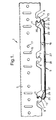
- Figure 1 shows a portion of a first ceiling panel assembly 1 having a laterally elongate carrier beam 3 which can hold a plurality of longitudinally elongate ceiling panels, generally, 5, of which only the longitudinal end of one panel 5 is shown.
- the carrier beam 3 has a plurality of prongs 7 spaced along its length.
- the prongs 7 each include at least one laterally open recess 9, preferably two laterally open recesses 9 on laterally opposite sides, to accommodate beads 11 on confronting upstanding inturned flanges, generally 13, on laterally opposite sides of each panel 5.
- the carrier 3 is also preferably provided with regularly spaced slots 15 and/or openings 17 which can be used for mounting the carrier on a building structure (not shown) or provide markings for shortening the carrier 3 at predefined locations.
- a panel connector 19 of this invention which includes a base member 21 and a hold down member 23, engages the ceiling panel 5. Laterally opposite sides of the base member 21 have a first pair of upstanding marginal edges 25 held between, and engaging, the opposite inturned flanges 13 of the ceiling panel 5 when the base member 21 lies substantially directly atop a substantially flat, central web portion 27 ofthe ceiling panel 5.
- the first pair of opposite marginal edges 25 is adapted to cooperate with the inturned flanges 13 of the ceiling panel 5 to laterally center the base member 21 on the ceiling panel 5.
- laterally opposite sides of the hold down member 23 have a second pair of upstanding marginal edges 29 that are held between, and engage, the opposite inturned flanges 13 of the ceiling panel 5 and are spaced away above the first pair of opposite marginal edges 25 when the hold down member 23 lies directly atop the base member 21 which lies directly atop the central web portion 27 of the ceiling panel 5.
- Each of the second pair of opposite marginal edges 29 is positioned on the free end of an upwardly biased, resilient side portion 37 ofthe hold down member 23 and is likewise adapted to cooperate with the opposite inturned flanges 13 of the ceiling panel 5 to laterally and vertically center the hold down member 23 on the ceiling panel 5 and on the base member 21, sandwiched between them.
- the opposite inturned flanges 13 of each ceiling panel 5 preferably have a generally U-shaped cross-section, as shown in Figure 1, where they engage the upstanding opposite marginal edges 25, 29 of the base member 21 and hold down member 23.
- the preferred U-shaped cross-section ofthe opposite inturned flanges 13 provides a generally inwardly-directed free end portion on the flange 13 on each lateral side of the ceiling panel, directed towards the inwardly-directed free end portion of the flange 13 on the other lateral side ofthe ceiling panel 5.
- Figure 1 also shows that the central body 33 of the base member 21 has a longitudinally-and downwardly-extending central dimple or depression 31.
- the depression 31 is urged against the underlying central web portion 27 of the ceiling panel 5 when the upstanding opposite marginal edges 25 of the base member 21 engage the confronting opposite inturned flanges 13 of the ceiling panel 5 as described below with regard to Figures 4 and 6.
- Figure 2 shows one longitudinal end of the panel connector 19 engaging a longitudinal end of a first ceiling panel 5A before the other longitudinal end of the panel connector 19 engages the adjacent longitudinal end of a second ceiling panel 5B to form a ceiling panel assembly 1 of this invention.
- the base member 21 of the panel connector 19 has a substantially flat, central body 33 which will overlie the confronting central web portions 27A, 27B of the first and second ceiling panels 5A and 5B, and the first pair of opposite marginal edges 25 of the base member 21 will thereby be snugly engaged between the most widely separated portions of the confronting upstanding inturned flanges 13A, 13B on laterally opposite sides of each ceiling panel 5A and 5B.
- the hold down member 23 also has a substantially flat, central body 35 which overlies the flat central body 33 of the base member 21.
- the upstanding second pair of opposite marginal edges 29 of the hold down member 23 are each positioned on the free end of a resilient, upwardly biased, side portion 37 on laterally opposite sides ofthe central body 35 ofthe hold down member.
- the resilient side portions 37 of the hold down member 23 are particularly resilient in an upward direction, so that when the hold down member is held between confronting inwardly-directed U-shaped portions of the opposite inturned, flanges 13A, 13B ofthe adjacent ceiling panels 5A and 5B and the central body 33 of the base member 21, the resilient side portions 37 bias the central body 33 of the base member 21 downwardly against the underlying confronting central web portions 27A, 27B of the panels 5A, 5B.
- the hold down member 23 preferably is directly held on the base member 21 by tabs 39 that are integrally formed in the central body 33 of the base member and that extend through and engage apertures 41 in the central body 35 of the hold down member.
- the apertures 41 are dimensioned to be significantly larger in the lateral direction than are the tabs 39, so that there can be significant relative movement between the base member 21 and the hold down member 23 in the lateral direction.
- the apertures 41 are also dimensioned to not be significantly larger in the longitudinal direction than are the tabs 39, so that there cannot be significant relative movement between the base member 21 and the hold down member 23 in the longitudinal direction.
- the hold down member 23 preferably has a longitudinal length (parallel to its second pair of opposite marginal edges 29) which is smaller than the longitudinal length of the base member 21 (parallel to its first pair of opposite marginal edges 25).
- the hold down member 23 is also preferably provided with upwardly bent tabs 43 to facilitate manual positioning of the panel connector 19, once it is inserted in the abutting ends and web portions 27A, 27B ofthe adjacent panels 5A, 5B.
- FIG 3 shows the hold down member 23 of the panel connector 19 of this invention, isolated from the base member 21 (which is shown separately in Figure 4).
- the hold down member 23 is adapted to accommodate different positions of the base member 21 on the ceiling panel 5 in a ceiling panel assembly 1, as a result of the shape and size of the apertures 41 in the central body 35 ofthe hold down member and its resilient side portions 37 carrying its second pair of opposite marginal edges 29.
- the hold down member 23 also has upwardly bent tabs 43 for holding and manipulating just the hold down member or the entire panel connector 19.
- upwardly bent tabs for holding and manipulating the entire panel connector 19 could be provided on the central body 33 of the base member 21, but there would be a risk of such tabs showing through as a deformation on the visibly exposed side of the central web portion 27 of the ceiling panel 5.
- Figure 4 shows the base member 21 of the panel connector 19 of this invention. Its tabs 39 are shown in an upstanding position, ready to be received in the apertures 41 of the hold down member 23. Also shown in Figure 4 is the central depression 31 which projects downwardly from the central body 33 of the base member 21, so as to be able to engage the web portion 27 of the ceiling panel 5 in the ceiling panel assembly 1 as shown in Figure 1. It is preferred that additional longitudinally-extending depressions 45 and 47 are provided on both lateral sides ofthe central depression 31. The additional depressions 45 and 47 are preferably somewhat shorter and shallower than the central depression 31. As explained below in connection with Figure 6, the single central depression 31 or optionally the several depressions 31, 45, 47 can assist in vertically aligning the central web portions 27 of the adjacent ceiling panels 5.
- the additional depressions 45, 47 are also generally aligned with the tabs 39 of the base member 21, the additional depressions can assist in hiding any imperfections that may result from the tabs 39 being formed out of the material of the central body 33 and that could be seen from beneath the ceiling panels 5 when the central body is flush with the central web portion 27 of the ceiling panel 5. Such imperfections could, for example, be the apertures left in the central body 33 by the tabs 39, showing through on the visibly exposed side ofthe central web portion 27 of the ceiling panel 5. By lifting slightly the central web portion 27, this phenomenon can be prevented.
- Figure 5 shows the base member 21 of Figure 4 attached to the hold down member 23 of Figure 3 to form the assembled panel connector 19.
- the tabs 39 ofthe base member 21 have been bent longitudinally through another 90 degrees to engage the inwardly facing edges of the apertures 41 of the hold down member to hold the base member and hold down member together but allow them to slide somewhat laterally relative to one another.
- the flat central bodies 33, 35 of the base member 21 of Figure 4 and the hold down member 23 of Figure 3 closely overlie one another, although the marginal edges 29 of the hold down member are spaced substantially above the marginal edges 25 of the base member within the inturned flanges 13 of the underlying ceiling panel 5.
- Figure 6 shows the underside of the central web portion 27 of one of the ceiling panels 5 with the panel connector 19 inserted into a longitudinal end thereof. This is the view that would be visible in a room containing the ceiling panel assembly 1.
- Figures 1 and 6 particularly show the cooperation between the central depression 31 in the central body 33 of the base member 21 of the panel connector 19 and the central web portion 27 of one of the adjacent ceiling panels 5.
- the central web portion 27 of each of the adjacent ceiling panels 5 is forced by the central depression 31, acting on the cut longitudinal end of the central web portion 27, to curve slightly laterally outwardly. This slight curvature greatly enhances the alignment ofthe cut longitudinal ends of adjacent ceiling panels 5, when joined together by the panel connector 19, and so prevents the formation of shadow lines or gaps between such ends.
- the additional depressions 45, 47 can provide extra support for the curvature of the abutting cut longitudinal ends of the panels 5, and accordingly, such depressions 45, 47 are preferably smaller than the central depression 31 in accordance with the smaller degree of panel distortion that they resist.
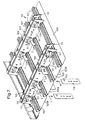
- FIG. 7 shows a second ceiling paneling assembly, generally 101, in a somewhat simplified arrangement, with two longitudinally elongate carrier beams 103.
- the carrier beams 103 are arranged parallel to one another and, for the purpose of illustration, are shown spaced closer together than they would be in covering an actual ceiling.
- Transverse to the longitudinal axes of the carrier beams 103 are a plurality of laterally elongate panels, generally 105, in side-by-side relationship.
- the panels 105 have in-turned marginal side flanges 107 which are engaged by support lugs (not visible in Figure 7, but generally referenced 129 in Figure 8) on the carrier beams 103.
- the carrier beams 103 each have an elongate body 109 with at least one downwardly depending flange 111, preferably two downwardly depending flanges 111,112.
- a plurality of upstanding locking clips, generally 113, are slidably attached to an exterior lateral face 114 of one of the depending flanges 111 of each carrier beam 103 in the vicinity of the support lugs (129 in Figure 8) and hold the side-by-side side flanges 107 of a pair of adjacent panels 105.
- each carrier beam 103 is provided with pairs of adjacent vertical slots 115, in which a pair of arms 117,118 on opposite sides of each locking clip 113 are vertically slidable.
- the configuration and shape of the arms 117,118 allow the clips 113 to engage the one depending flange 111 of each carrier beam 103 by hooking one arm 117 into one of a pair of vertical slots 115 while maneuvering its other arm 118 in the other vertical slot 115 of the pair as indicated by arrow A in Figure 7.
- the locking clip 113 can be slid downwardly in the slots 115 in the direction of arrow D to engage the side-by-side side flanges 107 of a pair of adjacent panels 105 to securely hold them in position on the carrier beam.
- Figure 7 also shows the locking of a last panel 105A to be installed in the second ceiling panel assembly 101 and the use of a tool 119 for accomplishing this.
- the last to-be-installed panel 105A positioned on all the carrier beams 103 and with all the previously fitted panels 105 locked by sliding downwardly the locking clips 113 above them, the locking clips 113 on the carrier beams for the last to-be-installed panel 105A can no longer be reached by hand.
- Locking of the last to-be-installed panel 105A is effected by first inserting the tool 119 between the abutting side flanges 107 of the last to-be-installed panel 105A and one of the longitudinally adjacent, previously installed panels 105B as indicated by arrow B. Then, the tool 119 is slid laterally towards an adjacent carrier beam 103 and a first upstanding locking clip 113 on the exterior lateral face 114 of its depending flange leg 111, between the two panels 105A, 105B to be fastened together first. The first locking clip 113 can then be engaged by means of a tab 121 extending frontally from about the middle ofthe locking clip, away from the one depending flange 111 of the adjacent carrier beam 103. The tab 121 is adapted to be accommodated in a recess 123 ofthe tool 119.
- the tool 119 is conveniently formed from a flat metal, preferably steel, strip.
- the tool 119 is adapted to be moved towards the adjacent carrier beam 103, with the flat sides and recess 123 of the tool extending laterally, between the somewhat resilient abutting side flanges 107 of the two panels 105A, 105B to be fastened together first, without damaging them.
- the tab 121 of the first locking clip 113 is moved downwardly in the direction of arrow D by moving the tool downwardly.
- This downward movement of the tab 121 and thereby the first locking clip 113 positions the abutting side flanges 107 of the two panels 105A, 105B, to be fastened together first, between a pair of downwardly- extending legs 125, 127 on opposite sides of the bottom of the first locking clip 113, which is the locking position of the locking clip 113 as described in more detail below with reference to Figure 8.
- the tool 119 is slid laterally away from the locking clip in accordance with arrow E, and the tool can thereafter be retracted by moving it downwardly in accordance with arrow F.
- Figure 8 shows three adjacent panels 105 of the second ceiling paneling assembly 101.
- the abutting in-turned side flanges 107 ofthe panels 105 are engaged by support lugs 129 formed on the depending flange 111 of one of the carrier beams 103, which flange 111 carries the locking clips 113 on the one carrier beam 103.
- the support lugs 129 are spaced along the length of the carrier beam 103, and each support lug has a stem portion 131 and two oppositely extending, support surfaces 133, 135.
- the support surfaces 133, 135 are each spaced vertically from an adjacent portion of the depending flange 111 and are adapted to receive an outwardly directed bead 137 on the free edge of each of the confronting side flanges 107 ofthe adjacent panels 105.
- Figure 8 also shows two locking clips 113 on the one carrier beam 103.
- the right-hand locking clip 113 is shown in its uppermost or inactive position.
- the left-hand locking clip is shown in its lowermost or active position with its legs 125, 127 adjacent to, and on longitudinally opposite sides of, a pair of outwardly directed beads 137 of the confronting side flanges 107 of adjacent panels 105, thereby preventing the outwardly directed beads 137 of the adjacent panels 105 from becoming disengaged from the support lug 129.
- at about the middle of the length of each leg 125, 127 is a frontally-extending knee portion 139.
- each knee portion 139 engages a lower edge 141 of a recess 143 that is in the depending flange 111 of the carrier beam 103 and that surrounds the support lug 129.
- the knee portions 139 thereby hold the left-hand locking clip 113 in its lowermost, active position to prevent it from being accidentally dislocated from its locking position on the exterior lateral face 114 of the depending flange 111, holding together two side-by-side side flanges 107 of a pair of adjacent panels 105.
- Manual movement of each locking clip 113, between its inactive and active positions, is facilitated by a frontally-extending finger grip 145 on top of the locking clip.
- FIGS 9 and 10 show the upstanding locking clip 113 in more detail from the front and back.
- the locking clip 113 has a main body 147, from which the pair of arms 117, 118 and the pair of legs 125, 127 extend generally in the plane of the main body.
- the arms 117,118 are on opposite sides ofthe main body 147 and extend generally away from its opposite sides.
- the legs 125,127 are on opposite sides of the bottom of the main body and extend generally downwardly.
- Also on the main body 147 is the frontally-extending tab 121, located vertically and horizontally between its arms 117, 118 and legs 125, 127, and on top of the main body portion is the frontally- extending finger grip 145.
- the arms 117, 118 each have a rear arm portion 149, an inwardly- and frontally- extending front arm portion 151 and a frontally-extending hand portion 153.
- a tongue 155 which is adapted to engage behind the carrier flange 111 at the bottom of the vertical slot 115 when the locking clip 113 is in its lowermost locked position.
- front arm portions 151 also provide sufficient guidance to the locking clip 113 during the first portion of its downward sliding movement until its tongues 155 have reached the bottom of the vertical slots 115.
- the lower end of each tongue 155 is rounded or chamfered to enable engagement with some resilient pressure.
- the function ofthe frontally-extending hands 153 is to provide guidance upon initial engagement with the carrier beam 103 as explained in connection with arrow A of Figure 7.
- Figures 9 and 10 also show that the finger grip 145 is spaced above the main body portion 147 by a neck 157. As seen in Figures 7 and 8, the neck 157 spaces the finger grip 145, so that it is flush with the top of the carrier body 109 so as to allow the unlocked position of the locking clips 113 to be readilly recognisable, visually.
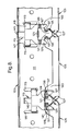
- Figure 11 shows the demounting of a first panel 105 and the use of the tool 119 for this purpose.
- the tool 119 is first inserted in the direction of arrow E between the abutting side flanges 107 at the joint of neighboring panels 105, which will resiliently allow the flat strip-like tool 119 to pass between them.
- the tool 119 far enough inserted between the adjacent side flanges 107, it can be moved in the direction of arrow F towards the adjacent carrier beam 103, so as to engage the tab 121 ofthe locking clip 113 in the recess 123 ofthe tool 119.
- the tool 119 With the tab 121 engaged in the recess 123, the tool 119 is moved further upwardly in the direction of arrow G, and this will then move the particular locking clip 113 to its unlocked position. As shown elsewhere in Figure 11, retraction of the tool 119 after unlocking one of the locking clips 113 is first in the direction of arrow H to disengage the tab 121 from the recess 123 and thereafter in the direction of arrow I to retract the tool from between the adjacent panel flanges 107.
- the tool 119 is similarly inserted between the abutting side flanges 107 at the opposite side of this first panel 105, to be removed. Subsequent to unlocking the locking clips 113 on this other side of the first panel 105, the tool 119, while still inserted between the abutting side flanges 107, is pivoted in the direction of arrow J to free the outwardly directed bead 137 of the panel from engagement with the confronting support lug 129. With the first panel removed, removing any further panels 105 is straight forward, as the other locking clips 113 can now each be reached manually and unlocked, as required, using their finger grips 145.
Landscapes
- Engineering & Computer Science (AREA)
- Architecture (AREA)
- Physics & Mathematics (AREA)
- Electromagnetism (AREA)
- Civil Engineering (AREA)
- Structural Engineering (AREA)
- Finishing Walls (AREA)
- Connection Of Plates (AREA)
- Clamps And Clips (AREA)
- Joining Of Building Structures In Genera (AREA)
- Slide Fasteners, Snap Fasteners, And Hook Fasteners (AREA)
- Adornments (AREA)
- Liquid Developers In Electrophotography (AREA)
- Disintegrating Or Milling (AREA)
- Cutting Tools, Boring Holders, And Turrets (AREA)
- Mechanical Coupling Of Light Guides (AREA)
- Piezo-Electric Or Mechanical Vibrators, Or Delay Or Filter Circuits (AREA)
- Coupling Device And Connection With Printed Circuit (AREA)
Priority Applications (2)
| Application Number | Priority Date | Filing Date | Title |
|---|---|---|---|
| EP99307272A EP0987378B1 (de) | 1998-09-15 | 1999-09-14 | Endpaneelverbinder |
| EP05000470A EP1522646B1 (de) | 1998-09-15 | 1999-09-14 | Klemmhalter |
Applications Claiming Priority (5)
| Application Number | Priority Date | Filing Date | Title |
|---|---|---|---|
| EP98203081 | 1998-09-15 | ||
| EP98203081 | 1998-09-15 | ||
| EP98203221 | 1998-09-25 | ||
| EP98203221 | 1998-09-25 | ||
| EP99307272A EP0987378B1 (de) | 1998-09-15 | 1999-09-14 | Endpaneelverbinder |
Related Child Applications (1)
| Application Number | Title | Priority Date | Filing Date |
|---|---|---|---|
| EP05000470A Division EP1522646B1 (de) | 1998-09-15 | 1999-09-14 | Klemmhalter |
Publications (3)
| Publication Number | Publication Date |
|---|---|
| EP0987378A2 true EP0987378A2 (de) | 2000-03-22 |
| EP0987378A3 EP0987378A3 (de) | 2001-07-11 |
| EP0987378B1 EP0987378B1 (de) | 2005-04-27 |
Family
ID=26150679
Family Applications (2)
| Application Number | Title | Priority Date | Filing Date |
|---|---|---|---|
| EP99307272A Expired - Lifetime EP0987378B1 (de) | 1998-09-15 | 1999-09-14 | Endpaneelverbinder |
| EP05000470A Expired - Lifetime EP1522646B1 (de) | 1998-09-15 | 1999-09-14 | Klemmhalter |
Family Applications After (1)
| Application Number | Title | Priority Date | Filing Date |
|---|---|---|---|
| EP05000470A Expired - Lifetime EP1522646B1 (de) | 1998-09-15 | 1999-09-14 | Klemmhalter |
Country Status (6)
| Country | Link |
|---|---|
| US (1) | US6336302B1 (de) |
| EP (2) | EP0987378B1 (de) |
| AT (2) | ATE344858T1 (de) |
| DE (2) | DE69924933T2 (de) |
| DK (2) | DK0987378T3 (de) |
| ES (2) | ES2237889T3 (de) |
Cited By (1)
| Publication number | Priority date | Publication date | Assignee | Title |
|---|---|---|---|---|
| US20190024373A1 (en) * | 2015-09-08 | 2019-01-24 | Hunter Douglas Industries B.V. | Carrier for a linear ceiling panel |
Families Citing this family (11)
| Publication number | Priority date | Publication date | Assignee | Title |
|---|---|---|---|---|
| US6684929B2 (en) | 2002-02-15 | 2004-02-03 | Steelcase Development Corporation | Panel system |
| US7841142B2 (en) * | 2006-11-22 | 2010-11-30 | Steelcase Inc. | Stack-on panel assembly |
| US8019526B2 (en) * | 2007-12-07 | 2011-09-13 | GM Global Technology Operations LLC | Adapter phasor control hold duty cycle system for an engine |
| USD656251S1 (en) * | 2010-12-03 | 2012-03-20 | USG Interiors, LLC. | Seismic expansion sleeve for suspended ceilings |
| CA3037878A1 (en) | 2016-09-23 | 2018-03-29 | Armstrong World Industries, Inc. | Panel system and support member for use with the same |
| KR101802445B1 (ko) * | 2017-03-21 | 2017-11-29 | 주식회사 조은데코 | 마감패널 고정장치 |
| US10738465B2 (en) * | 2017-04-27 | 2020-08-11 | Usg Interiors, Llc | Suspended baffle system |
| GB2569346B (en) * | 2017-12-14 | 2020-09-09 | Hunter Douglas Ind Bv | System for mounting a plurality of panels |
| CA3048391A1 (en) | 2018-07-04 | 2020-01-04 | Hunter Douglas Industries B.V. | Ceiling system |
| US11486141B2 (en) * | 2020-03-25 | 2022-11-01 | Awi Licensing Llc | Ceiling system and carrier component thereof |
| US20250092676A1 (en) * | 2023-09-14 | 2025-03-20 | Usg Interiors, Llc | Linear metal ceilings |
Citations (5)
| Publication number | Priority date | Publication date | Assignee | Title |
|---|---|---|---|---|
| CH349398A (fr) | 1958-03-04 | 1960-10-15 | Isolation Thermique Et Acousti | Procédé de montage de panneaux métalliques isolants |
| GB982775A (en) | 1960-07-14 | 1965-02-10 | Hunter Douglas Int Quebec Ltd | A connection between the ends of two building panels |
| US3645051A (en) | 1969-10-24 | 1972-02-29 | Frank S Kolesar | Ceiling structure |
| US4328653A (en) | 1980-01-23 | 1982-05-11 | Levolor Lorentzen, Inc. | Ceiling panel clip |
| EP0137591B1 (de) | 1983-08-16 | 1989-03-22 | Hunter Douglas Industries B.V. | Verkleidungssystem und Träger dafür |
Family Cites Families (19)
| Publication number | Priority date | Publication date | Assignee | Title |
|---|---|---|---|---|
| US2585082A (en) * | 1947-01-02 | 1952-02-12 | Jr George H Bollinger | Insulated metal panel |
| US2648102A (en) * | 1950-11-03 | 1953-08-11 | Level Line Ceilings Inc | Ceiling construction |
| NL6401479A (de) | 1964-02-18 | 1965-08-19 | ||
| US3606720A (en) * | 1968-05-20 | 1971-09-21 | Cookson Sheet Metal Dev Ltd | Roofing and siding sheets and the like and fastening means therefor |
| US3640557A (en) * | 1969-12-19 | 1972-02-08 | Armstrong Cork Co | Expansion splice |
| US4063393A (en) * | 1973-05-10 | 1977-12-20 | Toti Andrew J | Panel assembly structure and procedure for assembling same |
| FR2265032A1 (de) * | 1974-03-20 | 1975-10-17 | Vincens Rene | |
| US4114338A (en) * | 1977-05-09 | 1978-09-19 | Armco Steel Corporation | Reinforcing plate for overlapped joints |
| US4257206A (en) * | 1978-12-28 | 1981-03-24 | Donn Incorporated | Fire rated ceiling |
| GB2052594B (en) * | 1979-05-17 | 1983-03-16 | Metal Ceilings Ltd | Metal panelled ceiling |
| US4494346A (en) * | 1982-11-01 | 1985-01-22 | Alcan Aluminum Corporation | Ceiling system and panel-securing device therefor |
| CA1243181A (en) * | 1985-01-08 | 1988-10-18 | Michael Slapsys | Linear panel ceilings and the like |
| US4987715A (en) * | 1986-03-31 | 1991-01-29 | Chicago Metallic Corporation | Parallel beam system |
| CH674537A5 (en) * | 1987-11-05 | 1990-06-15 | Hans Aebin | Suspended ceiling - has spring mating faces on ceiling section sidewalls and bosses on supporting members |
| US4949523A (en) * | 1988-03-28 | 1990-08-21 | Kassem Gary M | Non-penetrating elastomeric membrane anchoring system |
| US5481839A (en) * | 1992-09-09 | 1996-01-09 | Kawneer Company, Inc. | Glazed panel wall construction and method for assembly thereof |
| CN1068087C (zh) * | 1992-11-06 | 2001-07-04 | 东陶机器株式会社 | 镶板连接机构 |
| DE69406855T2 (de) * | 1993-07-09 | 1998-03-12 | Hunter Douglas Ind Bv | Verkleidungsbauweise und eine Tragschiene dafür |
| US5842315A (en) * | 1997-03-24 | 1998-12-01 | Tung Yik Trading Co., Ltd. | Corrugated board structure |
-
1999
- 1999-09-14 DE DE69924933T patent/DE69924933T2/de not_active Expired - Lifetime
- 1999-09-14 EP EP99307272A patent/EP0987378B1/de not_active Expired - Lifetime
- 1999-09-14 AT AT05000470T patent/ATE344858T1/de active
- 1999-09-14 EP EP05000470A patent/EP1522646B1/de not_active Expired - Lifetime
- 1999-09-14 ES ES99307272T patent/ES2237889T3/es not_active Expired - Lifetime
- 1999-09-14 DK DK99307272T patent/DK0987378T3/da active
- 1999-09-14 AT AT99307272T patent/ATE294294T1/de active
- 1999-09-14 ES ES05000470T patent/ES2271913T3/es not_active Expired - Lifetime
- 1999-09-14 DE DE69933951T patent/DE69933951T2/de not_active Expired - Lifetime
- 1999-09-14 DK DK05000470T patent/DK1522646T3/da active
- 1999-09-15 US US09/396,544 patent/US6336302B1/en not_active Expired - Fee Related
Patent Citations (5)
| Publication number | Priority date | Publication date | Assignee | Title |
|---|---|---|---|---|
| CH349398A (fr) | 1958-03-04 | 1960-10-15 | Isolation Thermique Et Acousti | Procédé de montage de panneaux métalliques isolants |
| GB982775A (en) | 1960-07-14 | 1965-02-10 | Hunter Douglas Int Quebec Ltd | A connection between the ends of two building panels |
| US3645051A (en) | 1969-10-24 | 1972-02-29 | Frank S Kolesar | Ceiling structure |
| US4328653A (en) | 1980-01-23 | 1982-05-11 | Levolor Lorentzen, Inc. | Ceiling panel clip |
| EP0137591B1 (de) | 1983-08-16 | 1989-03-22 | Hunter Douglas Industries B.V. | Verkleidungssystem und Träger dafür |
Cited By (5)
| Publication number | Priority date | Publication date | Assignee | Title |
|---|---|---|---|---|
| US20190024373A1 (en) * | 2015-09-08 | 2019-01-24 | Hunter Douglas Industries B.V. | Carrier for a linear ceiling panel |
| US10683664B2 (en) * | 2015-09-08 | 2020-06-16 | Hunter Douglas Inc. | Carrier for a linear ceiling panel |
| US11091910B2 (en) | 2015-09-08 | 2021-08-17 | Hunter Douglas Industries B.V. | Carrier for a linear ceiling panel |
| CN113404204A (zh) * | 2015-09-08 | 2021-09-17 | 亨特道格拉斯工业公司 | 用于线性天花板镶板的托架 |
| CN113404204B (zh) * | 2015-09-08 | 2023-04-21 | 亨特道格拉斯工业公司 | 用于线性天花板镶板的托架 |
Also Published As
| Publication number | Publication date |
|---|---|
| ATE294294T1 (de) | 2005-05-15 |
| ES2271913T3 (es) | 2007-04-16 |
| DK1522646T3 (da) | 2007-03-19 |
| DE69933951T2 (de) | 2007-03-08 |
| EP0987378A3 (de) | 2001-07-11 |
| DE69924933D1 (de) | 2005-06-02 |
| DE69933951D1 (de) | 2006-12-21 |
| ES2237889T3 (es) | 2005-08-01 |
| EP1522646A1 (de) | 2005-04-13 |
| US6336302B1 (en) | 2002-01-08 |
| EP1522646B1 (de) | 2006-11-08 |
| DK0987378T3 (da) | 2005-08-29 |
| ATE344858T1 (de) | 2006-11-15 |
| DE69924933T2 (de) | 2006-02-23 |
| EP0987378B1 (de) | 2005-04-27 |
Similar Documents
| Publication | Publication Date | Title |
|---|---|---|
| CA2032646C (en) | Landscape edging system | |
| EP0987378B1 (de) | Endpaneelverbinder | |
| CA2246899C (en) | Suspended ceiling cross tee end connector | |
| CA2645824C (en) | Improved connections for suspended ceiling system | |
| US7223043B1 (en) | Structural members and joining arrangements therefor | |
| US7010894B1 (en) | Covering, covering elements and installing and disassembling method | |
| US3677589A (en) | Field installation clip for exposed grid systems | |
| US5651224A (en) | Architectural molding assembly with clamping brackets | |
| EP0667929B1 (de) | Bauweise für aufgehängten decken, wände und trennwände | |
| US20170342736A1 (en) | Track system for supporting wall studs | |
| CA2319858A1 (en) | Fastened structure of siding boards | |
| US5732521A (en) | Longitudinal or transverse support for ceiling panelling | |
| US20030182894A1 (en) | Method of installing a set of ceiling panels | |
| EP1561875A1 (de) | Bandraster-System | |
| CA1120234A (en) | Accessible-demountable support system for wall paneling and reversible clip means used therein | |
| CA2533247C (en) | Cross panel | |
| US6305144B1 (en) | Window frame and method | |
| JP2600244Y2 (ja) | 天井下地格子枠の結合構造 | |
| EP1261782B1 (de) | Verfahren zur installation von deckenpaneelen | |
| WO2001002666A1 (en) | A clip | |
| CN207714562U (zh) | 用于支撑墙体立柱的轨道系统 | |
| JP2570593Y2 (ja) | 格子状天井枠の結合構造 | |
| EP4222326A1 (de) | Verbindungssystem für den aufbau einer trennwand | |
| GB2369627A (en) | Cross runner for suspended grid ceiling | |
| AU4508500A (en) | A clip |
Legal Events
| Date | Code | Title | Description |
|---|---|---|---|
| PUAI | Public reference made under article 153(3) epc to a published international application that has entered the european phase |
Free format text: ORIGINAL CODE: 0009012 |
|
| AK | Designated contracting states |
Kind code of ref document: A2 Designated state(s): AT BE CH CY DE DK ES FI FR GB GR IE IT LI LU MC NL PT SE |
|
| AX | Request for extension of the european patent |
Free format text: AL;LT;LV;MK;RO;SI |
|
| PUAL | Search report despatched |
Free format text: ORIGINAL CODE: 0009013 |
|
| AK | Designated contracting states |
Kind code of ref document: A3 Designated state(s): AT BE CH CY DE DK ES FI FR GB GR IE IT LI LU MC NL PT SE |
|
| AX | Request for extension of the european patent |
Free format text: AL;LT;LV;MK;RO;SI |
|
| 17P | Request for examination filed |
Effective date: 20010824 |
|
| AKX | Designation fees paid |
Free format text: AT BE CH CY DE DK ES FI FR GB GR IE IT LI LU MC NL PT SE |
|
| 17Q | First examination report despatched |
Effective date: 20031217 |
|
| RTI1 | Title (correction) |
Free format text: PANEL END CONNECTOR |
|
| GRAP | Despatch of communication of intention to grant a patent |
Free format text: ORIGINAL CODE: EPIDOSNIGR1 |
|
| GRAS | Grant fee paid |
Free format text: ORIGINAL CODE: EPIDOSNIGR3 |
|
| GRAA | (expected) grant |
Free format text: ORIGINAL CODE: 0009210 |
|
| AK | Designated contracting states |
Kind code of ref document: B1 Designated state(s): AT BE CH CY DE DK ES FI FR GB GR IE IT LI LU MC NL PT SE |
|
| PG25 | Lapsed in a contracting state [announced via postgrant information from national office to epo] |
Ref country code: FI Free format text: LAPSE BECAUSE OF FAILURE TO SUBMIT A TRANSLATION OF THE DESCRIPTION OR TO PAY THE FEE WITHIN THE PRESCRIBED TIME-LIMIT Effective date: 20050427 |
|
| REG | Reference to a national code |
Ref country code: GB Ref legal event code: FG4D |
|
| REG | Reference to a national code |
Ref country code: CH Ref legal event code: EP |
|
| REG | Reference to a national code |
Ref country code: IE Ref legal event code: FG4D |
|
| REF | Corresponds to: |
Ref document number: 69924933 Country of ref document: DE Date of ref document: 20050602 Kind code of ref document: P |
|
| REG | Reference to a national code |
Ref country code: CH Ref legal event code: NV Representative=s name: ROTTMANN, ZIMMERMANN + PARTNER AG |
|
| PG25 | Lapsed in a contracting state [announced via postgrant information from national office to epo] |
Ref country code: SE Free format text: LAPSE BECAUSE OF FAILURE TO SUBMIT A TRANSLATION OF THE DESCRIPTION OR TO PAY THE FEE WITHIN THE PRESCRIBED TIME-LIMIT Effective date: 20050727 Ref country code: GR Free format text: LAPSE BECAUSE OF FAILURE TO SUBMIT A TRANSLATION OF THE DESCRIPTION OR TO PAY THE FEE WITHIN THE PRESCRIBED TIME-LIMIT Effective date: 20050727 |
|
| REG | Reference to a national code |
Ref country code: ES Ref legal event code: FG2A Ref document number: 2237889 Country of ref document: ES Kind code of ref document: T3 |
|
| REG | Reference to a national code |
Ref country code: DK Ref legal event code: T3 |
|
| PG25 | Lapsed in a contracting state [announced via postgrant information from national office to epo] |
Ref country code: IE Free format text: LAPSE BECAUSE OF NON-PAYMENT OF DUE FEES Effective date: 20050914 Ref country code: CY Free format text: LAPSE BECAUSE OF FAILURE TO SUBMIT A TRANSLATION OF THE DESCRIPTION OR TO PAY THE FEE WITHIN THE PRESCRIBED TIME-LIMIT Effective date: 20050914 |
|
| PG25 | Lapsed in a contracting state [announced via postgrant information from national office to epo] |
Ref country code: MC Free format text: LAPSE BECAUSE OF NON-PAYMENT OF DUE FEES Effective date: 20050930 Ref country code: LU Free format text: LAPSE BECAUSE OF NON-PAYMENT OF DUE FEES Effective date: 20050930 |
|
| PG25 | Lapsed in a contracting state [announced via postgrant information from national office to epo] |
Ref country code: PT Free format text: LAPSE BECAUSE OF FAILURE TO SUBMIT A TRANSLATION OF THE DESCRIPTION OR TO PAY THE FEE WITHIN THE PRESCRIBED TIME-LIMIT Effective date: 20051010 |
|
| PLBE | No opposition filed within time limit |
Free format text: ORIGINAL CODE: 0009261 |
|
| STAA | Information on the status of an ep patent application or granted ep patent |
Free format text: STATUS: NO OPPOSITION FILED WITHIN TIME LIMIT |
|
| ET | Fr: translation filed | ||
| 26N | No opposition filed |
Effective date: 20060130 |
|
| REG | Reference to a national code |
Ref country code: IE Ref legal event code: MM4A |
|
| PGFP | Annual fee paid to national office [announced via postgrant information from national office to epo] |
Ref country code: AT Payment date: 20100910 Year of fee payment: 12 |
|
| REG | Reference to a national code |
Ref country code: CH Ref legal event code: PFA Owner name: HUNTER DOUGLAS INDUSTRIES B.V. Free format text: HUNTER DOUGLAS INDUSTRIES B.V.#PIEKSTRAAT 2#3071 EL ROTTERDAM (NL) -TRANSFER TO- HUNTER DOUGLAS INDUSTRIES B.V.#PIEKSTRAAT 2#3071 EL ROTTERDAM (NL) |
|
| REG | Reference to a national code |
Ref country code: AT Ref legal event code: MM01 Ref document number: 294294 Country of ref document: AT Kind code of ref document: T Effective date: 20110914 |
|
| PG25 | Lapsed in a contracting state [announced via postgrant information from national office to epo] |
Ref country code: AT Free format text: LAPSE BECAUSE OF NON-PAYMENT OF DUE FEES Effective date: 20110914 |
|
| REG | Reference to a national code |
Ref country code: FR Ref legal event code: PLFP Year of fee payment: 17 |
|
| REG | Reference to a national code |
Ref country code: FR Ref legal event code: PLFP Year of fee payment: 18 |
|
| REG | Reference to a national code |
Ref country code: CH Ref legal event code: PCAR Free format text: NEW ADDRESS: GARTENSTRASSE 28 A, 5400 BADEN (CH) |
|
| REG | Reference to a national code |
Ref country code: FR Ref legal event code: PLFP Year of fee payment: 19 |
|
| REG | Reference to a national code |
Ref country code: FR Ref legal event code: PLFP Year of fee payment: 20 |
|
| PGFP | Annual fee paid to national office [announced via postgrant information from national office to epo] |
Ref country code: DE Payment date: 20180904 Year of fee payment: 20 Ref country code: FR Payment date: 20180813 Year of fee payment: 20 Ref country code: IT Payment date: 20180919 Year of fee payment: 20 |
|
| PGFP | Annual fee paid to national office [announced via postgrant information from national office to epo] |
Ref country code: GB Payment date: 20180912 Year of fee payment: 20 Ref country code: NL Payment date: 20180912 Year of fee payment: 20 Ref country code: DK Payment date: 20180911 Year of fee payment: 20 Ref country code: CH Payment date: 20180913 Year of fee payment: 20 Ref country code: BE Payment date: 20180814 Year of fee payment: 20 |
|
| PGFP | Annual fee paid to national office [announced via postgrant information from national office to epo] |
Ref country code: ES Payment date: 20181001 Year of fee payment: 20 |
|
| REG | Reference to a national code |
Ref country code: CH Ref legal event code: PL |
|
| REG | Reference to a national code |
Ref country code: DE Ref legal event code: R071 Ref document number: 69924933 Country of ref document: DE |
|
| REG | Reference to a national code |
Ref country code: DK Ref legal event code: EUP Effective date: 20190914 |
|
| REG | Reference to a national code |
Ref country code: NL Ref legal event code: MK Effective date: 20190913 |
|
| REG | Reference to a national code |
Ref country code: GB Ref legal event code: PE20 Expiry date: 20190913 |
|
| REG | Reference to a national code |
Ref country code: BE Ref legal event code: MK Effective date: 20190914 |
|
| PG25 | Lapsed in a contracting state [announced via postgrant information from national office to epo] |
Ref country code: GB Free format text: LAPSE BECAUSE OF EXPIRATION OF PROTECTION Effective date: 20190913 |
|
| REG | Reference to a national code |
Ref country code: ES Ref legal event code: FD2A Effective date: 20200805 |
|
| PG25 | Lapsed in a contracting state [announced via postgrant information from national office to epo] |
Ref country code: ES Free format text: LAPSE BECAUSE OF EXPIRATION OF PROTECTION Effective date: 20190915 |