EP0987395A2 - Scharnieranordnung - Google Patents
Scharnieranordnung Download PDFInfo
- Publication number
- EP0987395A2 EP0987395A2 EP99306029A EP99306029A EP0987395A2 EP 0987395 A2 EP0987395 A2 EP 0987395A2 EP 99306029 A EP99306029 A EP 99306029A EP 99306029 A EP99306029 A EP 99306029A EP 0987395 A2 EP0987395 A2 EP 0987395A2
- Authority
- EP
- European Patent Office
- Prior art keywords
- parts
- detent
- pivot assembly
- pivot
- engagement
- Prior art date
- Legal status (The legal status is an assumption and is not a legal conclusion. Google has not performed a legal analysis and makes no representation as to the accuracy of the status listed.)
- Granted
Links
- 238000010276 construction Methods 0.000 description 18
- 230000004048 modification Effects 0.000 description 2
- 238000012986 modification Methods 0.000 description 2
- 230000000694 effects Effects 0.000 description 1
Images






Classifications
-
- A—HUMAN NECESSITIES
- A47—FURNITURE; DOMESTIC ARTICLES OR APPLIANCES; COFFEE MILLS; SPICE MILLS; SUCTION CLEANERS IN GENERAL
- A47C—CHAIRS; SOFAS; BEDS
- A47C1/00—Chairs adapted for special purposes
- A47C1/14—Beach chairs ; Chairs for outdoor use, e.g. chairs for relaxation or sun-tanning
- A47C1/143—Chaise lounges
-
- A—HUMAN NECESSITIES
- A47—FURNITURE; DOMESTIC ARTICLES OR APPLIANCES; COFFEE MILLS; SPICE MILLS; SUCTION CLEANERS IN GENERAL
- A47C—CHAIRS; SOFAS; BEDS
- A47C4/00—Foldable, collapsible or dismountable chairs
- A47C4/28—Folding chairs with flexible coverings for the seat or back elements
- A47C4/42—Folding chairs with flexible coverings for the seat or back elements having a frame made of metal
- A47C4/44—Folding chairs with flexible coverings for the seat or back elements having a frame made of metal with legs pivotably connected to seat or underframe
-
- E—FIXED CONSTRUCTIONS
- E05—LOCKS; KEYS; WINDOW OR DOOR FITTINGS; SAFES
- E05D—HINGES OR SUSPENSION DEVICES FOR DOORS, WINDOWS OR WINGS
- E05D11/00—Additional features or accessories of hinges
- E05D11/10—Devices for preventing movement between relatively-movable hinge parts
- E05D11/1007—Devices for preventing movement between relatively-movable hinge parts with positive locking
Definitions
- the present invention is directed to a pivot assembly comprising two parts which are connected to one another by means of a pivot so that one is pivotable relative to the other, and a movable detent on one of the parts which can be moved into engagement with the other to retain the two parts in a predetermined relative angular position relative to one another, and out of such engagement to enable subsequent relative pivotal movement between the two parts.
- a detent comprising a sleeve with an internal screw threading engages an external screw threading on one of the said two parts, these screw threads engaging one another so that the movement of the detent is effected by rotating the two screw threads relative to one another.
- a sector plate is fixed to one of the said two parts and has a plurality of holes spaced apart around an arc close to the periphery of the sector plate.
- a pin on the other of the said two parts can be moved, in a direction parallel to the pivot axis, into engagement with any selective one of these holes.
- a disadvantage of these foregoing constructions of pivot assembly is that they are relatively difficult to effect engagement of the detent.
- a further disadvantage associated with the foregoing constructions is that they do not fix the said two parts relative to one another particularly well even when the detent is duly engaged.
- the present invention seeks to obviate one or more of the foregoing disadvantages.
- the present invention is directed to a pivot assembly having the construction set out in the opening paragraph of the present specification, in which the detent is slidable towards and away from the pivot for such engagement and disengagement of the detent with the said other part.
- the detent is in the form of a sleeve which surrounds a portion of the said one of the two parts adjacent to the pivot end thereof.
- a particularly rigid fixing between the two parts can be achieved if the detent has a flat surface which contacts a flat surface on the other of the said two parts when the detent is in such engagement.
- a particularly rigid fixing between the two parts can also be achieved if the detent is provided with a portion which is received in a hole or recess in the said other of the two parts.
- the said portion may extend from a flat surface on the detent which contacts a flat surface on the said other of the two parts when the detent is in such engagement.
- the detent is spring biased in a direction which urges it towards such engagement.
- the spring may be a helical spring surrounding one of the said two parts, in which case the latter may be provided with a shoulder to act as an abutment for one end of the helical spring.
- Such a pivot assembly may be part of a bank stick or rod support for use in angling having at least one leg which can be shifted from a storage position in which it is folded-up against another part of the support, and a position for use in which it extends outwardly from that part of the support, the leg and that other part of the support being held together by such a pivot assembly.
- the present invention extends to a chair or bedchair having a backrest attached to a seat portion thereof by means of such a pivot assembly.
- the bank stick support 10 shown in Figure 1 comprises a crossbar 12 to the ends of which are connected two pivot blocks 14 respectively.
- Two support legs 16 extend downwardly from each pivot block 14 in respective directions which are spaced apart from one another and from the crossbar 12.
- a bank stick receiving tube 18 extends centrally through each pivot block 14.
- the upper ends of the tubes 18 are each provided with a sleeve 20 and a locking screw and screw head 22 which passes transversely through the sleeve 20. This enables a bank stick to be inserted downwardly into a tube 18 to a desired height, whereupon the locking screw 22 can be rotated to fix the relative height of the bank stick.
- Each tube 18 is held in place itself by means of a locking screw 23 with entends through the pivot block 14.
- the crossbar 12 may be telescopic so that its length can be adjusted, for which purpose a further sleeve 24 may be provided at one of the ends of the crossbar 12 provided with a locking screw (not shown) like the one 22, to secure two parts of the crossbar 12 at a selected length.
- the crossbar 12, the two legs 16 and the tube 18 can all be brought parallel and adjacent to one another by adjusting the pivot block 14 so that they are positioned relative to one another as shown in Figure 2 for storage purposes.
- each of the legs 16 and the crossbar 12 are reduced in thickness at their pivot ends, the latter thereby being relatively flat and tongue-shaped.
- One tongue-shaped end of the crossbar 12 is labelled 25 in Figures 4 and 5, and one tongue-shaped end of a leg 16 is labelled 26 in Figure 6.
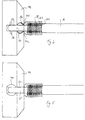
- the tongue-shaped end 25, or 26, is secured internally in the block 14 by means of a pivot pin 28 so that the leg or crossbar can pivot relative to the block 14 about the pin 28.
- Slots 30 and 32 are provided in the block to facilitate such pivoting and enable the tongue 25 or 26 to project outwardly from the block 14 at any angle in the range from a direction which is parallel to the tube 18 to one which is substantially at right angles thereto.
- Each block 14 is generally cylindrical, the height of the cylinder being relatively short compared to its diameter. Its intended lower periphery is chamfered to create a frustoconical surface 34 which is at about 30° to the cylindrical outer surface of the block.
- a generally circular hole or recess 36 is formed in the frustoconical surface 34 in registration with each slot 32 for each leg 16. Threaded on to each leg 16 adjacent to the pivot end thereof, and surrounding the leg at that location, there is a sleeve 38 having an internal diameter which slightly exceeds the external diameter of the leg 16 so that the sleeve 38 can slide longitudinally of the leg 16 in both directions.
- the sleeve 38 has an end 40 which abuts the tongue 26 and is formed with a generally circular projection 42. The latter engages the circular recess 36 as a close fit.
- the helical spring 43 extends within the sleeve 38 between an abutment shoulder 44 of the leg 16 and the internal side of the other end of the sleeve 38. It thereby urges the sleeve 38 towards the pivot 28.
- the end of the sleeve which is close to the pivot 26 abuts against the smaller of the flat main circular faces of the block 14.
- the leg 16 To change the position of the leg 16 to its position ready for use, it is simply pivoted about the pivot 28.
- the sleeve 38 as a result rides up the leg 16 against the force of the spring 43 until it clears the intended lower rim of the block 14, whereupon it starts to slide back towards the pivot.
- the action of the spring 43 is such as to snap the projection 42 into the recess 36. This releasably locks the leg 16 in a position relative to the block 14 in such a manner that the leg 16 is substantially 30° to the main flat surfaces of the block 14.
- the construction of the pivot connection between the crossbar 12 and the block 14 is precisely the same as between one of the legs 16 and the block 14, excepting only that the hole or recess 46 is in the cylindrical surface of the block 14 rather than in the frustoconical surface thereof, so that when the support is in a condition ready for use, it is generally parallel to the main flat surfaces of the block 14, and perpendicular to each tube 18.
- This bank stick or rod support in its condition ready for use can now be placed on the ground with the crossbar 12 generally horizontal, the tubes 18 generally vertically arranged and the leg 16 sloping downwardly, diverging from one another and from the crossbar 12 in the manner shown in Figure 1.
- the modified form of bank stick or rod support shown in Figure 7 has a block 14 which differs from that of the construction shown in Figures 1 to 6 with a view to reducing the total amount of material needed to make it.
- the modified block 14 comprises a sleeve portion 70 which receives one end of the crossbar 12 as a tight fit.
- the modified block also has a through hole 72 through which the associated tube 18 extends, locked at a selected height when the rod support is in use by means of the locking screw 74.
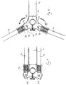
- a pair of lugs 76 extend in a downward sloping direction away from the sleeve portion 70 for one of the legs 16, and a further pair of lugs 76 slope in a downward direction away from the sleeve portion 70, in such a manner that the block 14 is symmetrical about the intended vertical bisecting plane which passes through the axis of the sleeve portion 70.
- Recesses 78 are formed in the flat end faces 20 of each lug 76, and these recesses 78 correspond to the recesses 36 in the block 14 of the Figure 1 construction.
- the pivot construction of the block 14 in the Figure 7 construction is the same in every respect to that shown in the Figure 1 construction, with the pivot pins 28 extending between the lugs 76. It will be appreciated in this respect that the block 14 in the Figure 7 construction is not pivoted relative to the crossbar 12 to obtain the storage condition. Rather, the legs 16 are pivoted into a position where they are parallel to and adjacent to the crossbar 12, and the tubes 18 are simply removed from the blocks 14.
- Figure 7 construction of the block 14 and the parts attached thereto is shown more clearly in Figures 8 and 9.
- Figure 8 shows how the block 14 is strengthened by means of webs 82 between the sleeve portion 70 and each lug 76. It will be appreciated that in Figures 8 and 9, only one of each pair of lugs 76 is shown, being the rearmost one of the pair viewing the block 14 in the direction of these Figures.
- each lug 76 on one side of the axis of the sleeve portion 70 is in an intended vertical plane and is enlarged so that it is generally semi-circular, with a series of recesses 78 spaced apart around its periphery to enable the associated leg 16 to be releasably secured in a plurality of positions ranging from upright to horizontal when the pivot assembly is in use.
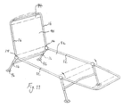
- Such a modified assembly is useful as a connection between a backrest 90 of a chair or bedchair and a seat part 92 thereof, as shown in Figure 11.
- the legs 16 which extend upwardly from these two blocks are constituted by the two arms of an inverted U-frame 94 constituting part of the back rest 90.
- the other leg 16 extends downwardly and outwardly towards the ground when the bedchair is in use.
- the legs 16 may be telescopically adjustable in length independently of one another and may have flanged feet 96.
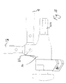
- the modified block 14 shown in Figures 12 to 14 is constructed for a rod support. Instead of a sleeve portion 70, it has a lug 100 which forms a tight fit within a tubular crossbar 12. Instead of a hole 72 for receiving a tube 18, it is formed with an upright lug 102. This extends in an intended upright direction at right angles to the lug 100. It may be generally U-shaped as viewed from above, as shown in Figure 14. A bank stick 104 is pivotally attached to the lug 102 in the same way as the leg 16 is attached to the pair of lugs 76.
- the lug 102 may have an external screw thread 106 formed around its outside which is engaged, when the rod support is in use by an internal screw thread 108 of a locking sleeve 110.
- the locking sleeve 110 when engaging the screw threads of the lug 102, encloses the sleeve 38, and the sleeve 110 has a substantially closed end 112 which forms a sliding fit with the bank stick 104.
- An O-ring, or split collar, 114 is positioned between the sleeve 110 and the bank stick 104 at the closed end 112, and abuts the upper or outer end of the sleeve 38 when the screw threading 106 and 108 are fully engaged, to fix the position of the bank stick 104 even more securely.
- the bank stick 104 can be readily brought parallel to and adjacent to the crossbar 12 firstly by unscrewing the sleeve 110 from the lug 102, lifting that sleeve 110, and then lifting the sleeve 38 so that the projection 40 is taken clear of the hole or recess 36.
- each pair of lugs 76 in this construction are formed on a separate block portion, and that these block portions are held together by means of a locking screw 120 which passes through the various block portions.
- an outer sleeve 110 could be provided to surround the sleeves 38 for each of the legs 16, as in the construction shown for the bank stick 104.
- numerous variations and modifications to the illustrated embodiments can be made without taking the resulting construction outside the scope of the present invention.
Landscapes
- Health & Medical Sciences (AREA)
- Dentistry (AREA)
- General Health & Medical Sciences (AREA)
- Special Chairs (AREA)
- Chairs Characterized By Structure (AREA)
- Ladders (AREA)
- Pivots And Pivotal Connections (AREA)
Applications Claiming Priority (2)
| Application Number | Priority Date | Filing Date | Title |
|---|---|---|---|
| GB9820296 | 1998-09-17 | ||
| GB9820296A GB9820296D0 (en) | 1998-09-17 | 1998-09-17 | Pivot assembly |
Publications (3)
| Publication Number | Publication Date |
|---|---|
| EP0987395A2 true EP0987395A2 (de) | 2000-03-22 |
| EP0987395A3 EP0987395A3 (de) | 2003-10-08 |
| EP0987395B1 EP0987395B1 (de) | 2006-11-02 |
Family
ID=10839043
Family Applications (1)
| Application Number | Title | Priority Date | Filing Date |
|---|---|---|---|
| EP19990306029 Expired - Lifetime EP0987395B1 (de) | 1998-09-17 | 1999-07-29 | Scharnieranordnung |
Country Status (3)
| Country | Link |
|---|---|
| EP (1) | EP0987395B1 (de) |
| DE (1) | DE69933829T2 (de) |
| GB (1) | GB9820296D0 (de) |
Family Cites Families (3)
| Publication number | Priority date | Publication date | Assignee | Title |
|---|---|---|---|---|
| US1809564A (en) * | 1926-08-16 | 1931-06-09 | Lyon Metal Products Inc | Folding table |
| US3026161A (en) * | 1958-09-25 | 1962-03-20 | Samuel R Mickelson | Leg locking device for folding tables |
| US3305204A (en) * | 1965-06-09 | 1967-02-21 | Douglas Godfrey | Pivotally mounted support means |
-
1998
- 1998-09-17 GB GB9820296A patent/GB9820296D0/en not_active Ceased
-
1999
- 1999-07-29 DE DE1999633829 patent/DE69933829T2/de not_active Expired - Fee Related
- 1999-07-29 EP EP19990306029 patent/EP0987395B1/de not_active Expired - Lifetime
Also Published As
| Publication number | Publication date |
|---|---|
| GB9820296D0 (en) | 1998-11-11 |
| DE69933829D1 (de) | 2006-12-14 |
| DE69933829T2 (de) | 2007-05-10 |
| EP0987395A3 (de) | 2003-10-08 |
| EP0987395B1 (de) | 2006-11-02 |
Similar Documents
| Publication | Publication Date | Title |
|---|---|---|
| EP0461838B1 (de) | Einstellbares Dreibeinstativ | |
| US6173660B1 (en) | Bench folding leg and brace structure | |
| US5826847A (en) | Telescoping pole with quick length adjustment | |
| US20140339859A1 (en) | Portable folding chair with adjustable legs | |
| US20080289675A1 (en) | Corner molding and stop assembly for collapsible shelter | |
| US11647827B2 (en) | Support pole system for supporting articles | |
| US11623113B2 (en) | Workout apparatus with telescoping legs | |
| US5277438A (en) | Collapsible recuperating walker | |
| CA2479340A1 (en) | Telescoping shoring post | |
| US6131749A (en) | Adjustable clothes rack | |
| US5505415A (en) | Tripod | |
| CA2671644A1 (en) | Adjustable leg | |
| JP3816526B2 (ja) | ジョイント機構 | |
| US20060032993A1 (en) | Tool used for removing and fitting a transmission gear box | |
| CN111186513A (zh) | 接收器适配器 | |
| ITPD970223A1 (it) | Stativo perfezionato per attrezzature foto-ottiche e cinematografiche | |
| US20050161560A1 (en) | Holder for cameras | |
| EP0987395A2 (de) | Scharnieranordnung | |
| US9968200B2 (en) | Portable seating apparatus and method | |
| EP2052601A2 (de) | Angelruten-Trägervorrichtung | |
| GB2178931A (en) | Supports | |
| US20040247377A1 (en) | Device for connecting legs to furnishing elements, and a furnishing element comprising that device | |
| US20100108850A1 (en) | Stand for supporting a tree | |
| WO2001009522A1 (en) | Length adjustment mechanism | |
| GB2177882A (en) | Supports |
Legal Events
| Date | Code | Title | Description |
|---|---|---|---|
| PUAI | Public reference made under article 153(3) epc to a published international application that has entered the european phase |
Free format text: ORIGINAL CODE: 0009012 |
|
| AK | Designated contracting states |
Kind code of ref document: A2 Designated state(s): AT BE CH CY DE DK ES FI FR GB GR IE IT LI LU MC NL PT SE |
|
| AX | Request for extension of the european patent |
Free format text: AL;LT;LV;MK;RO;SI |
|
| PUAL | Search report despatched |
Free format text: ORIGINAL CODE: 0009013 |
|
| AK | Designated contracting states |
Kind code of ref document: A3 Designated state(s): AT BE CH CY DE DK ES FI FR GB GR IE IT LI LU MC NL PT SE |
|
| AX | Request for extension of the european patent |
Extension state: AL LT LV MK RO SI |
|
| RIC1 | Information provided on ipc code assigned before grant |
Ipc: 7A 01K 97/10 B Ipc: 7A 47C 1/026 B Ipc: 7E 05D 11/10 A |
|
| 17P | Request for examination filed |
Effective date: 20040224 |
|
| AKX | Designation fees paid |
Designated state(s): BE DE FR GB IT NL |
|
| GRAP | Despatch of communication of intention to grant a patent |
Free format text: ORIGINAL CODE: EPIDOSNIGR1 |
|
| GRAS | Grant fee paid |
Free format text: ORIGINAL CODE: EPIDOSNIGR3 |
|
| GRAA | (expected) grant |
Free format text: ORIGINAL CODE: 0009210 |
|
| AK | Designated contracting states |
Kind code of ref document: B1 Designated state(s): BE DE FR GB IT NL |
|
| PG25 | Lapsed in a contracting state [announced via postgrant information from national office to epo] |
Ref country code: IT Free format text: LAPSE BECAUSE OF FAILURE TO SUBMIT A TRANSLATION OF THE DESCRIPTION OR TO PAY THE FEE WITHIN THE PRESCRIBED TIME-LIMIT;WARNING: LAPSES OF ITALIAN PATENTS WITH EFFECTIVE DATE BEFORE 2007 MAY HAVE OCCURRED AT ANY TIME BEFORE 2007. THE CORRECT EFFECTIVE DATE MAY BE DIFFERENT FROM THE ONE RECORDED. Effective date: 20061102 |
|
| REG | Reference to a national code |
Ref country code: GB Ref legal event code: FG4D |
|
| REF | Corresponds to: |
Ref document number: 69933829 Country of ref document: DE Date of ref document: 20061214 Kind code of ref document: P |
|
| ET | Fr: translation filed | ||
| PLBE | No opposition filed within time limit |
Free format text: ORIGINAL CODE: 0009261 |
|
| STAA | Information on the status of an ep patent application or granted ep patent |
Free format text: STATUS: NO OPPOSITION FILED WITHIN TIME LIMIT |
|
| 26N | No opposition filed |
Effective date: 20070803 |
|
| BERE | Be: lapsed |
Owner name: FOX DESIGN INTERNATIONAL LTD Effective date: 20070731 |
|
| NLV4 | Nl: lapsed or anulled due to non-payment of the annual fee |
Effective date: 20080201 |
|
| PG25 | Lapsed in a contracting state [announced via postgrant information from national office to epo] |
Ref country code: NL Free format text: LAPSE BECAUSE OF NON-PAYMENT OF DUE FEES Effective date: 20080201 Ref country code: DE Free format text: LAPSE BECAUSE OF NON-PAYMENT OF DUE FEES Effective date: 20080201 |
|
| REG | Reference to a national code |
Ref country code: FR Ref legal event code: ST Effective date: 20080331 |
|
| PG25 | Lapsed in a contracting state [announced via postgrant information from national office to epo] |
Ref country code: BE Free format text: LAPSE BECAUSE OF NON-PAYMENT OF DUE FEES Effective date: 20070731 |
|
| PG25 | Lapsed in a contracting state [announced via postgrant information from national office to epo] |
Ref country code: FR Free format text: LAPSE BECAUSE OF NON-PAYMENT OF DUE FEES Effective date: 20070731 |
|
| PGFP | Annual fee paid to national office [announced via postgrant information from national office to epo] |
Ref country code: GB Payment date: 20080731 Year of fee payment: 10 |
|
| GBPC | Gb: european patent ceased through non-payment of renewal fee |
Effective date: 20090729 |
|
| PG25 | Lapsed in a contracting state [announced via postgrant information from national office to epo] |
Ref country code: GB Free format text: LAPSE BECAUSE OF NON-PAYMENT OF DUE FEES Effective date: 20090729 |