EP0987439A2 - Elektrisch angetriebene Pumpe - Google Patents
Elektrisch angetriebene Pumpe Download PDFInfo
- Publication number
- EP0987439A2 EP0987439A2 EP99402208A EP99402208A EP0987439A2 EP 0987439 A2 EP0987439 A2 EP 0987439A2 EP 99402208 A EP99402208 A EP 99402208A EP 99402208 A EP99402208 A EP 99402208A EP 0987439 A2 EP0987439 A2 EP 0987439A2
- Authority
- EP
- European Patent Office
- Prior art keywords
- pump
- bracket
- groove
- tank cylinder
- intermediate plate
- Prior art date
- Legal status (The legal status is an assumption and is not a legal conclusion. Google has not performed a legal analysis and makes no representation as to the accuracy of the status listed.)
- Granted
Links
- 230000001629 suppression Effects 0.000 claims abstract description 98
- 239000012530 fluid Substances 0.000 claims abstract description 43
- 230000010349 pulsation Effects 0.000 claims description 17
- 238000007599 discharging Methods 0.000 claims description 12
- 239000000463 material Substances 0.000 claims description 8
- 229910052782 aluminium Inorganic materials 0.000 claims description 6
- XAGFODPZIPBFFR-UHFFFAOYSA-N aluminium Chemical compound [Al] XAGFODPZIPBFFR-UHFFFAOYSA-N 0.000 claims description 6
- 230000005540 biological transmission Effects 0.000 claims description 4
- 239000011162 core material Substances 0.000 description 9
- 238000000034 method Methods 0.000 description 8
- 238000006243 chemical reaction Methods 0.000 description 7
- 238000004804 winding Methods 0.000 description 6
- 230000008878 coupling Effects 0.000 description 5
- 238000010168 coupling process Methods 0.000 description 5
- 238000005859 coupling reaction Methods 0.000 description 5
- 238000009751 slip forming Methods 0.000 description 5
- 239000000956 alloy Substances 0.000 description 4
- 239000000945 filler Substances 0.000 description 4
- 230000008569 process Effects 0.000 description 4
- 229910000838 Al alloy Inorganic materials 0.000 description 3
- 229910045601 alloy Inorganic materials 0.000 description 3
- 238000000465 moulding Methods 0.000 description 3
- 238000003825 pressing Methods 0.000 description 3
- 239000004576 sand Substances 0.000 description 3
- 230000000694 effects Effects 0.000 description 2
- 230000005484 gravity Effects 0.000 description 2
- 230000000149 penetrating effect Effects 0.000 description 2
- 238000007789 sealing Methods 0.000 description 2
- 229910000975 Carbon steel Inorganic materials 0.000 description 1
- 230000002411 adverse Effects 0.000 description 1
- 239000007767 bonding agent Substances 0.000 description 1
- 230000008859 change Effects 0.000 description 1
- 239000011248 coating agent Substances 0.000 description 1
- 238000000576 coating method Methods 0.000 description 1
- 230000003247 decreasing effect Effects 0.000 description 1
- 230000006866 deterioration Effects 0.000 description 1
- 230000007613 environmental effect Effects 0.000 description 1
- 239000007789 gas Substances 0.000 description 1
- 238000009434 installation Methods 0.000 description 1
- 229910052751 metal Inorganic materials 0.000 description 1
- 239000002184 metal Substances 0.000 description 1
- 230000002250 progressing effect Effects 0.000 description 1
- 238000005086 pumping Methods 0.000 description 1
- 230000009467 reduction Effects 0.000 description 1
- 230000004044 response Effects 0.000 description 1
- 238000005728 strengthening Methods 0.000 description 1
- 229920003002 synthetic resin Polymers 0.000 description 1
- 239000000057 synthetic resin Substances 0.000 description 1
Images









Classifications
-
- F—MECHANICAL ENGINEERING; LIGHTING; HEATING; WEAPONS; BLASTING
- F04—POSITIVE - DISPLACEMENT MACHINES FOR LIQUIDS; PUMPS FOR LIQUIDS OR ELASTIC FLUIDS
- F04C—ROTARY-PISTON, OR OSCILLATING-PISTON, POSITIVE-DISPLACEMENT MACHINES FOR LIQUIDS; ROTARY-PISTON, OR OSCILLATING-PISTON, POSITIVE-DISPLACEMENT PUMPS
- F04C15/00—Component parts, details or accessories of machines, pumps or pumping installations, not provided for in groups F04C2/00 - F04C14/00
- F04C15/0042—Systems for the equilibration of forces acting on the machines or pump
- F04C15/0049—Equalization of pressure pulses
-
- F—MECHANICAL ENGINEERING; LIGHTING; HEATING; WEAPONS; BLASTING
- F01—MACHINES OR ENGINES IN GENERAL; ENGINE PLANTS IN GENERAL; STEAM ENGINES
- F01C—ROTARY-PISTON OR OSCILLATING-PISTON MACHINES OR ENGINES
- F01C21/00—Component parts, details or accessories not provided for in groups F01C1/00 - F01C20/00
- F01C21/10—Outer members for co-operation with rotary pistons; Casings
-
- F—MECHANICAL ENGINEERING; LIGHTING; HEATING; WEAPONS; BLASTING
- F04—POSITIVE - DISPLACEMENT MACHINES FOR LIQUIDS; PUMPS FOR LIQUIDS OR ELASTIC FLUIDS
- F04C—ROTARY-PISTON, OR OSCILLATING-PISTON, POSITIVE-DISPLACEMENT MACHINES FOR LIQUIDS; ROTARY-PISTON, OR OSCILLATING-PISTON, POSITIVE-DISPLACEMENT PUMPS
- F04C11/00—Combinations of two or more machines or pumps, each being of rotary-piston or oscillating-piston type; Pumping installations
-
- F—MECHANICAL ENGINEERING; LIGHTING; HEATING; WEAPONS; BLASTING
- F04—POSITIVE - DISPLACEMENT MACHINES FOR LIQUIDS; PUMPS FOR LIQUIDS OR ELASTIC FLUIDS
- F04C—ROTARY-PISTON, OR OSCILLATING-PISTON, POSITIVE-DISPLACEMENT MACHINES FOR LIQUIDS; ROTARY-PISTON, OR OSCILLATING-PISTON, POSITIVE-DISPLACEMENT PUMPS
- F04C15/00—Component parts, details or accessories of machines, pumps or pumping installations, not provided for in groups F04C2/00 - F04C14/00
- F04C15/0003—Sealing arrangements in rotary-piston machines or pumps
- F04C15/0034—Sealing arrangements in rotary-piston machines or pumps for other than the working fluid, i.e. the sealing arrangements are not between working chambers of the machine
Definitions
- the present invention relates to an electric pump apparatus, particularly concerns such an electric pump apparatus made to be a compact for vehicle-mount, which has a reservoir for storing operating fluid, the reservoir has a constitution in which an electric motor serving as a driving source is integrally attached on one side of a pump via a bracket, a opening-side-end portion of a tank cylinder is secured on the pump-supporting surface of the bracket so as to surround the pump.
- This type of the pumps are generally driven by engine as a driving source; however, since engine widely changes its rotational speed while traveling, engine is not quite appropriate for the driving source.
- engine is used as the driving source, various problems arise in which power-consumption for driving the pump causes an increase in fuel-consumption rate, and furthermore mounting position of the pump could be limited due to obtaining transmission from the engine.
- electric pump apparatuses which use an electric motor as a driving source that is driven by power supply from a car-mounted battery instead of the engine, have been replacing the engine-driven-pump apparatuses.
- electric vehicles have been developed in order to prevent environmental deterioration due to exhaust gases, because the EV use an electric motor for the driving source instead of engine.
- the EVs may be mounted with hydraulic-actuating devices, therefore electric pump apparatuses using electric motors as driving sources are inevitably applied with respect to generation sources of oil pressure for such hydraulic-actuating devices.
- Japanese Laid-Open Patent Application No. 10-82377 (1998) by the applicant of the present invention has disclosed an electric pump apparatus in which: a pump is supported on one side of a bracket with an electric motor being supported on the other side, and both of these are connected at the axal portion of the bracket while a bottomed-cylindrical tank cylinder being secured on the pump-supporting surface of the bracket so as to surround the pump, and thus a reservoir for storing operating fluid is constituted, furthermore, mountability onto vehicle is enhanced by integrating the reservoir and electric motor with the pump.
- securing of the tank cylinder is achieved by allowing a flange circumferentially provided on its opening-side-end portion to contact the supporting surface of the bracket and fastening them together with a supporting flange of the electric motor being contacted to the other surface of the bracket by a plurality of securing bolts placed along the circumferential direction.
- the problem with the electric pump apparatus is that the assembly including this securing process is very complex.
- tank cylinders In order to make it applicable to both types, two types of tank cylinders are prepared: one is for longitudinal application in which an oil filler port for operating fluid is opened on bottom surface that faces up when mounted, and the other is for transversal application in which similar oil filler port is opened on circumferential surface, and either of these types will be selected depending on the alignment type.
- the tank cylinder can not be removed solely, and thus the assembly including the installation of the electric motor has to started over.
- the above-mentioned tank cylinder is made out of a thin cylindrical body, therefore it tends to be damaged due to various reasons while in-use.
- a replacement of the tank cylinder is required due to such a damaged, a complex task including adjustments of assembly of the electric motor which needs to be removed together with the tank cylinder will also be required. Therefore, replacement on assembly basis including the pump and electric motor is conventionally conducted instead of on part basis; this causes an increase in costs required for the replacement.
- the pump in the electric pump apparatus constituted as described above is provided as a rotational volume type such as a gear pump or vane pump.
- a rotational volume type such as a gear pump or vane pump.
- a suppression chamber having the aforementioned inner volume is constructed inside a reservoir formed on the other side of the pump, and this suppression chamber is used as an accumulator by communicating it with the discharging side of the pump, and thus pressure fluid whose pulsations have been reduced while passing through the suppression chamber is sent out to the discharging side.
- the electric pump apparatus disclosed in Japanese Laid-Open Patent Application No.10-82377 has a constitution in which the driving electric motor and reservoir are integrally formed with the pump. Moreover, the apparatus also has a constitution in which the pulsations on the discharging side is reduced by having the suppression chamber as an integral part; thus, it is very easy for car application.
- the present invention has been devised to solve the above-mentioned problems, and one of the objectives of the present invention is to provide an electric pump apparatus integrally having a reservoir with a pump and electric motor, by adopting a supporting configuration in which a tank cylinder, which constitutes a reservoir for storing operating fluid, is solely detachably attached to a bracket for supporting the pump and electric motor; thereby simplifying its assembly, enabling for replacement of the tank cylinder alone.
- Another objective of the present invention is to provide a more compact electric pump apparatus by reducing its shaft direction dimension, with an effective arrangement of a suppression chamber for reducing pulsations.
- the electric pump apparatus of the present invention in which a reservoir is constituted by circumferentially providing a groove on the pump side end surface of a cylindrical bracket for supporting the pump and electric motor, and fitting an opening-side-end portion of a bottomed-cylindrical tank cylinder into the groove so as to surround the pump, is characterized in that the opening-side-end portion of the tank cylinder is fitted into the groove circumferentially provided to the pump side end surface, an anti-come-off ring is engaged with a side wall of the groove, and thus the tank cylinder is secured so as not to come off from the groove.
- the groove having a shape corresponding to the opening end of the tank cylinder is provided on one surface of the bracket to which the tank cylinder is secured for constituting the reservoir, the opening-side-end portion of the tank cylinder is fitted into the groove, and this fitting portion is engaged with the anti-come-off ring being engaged with the side wall of the groove so as to secure to the groove without coming off lose.
- This secured condition is easily cancelled without giving an adverse effect on the securing of the electric motor, by removing the anti-come-off ring, and pulling the opening-side-end portion of the tank cylinder out from the groove.
- another electric pump apparatus of the present invention is characterized in that the anti-come-off ring is a snap ring having a circular cross-section.
- the snap ring having a circular cross-section is used as the anti-come-off ring. Therefore, mounting of the anti-come-off ring in-between the groove provided in the bracket and the tank cylinder fitted into the groove can be easier.
- still another electric pump apparatus of the present invention is characterized in that the tank cylinder is provided with: a fitting portion which has a predetermined length from the opening edge of the tank cylinder with a thickness approximately equal to width of the groove; an inlet surface which is located at a position farther than the fitting portion from the opening edge and which faces the side wall of the groove with a gap into which the anti-come-off ring is allowed to be introduced when being fitted; a guide surface which is located between the inlet surface and fitting portion, which outwardly inclined toward the opening edge to introduce the anti-come-off ring along the inlet surface to an engaging position of the anti-come-off ring; and an engage surface which is continuously provided with the guide surface while having a curved surface and which comes contact with the anti-come-off ring being engaged at the engaging position.
- the inlet surface thinner than the fitting portion is made to be facing against the side wall of the groove with a predetermined gap. Therefore, the anti-come-off ring is easily introduced through this gap.
- the anti-come-off ring introduced as described above is further introduced into its engaging position along the inclined guide surface continuously provided with the guide surface, and the tank cylinder is firmly secured without coming off from the groove by contacting the anti-come-off ring to the curved engage surface continuously provided with the guide surface.
- still another electric pump apparatus of the present invention is characterized by comprising a biasing member which is intervened between the opening edge of the tank cylinder and the bottom surface of the groove, and which biases the tank cylinder to a direction away from the bottom surface, and thus the biasing member pushes the engage surface onto the anti-come-off ring.
- the biasing member intervened between the bottom surface of the groove provided to the bracket and the opening edge of the tank cylinder fitted in-to the groove, presses the tank cylinder in a direction away from the bottom surface of the groove, and thus the tank cylinder is held at secured state. Therefore, tilting of the tank cylinder within a mounting gap, caused by the effect of weight of operating fluid stored inside the tank cylinder, is prevented when used in the "transversally-aligned arrangement", for example.
- Still another electric pump of the present invention in which an input shaft (motor shaft) of the electric motor is attached to one side of the pump via the bracket, and the input shaft is connected together with a pump shaft (output shaft) of the pump, while the bracket is intervened between the pump and electric motor, and a suppression chamber is provided in a discharging path of the pump, and thus pulsations of pressurized fluid being discharged into the discharging path due to a transmitted force from the electric motor are reduced by the suppression chamber, is characterized in that the suppression chamber is provided to the bracket.
- a space constituted to the bracket provided for mounting the electric motor on the one side of the pump, excluding the connecting portion of the pump and electric motor, is utilized to constitute a suppression chamber for pulsation-reduction, and therefore a lengthwise space required for placing the suppression chamber on the other side of the pump is eliminated and thus the length in the shaft direction is shortened, as the result that the total size of the apparatus can be made more compact.
- Still another electric pump apparatus of the present invention is characterized in that a recess provided on the portion of the bracket opposing to the pump is sealed by the intermediate plate intervened between the bracket and pump.
- the recess is provided on the surface of the bracket opposing to the pump, and the suppression chamber is constituted so as to attain a necessary inner volume between the intermediate plate intervened between the pump and bracket and the inside of the recess.
- the intermediate plate is secured between the pump and bracket, and is having a strong structure to stand with a high pressure inside of the suppression chamber.
- still another electric pump apparatus of the present invention is characterized in that the intermediate plate is made of a high-tensile-strength aluminum material.
- the intermediate plate can be made comparatively lighter and thinner, therefore the total apparatus size in the shaft direction can be reduced, thus the entire apparatus can be much more compact.
- the suppression chamber is constituted by the recess provided to the portion of the bracket opposing to the pump and the intermediate plate, operable area of reaction force of the fluid pressure applied to the intermediate plate from the suppression chamber will be increased.
- the plate thickness has to be raised more than a predetermined thickness; however, this idea becomes inconsistent with the objective of achieving the compactness and light-weight for the apparatus.
- the intermediate plate is made of some sort of materials with high rigidity such as carbon steels, weight of the entire apparatus will increase.
- the present invention makes it possible to easily provide a compact and light-weight apparatus.
- still another electric pump apparatus of the present invention is characterized in that the suppression chamber is provided around the input shaft of the pump in a winding manner.
- flow path length of the pressurized fluid inside of the suppression chamber can be made longer than the ferential length of the suppression chamber, it is not necessary to provide the suppression chamber larger.
- the bracket in which the suppression chamber is provided can be smaller, and the pulsations can be effectively reduced. That is, in order to effectively reduce the pulsations of the pressurized fluid discharged from the pump, the longer the length of the flow path of the pressurized fluid inside the suppression chamber having the pressurized fluid storage with a predetermined volume, the better.
- the suppression chamber becomes bulky, with the result that the entire electric pump apparatus becomes large.
- the present invention makes it possible to lengthen the length of the flow path of the pressurized fluid inside of the suppression chamber without making the suppression chamber larger, and also to effectively reduce the pulsations.
- the winding of the suppression chamber makes it possible to increase strength of the suppression chamber portion in the bracket and consequently to further make the bracket much more compact.
- Still another electric pump apparatus of the present invention is characterized in that the suppression chamber is built inside the bracket.
- the suppression chamber can be constituted only with the bracket; therefore, as compared with a case in which the recess and intermediate plate constitute a suppression chamber, the number of parts can be reduced, and costs can be greatly reduced.
- the bracket is provided with an inlet hole for introducing the pressurized fluid discharged from the pump to the suppression chamber. Moreover, since acting area of the reaction force of the pressurized fluid applied to the pump from the suppression chamber is reduced as compared with a case in which the recess and intermediate plate constitute the suppression chamber, a necessary axial force of the securing bolt for securing the pump to the bracket can be reduced, with the result that the pump can be firmly secured by using smaller size securing bolts and the entire apparatus can be made much more compact, consequently.
- the other electric pump apparatus of the present invention is provided with a plurality of flanges which are respectively secured to the intermediate plate by securing screws (securing bolts); a synthetic-resin-made reservoir for surrounding the pump; a metal-made collar which is inserted through a perforation provided in each of the flanges; and a metal-made washer plate which is intervened between the collar and intermediate plate, and in which a plurality of the washer plates are integrally formed.
- the collar prevents the flange of the synthetic-resin-made reservoir from buckling, and also bucking of mounting surface of the intermediate plate can be effectively prevented by the washer plates; thus, it becomes possible to ensure a predetermined fastening axial force.
- the plurality of the washer plates are integrally formed, as compared with a case in which all the plurality of the washer plates are individually formed, the number of occurrences of dimensional errors in the washer plates can be reduced, the dimensional management of the washer plates can be easily made, the operability of the securing process of the reservoir can be improved, and it is possible to prevent the washer plates from being erroneously left unsecured at the time of the securing process.
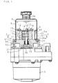
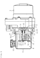
- FIG. 1 is an exploded side view showing an essential part of the first embodiment of an electric pump apparatus according to the present invention
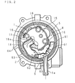
- FIG. 2 is a lateral cross-sectional view taken along line I-I of FIG. 1.
- a pump shaft 10 serving as an input shaft to the pump 1 and a motor shaft 30 serving as an output shaft of the electric motor :3 are co-axially aligned inside the bracket 2, and coupled together by a fit-in-type coupling 4.
- the driving force of the electric motor 3 taken out by the motor shaft 30 is transmitted to the pump shaft 10 through the coupling 4 so as to drive the pump 1.
- the pump 1 which is a known gear pump, is placed inside a cavity portion (gear chamber) with an elongated-circle cross-section, formed in a housing 11, so as to allow a driving gear 12 and driven gear 1:3 to engage with each other.
- Operating fluid inside of a suction chamber 18 (see FIG. 2) that is provided on one side of this engaging section, is pressurized while being transported in a sealed state between the respective gear teeth and inner circumferential surface of the cavity portion due to rotation of the gears 12 and 13, and discharged into an outlet chamber (not shown) provided on the other side of the engaging section.
- the driven gear 13 is shown as its one portion being overlapped by the driven gear 12 located on the front side of the drawing paper surface.
- the driving gear 12 and driven gear 13 are rotatably supported at their both ends by a pair of side plates 14 that are insertedly fitted into the cavity portion of the housing 11 from both sides of the gears, while being maintained in the above-mentioned engaging state.
- the pump shaft 10, fitted into the axial center of the driving gear 12, is allowed to penetrate through one of the side plates 14 toward the bracket 2 side, and connected to the motor shaft 30 of the electric motor 3 via the coupling 4. Therefore, with respect to the pumping movement by the pump 1 is carried out in which: rotation of the electric motor 3 is transmitted to the driving gear 12 through the motor shaft 30, coupling 4, and pump shaft 10 in that order, so that the driving gear 12 rotates within inner cavity portion of the housing 11, together with the driven gear 13 in mesh therewith.
- a tank cylinder 5 which consists of a thin plate member having a bottomed cylindrical shape, has its opening-side-end portion attached to the bracket 2 for supporting the above-mentioned pump 1 so as to surround the pump 1.
- a reservoir R for storing operating fluid is formed inside the tank cylinder 5.
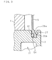
- FIG. 3 is an enlarged cross-sectional view showing proximity of the securing section of the tank cylinder 5 shown in FIG. 1.
- a groove 26a having a circular shape on its plan view that corresponds to the opening edge of the tank cylinder 5 is circumferentially provided so as to surround the pump 1.
- the above-mentioned tank cylinder 5 has its opening-side-end portion fitted into the groove 26a, with this fitting portion contacting a snap ring 27 engaging with outside side wall of the groove 26a so as be secured without coming off from the groove.
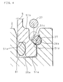
- FIG. 4 is an explanatory drawing showing a sequence of securing procedures of the tank cylinder 5 shown in FIG. 1.
- the tank cylinder 5 is provided with a fitting portion 51a, inlet surface 51b, guide surface 51c, and engage surface 51d.
- the fitting portion 51a is formed so as to have a thickness approximately equal to width of the groove 26a over an appropriate length from the opening edge of the tank cylinder 5.
- the inlet surface 51b has a thickness made to be thinner than the fitting portion 51a, and is formed on the side away from the opening edge.
- the guide surface 51c is located between the inlet surface 51b and fitting portion 51a so as to outwardly inclined toward the opening edge.
- the engage surface 51d has a curved surface continuously formed with the guide surface 51c.
- the tank cylinder 5 having the above-mentioned arrangement is supported with the fitting portion 51a on the opening edge side thereof being tightly fitted into the groove 26a, and secured in this state.
- the input surface 51b is allowed to face side wall of the groove 26a with a predetermined gap, and the guide surface 51c continuously formed and the engage surface 51d are continuously formed with a semi-circle engagement groove 26b formed on the side wall of the groove 26a so as to engage with the snap ring 27.
- the snap ring 27 is a sort of snap-on-type stop ring having a circular cross-section, cut at one place on its circumferential direction so as to have C-shape, and thus it is allowed to reduce in its diameter by closing the notched width.
- This snap ring 27 is introduced into the gap between the inlet surface 51b and side wall of the groove 26a while that diameter-reduced condition, and as indicated by a two-dot-chain line in FIG. 4, is further pushed into the inner side along the gap. This pushing can be securely carried out along the inlet surface 51b which faces in approximately parallel to the side wall of the groove 26a.
- the pushed-in snap ring 27 Upon reaching the guide surface 51c continuously formed with the inlet surface 51b, the pushed-in snap ring 27 is guided outwardly along the inclined slope of the guide surface 51c while expanding diameter by its own elasticity and allowed to engage the engagement groove 26b; thus, it comes into contact with the engage surface 51d formed as a curved surface as described above. Consequently, the tank cylinder 5 is secured with the fitting portion 51a fitted into the groove 26a being prevented from coming off by the snap ring 27.
- the engage surface 51d formed as the curved surface is contacting the snap ring 27 serving as an anti-come-off ring at one point on its curved surface. Therefore, a reaction force, indicated by an arrow in FIG. 4, is exerted on the snap ring 27 from the contact point outward in the radial direction, that is, in a direction so as to strengthen engagement to the engagement groove 26b. Consequently, the tank cylinder 5 is securely clamped in the above-mentioned secured state.
- a notched portion File On inner surface of the fitting portion 51a of the tank cylinder 5 is circumferentially provided with a notched portion File which has a rectangular cross-section.
- the opening edge of the tank cylinder 5 is tightly sealed with an 0-ring 81 intervened in the annular gap between the notched portion 51e and groove 26a. Therefore, the operating fluid stored inside the tank cylinder 5, that is, inside the reservoir R, is prevented from leaks.
- the tank cylinder 5 secured as described above is provided with, as illustrated in FIG. 2, a return opening which penetrates through the circumference wall of the tank cylinder 5 and which opens on the inner surface thereof at one position along the circumferential direction.
- This return opening is connected to an oil transporting end, not shown, through a return pipe 5a that is provided on the tank cylinder 5 in an outwardly protruding manner so that returned oil from the oil transporting end is returned to the reservoir R via the return pipe 5a.
- a flow-dividing plate 6 is attached to inside of the tank cylinder 5 so as to face the return opening at end of the return pipe 5a.
- This flow-dividing plate 6 is a plate member curved along the inner surface of the tank cylinder 5, and is provided with a flow-dividing protrusion 60 having a triangle cross-section that is protruded toward the return opening, in the approximately central portion.
- On one half portion of the flow-dividing plate 6 connecting to one side having this flow-dividing protrusion 60 a plurality of oil-returning perforations 61, which penetrate the circumference thereof, are formed, and on the other half portion of the flow-dividing plate 6 connecting to the other side, guide-out tubes 62 are formed on the end portion in parallel with each other.
- a suction tube 18a that communicates with a suction chamber 18 inside the housing 11.
- the suction tube 18a is a pipe or hose that radially outwardly protrude from the housing 11, and is curved along the inner surface of the tank cylinder 5.
- the tip portion of the guide-out tube 62 is inserted into the suction tube 18a that opens along the circumferential direction of the tank cylinder 5.
- the returned oil from the oil-feed destination through the return pipe 5a as described above collides with the flow-dividing protrusion 60 and is divided into two flows as indicated by arrows in FIG. 2.
- the returned oil that has been divided to one side (right side in FIG. 2) is returned to the tank cylinder 5 through the respective oil-returning perforations 61.
- the other portion of the returned oil that has been divided to the other side (left side in FIG.
- the operating fluid stored in the reservoir R is sucked into the suction chamber 18 through the suction tube 18a.
- one portion of the returned oil that has been returned through the return pipe 5a from the oil-feed destination is divided by the flow-dividing plate 6, and introduced into the suction chamber 18 through the guide-out tube 62 with predetermined pressure and velocity.
- the operating fluid, sucked into the suction chamber 18, is pressurized due to rotation of the driving gear 12 and driven gear 13 as described earlier, and discharged into an outlet chamber, not shown, that is formed on the other side of the suction chamber 18.
- a suppression chamber 21 having a predetermined inner volume is formed in the bracket 2 as an annular chamber that surrounds the connecting section between the pump shaft 10 and motor shaft 30.
- the outlet chamber of the pump 1 is allowed to communicate with the suppression chamber 21.
- an outlet base 64 is provided in a protruding manner as shown in FIG. 2, and a connecting port 63 that opens in the center of this outlet base 64 is allowed to communicate with the suppression chamber 21 inside the bracket 2.
- the discharged oil from the pump 1 is once introduced into the suppression chamber 21, and then sent out to the oil-feed destination, not shown, through the connecting port 63.
- the suppression chamber 21 is allowed to absorb pulsating components of the discharged oil that is introduced from the outlet chamber of the pump 1, thereby making it possible to reduce pulsations of the discharged oil from the outlet hole.
- the pulsating components of the discharged oil have a frequency, as its main component, that corresponds to a product between the number of rotations of the driving gear 12 and driven gear 13 serving as rotors and the numbers of teeth of the driving gear 12 and driven gear 13 that become the number of discharges per rotation.
- the inner volume of the suppression chamber 21 is properly determined so that it becomes possible to effectively absorb the above-mentioned pulsations.
- the electric pump apparatus shown in FIG. 1 is designed to be used for the "longitudinally-aligned arrangement" in which the shaft directions of the pump 1 and electric motor 3 are aligned longitudinally, and an oil filler port 53 for operating fluid is provided on the bottom surface of the tank cylinder 5 facing upward.
- the present invention is also applicable to an electric pump apparatus used for the "transversally-aligned arrangement” in which the shaft directions of the pump 1 and electric motor 3 are aligned transversally.
- FIG. 5 is an exploded side view showing an essential part of the second embodiment of an electric pump apparatus according to the present invention, which is used for the "transversally-aligned arrangement.”
- the oil filler port 53 for supplying operating fluid into the reservoir R is formed on circumferential surface of the tank cylinder 5 so as to face upward.
- the electric pump apparatus of the second embodiment is similar to the electric pump apparatus of the first embodiment shown in FIG. 1; therefore, the same reference numerals are used for similar members and the detailed description of the other arrangements and functions is omitted.
- illustrations of the return pipe 5a and flow-dividing plate 6 are omitted.
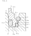
- FIG. 6 is an enlarged cross-sectional view showing proximity of securing section of the tank cylinder 5 in the "transversally-aligned arrangement" shown in FIG. 5.
- a notched portion 51f having a rectangular cross-section is also circumferentially provided on its outer surface, and an O-ring 82 is intervened in the annular gap between the notched portion 51f and groove 26a.
- This 0-ring 82 is, different from the sealing-use O-ring 81 intervened in the annular gap between the notched portion 51e and groove 26a, is intervened with a predetermined pressure being applied thereto between it and the bottom surface of the groove 26a.
- the O-ring 82 is pushing the fitting portion 51a of the opening end of the tank cylinder 5 to a direction away from the bottom surface of the groove 26a, pressing the engage surface 51d continuously formed with the fitting portion 51a against the snap ring 27 so that the clamping of the fitting portion 51a is strengthened.
- the above-mentioned strengthening of the clamping by intervention of the 0-ring 82 is effective even for the "longitudinally-aligned arrangement.” Therefore, the securing constitution shown in FIG. 6 may of course be applied to the electric pump apparatus for use in the "longitudinally-aligned arrangement" as shown in FIG. 1.
- other biasing members such as elastic rings having other forms and various types of springs, may be used so as to bias the opening end of the tank cylinder 5 in a direction away from the bottom surface of the groove 26a.
- the snap ring 27 having a circular cross-section is used as an anti-come-off ring for clamping the opening-side-end portion of the tank cylinder 5 that engages the groove 26a of the bracket 2 and is fitted into the groove 26a, so as not to come off; however, other type of the anti-come-off rings having different shapes may be used as long as it exerts the same functions.
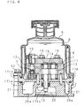
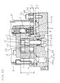
- FIG. 7 is an exploded side view showing an essential part of the third embodiment of an electric pump apparatus according to the present invention.
- the pump 1 of the third embodiment is sandwiched between an end plate 15 and intermediate plate 17 that are fastened together with a plurality of securing bolts 16 (only one of which is shown) aligned along the circumferential direction on both sides of the housing 11; thus, the both plates 15 and 17 prevent the side plate 14 from coming off.
- the above-mentioned intermediate plate 17 is, as illustrated in FIG. 7, a flat plate having a diameter sufficiently larger than the pump 1, and an opposing side surface to the pump 1 serves as a mounting base for the bracket 2 used for mounting the electric motor 3, and the other side surface, that is a surface on the same side as the pump 1 serves as a mounting base for the tank cylinder 5 that constitutes the reservoir.
- the tank cylinder 5 has its opening edge fitted into a faucet portion 171a that is circumferentially provided on the one-side-end surface (mounting side of the pump 1) of the intermediate plate 17, and attached so as to surround the pump 1.
- the bracket 2 is a cylindrical body with approximately the same diameter as the intermediate plate 17, and its opening edge on one side is fitted to a faucet portion 171b that is circumferentially provided on the other-end surface of the intermediate plate 17 so that it is attached co-axially with the intermediate plate 17.
- the tank cylinder 5 and bracket 2 located on both sides of the intermediate plate 17 are secured together in a sandwiching manner having the intermediate plate 17 in-between by fastened a plurality of securing bolts 52 (only one of which is shown), which are circumferentially placed on a securing flange 50 circumferentially provided on the former member, bolted through respective threaded holes formed at corresponding positions on outer circumferential portion of the bracket 2.
- the pump shaft 10 serving as an input shaft to the pump 1 is co-axially fitted into the driving gear 12 inside the housing 11, supported by the side plate 14 on both sides thereof, and allowed to protrude at axial center of the bracket 2 through a perforation penetrating through approximately center of the intermediate plate 17.
- the electric motor 3 is circumferentially provided with a securing flange on side to which a plurality of securing bolts :31 (only one of which is shown) are inserted in circumferential direction, and the securing bolts 31 are bolted through respective threaded holes formed on the-other-end surface of the bracket 2 so that the electric motor 3 is aligned coaxially with the bracket 2.
- the motor shaft 30 serving as the output shaft of the electric motor 3 is aligned co-axially with the pump shaft 10 at axial center of the bracket 2, and they are co-axially connected by the coupling 4.
- the outlet hole (not shown), for the pressurized fluid from inside of the gear chamber, is formed so as to penetrate through corresponding position of the intermediate plate 17 in the thickness direction.
- a groove 26a which has an annular shape surrounding the connecting portion between the pump shaft 10 and motor shaft 30, and which opens on the opposite side to the intermediate plate 17, is formed in the bracket 2 provided outside the intermediate plate 17.
- the outlet hole, which is formed so as to penetrate the intermediate plate 17, is allowed to open inside the suppression chamber 21.
- the suppression chamber 21 is connected to the oil-feed destination by an outlet tube, not shown, that is attached to circumference of the bracket 2.
- the discharged oil from the pump 1 is introduced into the suppression chamber 21 through the outlet hole that penetrates the intermediate plate 17, and then sent out to the oil-feed destination through the outlet tube.
- the suppression chamber 21 absorbs pulsating components of the discharged oil being introduced inside thereof through the outlet hole, and thus reduces pulsations of the discharged oil from the outlet tube.
- the inner volume of the suppression chamber 21 can be appropriately determined based upon main frequency component of the pulsations as described above.
- the suppression chamber 21, which reduces the pulsations as described above, is provided as an annular chamber surrounding the connecting portion of the pump shaft 10 and motor shaft 30 inside the bracket 2 which is provided so as to mount the driving-use electric motor 3 thereon.
- the bracket 2 has a required length in the shaft direction for enabling the above-mentioned connection.
- the suppression chamber 21 can be constructed without increasing its entire length in the shaft direction while maintaining the above-mentioned appropriate inner volume. Therefore, it is possible to provide an electric pump apparatus which is made to be much more compact.
- the suppression chamber 21 is to receive the discharged oil from the pump 1; however, this suppression chamber 21 is, as described above, constituted by sealing the opening side of the annular groove 26a formed in the bracket 2 with the intermediate plate 17.
- the intermediate plate 17 is firmly secured between the pump 1 and bracket 2 by a plurality of securing bolts 52 placed along the circumferential direction; thus, it is allowed to withstand high pressures inside the suppression chamber 21 with a sufficient allowance.
- a relief valve 7 is built in one position along the circumferential direction so as to release an excessive pressure inside the suppression chamber 21.
- This relief valve 7 is provided with a cylindrical spool holder 71, spool 72, and spring holder 73 inside a valve hole formed by penetrating the housing 11 including the end plate 15 in the shaft direction.
- the spool holder 71 is fitted into the opening on the side opposite to the intermediate plate 17, the spool 72 is slidably held at the axial center of the spool holder 71, and the spring holder 73 is attached to the opening on the end plate 15 side of the valve hole.
- a relief spring 74 is intervened between the opposing surfaces of the spring holder 73 and spool 72 so that tip of the spool 72 is pressed onto the intermediate plate 17 by a spring force of the relief spring 74.
- a connecting hole 75 which communicates with the suppression chamber 21 in the vicinity of pressing portion of the spool 72, is formed in the intermediate plate 17. Moreover, a relief hole 76 penetrates at halfway portion of the spool holder 71 in the radial direction, and the relief hole 76 is allowed to communicate with inside of the reservoir R constituted by the tank cylinder 5, through a communicating hole formed at the corresponding position of the housing 11.
- the opening end of the relief hole 76 to inside of the spool holder 71 is constituted so that the spool 72 held by the spool holder 71 is released when the spool 72 moves in a direction away from the intermediate plate 17 against spring force of the relief spring 74.
- the spool 72 is pressed toward opposite to the spring force of the relief spring 74 by an inner pressure of the suppression chamber 21 that is exerted on its tip through the connecting hole 75.
- the spool 72 is allowed to move in a leaving direction from the intermediate plate 17 when this pressing force exceeds the spring force of the relief spring 74, and this movement releases the relief hole 76 formed in the spool holder 71 so that the inner pressure of the suppression chamber 21 is released to the reservoir R through the connecting hole 75 and relief hole 76.
- the spring holder 73 with which the other end of the relief spring 74 elastically comes into contact is secured to the opening end on the end plate 15 side of the valve hole formed in the housing 11, and can be changed in its progressing length toward the valve hole by adjusting the thread.
- This change in length makes it possible to appropriately determined the spring force of the relief spring 74, that is, the relief pressure that is exerted against the spring force.
- the end of the spring holder 73 is protruded outside the end plate 15 as illustrated in FIG. 7; therefore, the adjusting operation on the thread for determining the relief pressure is easily carried out from outside the end plate 15.
- the other constitutions and functions of the electric pump apparatus of the third embodiment is similar to the first and second embodiments; therefore, the same reference numerals are used for similar members and the detailed description thereof is omitted.
- FIG. 8 is an exploded side view showing an essential part of the fourth embodiment of an electric pump apparatus according to the present invention, from which the section of an electric motor is omitted.
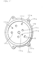
- FIGS. 9 through 11 are cross-sectional, plan and bottom views of the intermediate plate shown in FIG. 8 respectively.
- the intermediate plate 17 constituting the suppression chamber 21 together with the groove 26a of the bracket 2 is made of a high-tensile-strength aluminum material. Except this arrangement, the electric pump apparatus of the fourth embodiment is similar to the electric pump apparatus of the third embodiment shown in FIG. 7; therefore, the same reference numerals are used for similar members and the detailed description of the other arrangements and functions is omitted.
- the intermediate plate 17 of the electric pump apparatus of the third embodiment is made of an aluminum alloy standardized by Japanese Industrial Standard (JIS) H 2118, for example, type 12-1 or 12-2; however, an intermediate plate 17A of the fourth embodiment is made of a high-tensile-strength aluminum material standardized by JIS H 4000, such as, for example, any one of alloy numbers 2014, 2219, 2024, and 7075, or any one of alloy numbers 2014, 2024, and 7075 plus a core material as a laminated member, or any one of alloy numbers 2014, 2024, and 7075 plus a coating material as a laminated plate.
- JIS Japanese Industrial Standard
- the intermediate plate 17A is formed into a circular plate shape with a shaft hole 171c at the center thereof.
- a cylindrical faucet portion 171d to which the tank cylinder 5 is fitted is provided on one surface on the pump 1 side, and a cylindrical faucet portion 171e to which the bracket 2 is fitted is provided on the other surface on the bracket 2 side.
- an outlet hole 171f that communicates with the outlet chamber of the pump 1, the connecting hole 75, a pair of positioning holes 171g, and four perforations 171j through which the securing bolts 16 are inserted are respectively provided between the shaft hole 171c and faucet portion 171d.
- a plurality of flanges 171k (four in this case), each having a perforation 171h, are provided in a protruding manner along the outer circumference of the intermediate plate 17A, with predetermined intervals along the circumferential direction.
- the opening of the groove 26a is sealed so as to constitute the suppression chamber 21 together with a recess 20 so that the intermediate plate 17A, which has a comparatively large operable area of the fluid pressure reaction force, is made of a high-tensile-strength aluminum material; thus, it is allowed to withstand the fluid pressure reaction force even with a comparatively thin thickness. Therefore, it becomes possible to make the intermediate plate 17A much lighter with a comparatively thinner thickness, and consequently to reduce the dimension of the entire electric pump apparatus in the shaft direction so as to make the apparatus even smaller.
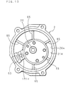
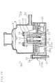
- FIG. 12 is a cross-sectional view showing a suppression chamber section in the fifth embodiment of an electric pump apparatus according to the present invention.
- FIG. 13 is a plan view showing a bracket in the fifth embodiment, and
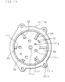
- FIG. 14 is a bottom view of an intermediate plate in the fifth embodiment.
- a plurality of first and second baffle plates 65 and 66 which extend from the bracket 2 and intermediate plate 17 or 17A toward the groove 26a, are alternately provided with predetermined intervals along the side wall of the groove 26a so that a suppression chamber 21A, which is allowed to wind in circumferential directions around the pump shaft 10 and motor shaft 30 by these baffle plates 65 and 66, is formed.
- the electric pump apparatus of the fifth embodiment is similar to the electric pump apparatus of the third embodiment shown in FIG. 7; therefore, the same reference numerals are used for similar members and the detailed description of the other arrangements and functions is omitted.
- the first and second baffle plates 65 and 66 are integrally formed with the bracket 2 and intermediate plate 17 or 17A, and when the intermediate plate 17 or 17A seals the groove 26a, predetermined gaps are formed between the first baffle plates 65 and bottom surface of the intermediate plate 17 or 17A, as well as between the second baffle plates 66 and surface of the recess of the bracket 2, as illustrated in FIG. 12. In other words, these gaps are formed as the suppression chamber 21A winding in circumferential directions.
- This suppression chamber 21A is provided with the outlet hole 171f, which penetrates through the intermediate plate 17 or 17A and communicates with the outlet chamber of the pump 1, at one end portion along its circumferential direction.
- the suppression chamber 21A is also provided with a connecting port 63 of the outlet tube at the other end portion along the circumferential direction.
- the suppression chamber 21A which has its lengthwise direction along the circumferential direction around the pump shaft 10 and motor shaft 30 so as to wind along the circumferential direction; thereby length of the flow path within the suppression chamber 21A for the pressurized fluid is lengthened as compared with that of the flow path within the suppression chamber 21 of the first embodiment without winding. Therefore, it is possible to preferably reduce the pulsations of the pressurized fluid without the need for increasing the size of the suppression chamber 21A not more than a predetermined size, and consequently to make the bracket 2, on which the suppression chamber 21A is provided, much more compact.
- the second baffle plates 66 used for winding the suppression chamber 21A may be formed on the bracket 2 together with the first baffle plates 65, although not shown, so as to allow the suppression chamber 21A to wind, instead of providing them on the intermediate plate 17 or 17A.
- the first baffle plates 65 are provided on one surface of a pair of circumferential surfaces that face each other in a protruding manner
- the second baffle plates 66 are provided on the other surface of the paired circumferential surfaces, and these first and second baffle plates 65 and 66 are placed alternately with a predetermined interval with each other.
- a gap is provided between the first baffle plate 65 and the one surface, as well as between the second baffle plate 66 and the other surface, so as to form a suppression chamber 21A winding along the circumferential direction.
- FIG. 15 is an exploded side view showing an essential part of the sixth embodiment of an electric pump apparatus according to the present invention, from which an electric motor section is omitted.
- FIG. 16 is a side view showing the tank cylinder shown in FIG. 15,
- FIG. 17 is a lateral cross-sectional view taken along line III-III of FIG. 16, and
- FIG. 18 is a lateral cross-sectional view taken along line II-II of FIG. 15.
- the electric pump apparatus of the sixth embodiment is provided with: a synthetic-resin-made tank cylinder 5 for surrounding the pump 1 having a plurality of flanges 54 which are secured onto the intermediate plate 17 or 17A by the securing bolts 52; metal-made collars 56 which are inserted through the perforations 55 formed in the flanges 54; and a plurality of (four in this case) of metal-made washer plates 57 which are intervened between the collars 56 and intermediate plate 17 or 17A.
- a plurality of the washer plates 57 are integrally formed.
- the electric pump apparatus of the sixth embodiment is similar to the electric pump apparatus of the third or fourth embodiment; therefore, the same reference numerals are used for similar members and the detailed description of the other arrangements and functions is omitted.
- FIG. 19 is a plan view showing the washer plates.
- the washer plates 57 is formed into a approximately arc shape, and one end portion and the other end portion in its lengthwise direction are made to be gradually wider than intermediate portion, and perforations 57a for securing the bolts 52 are provided in these one and other end portions.
- the collar 56 has a cylindrical shape in which one end portion has a tapered surface on its outer circumference and the other end portion has flange 56a.
- the collar 56 is inserted through a perforation 55 of the flange 54 from the cylindrical portion side of the tank cylinder 5 so as to allow the flange 56a to come in contact with mounting surface of the flange 54.
- a pair of recessed portions 58 are provided in the end surface on the flange 54 side of the tank cylinder 5 so that the recessed portions 58 are allowed to receive the washer plate 57.
- the washer plates 57 are placed into the respective paired recessed portions 58 of the tank cylinder 5, as well as inserting the collars 56 into the perforations 55 of the flanges 54.
- the tank cylinder 5 is directed to be contact with surface of the intermediate plate 17 or 17A on the pump 1 side, and the securing bolts 52 are inserted through the holes of the collars 56 and the perforations 171h of the intermediate plate 17 or 17A and bracket 2. Then, the securing bolts 52 are screwed into the threaded holes of the electric motor 3 side member so as to be clumped; thus the tank cylinder 5 is secured to the intermediate plate 17 or 17A, and the intermediate plate 17 or 17A and bracket 2 are secured to the electric motor 3 side member.
- the adjacent two washer plates 57 are integrally formed, probable dimensional errors of the washer plates 57 can be tremendously reduced as compared with having all washer plates formed as individual parts; thus, it is possible to easily manage the dimension of the washer plates 57.
- the number of the washer plates 57 can be reduced without decreasing the number of securing places, it is possible to improve operability for securing the of the tank cylinder, and also to prevent the washer plates 57 from being erroneously left unsecured during the securing process.
- the securing bolts 52 for securing the tank cylinder 5 may be arranged to be fastened to the threaded holes formed in the bracket 2 or intermediate plate 17 or 17A, instead of being fastened to the member on the electric motor 3 side.
- FIG. 20 is an exploded side view showing an essential part of the seventh embodiment of an electric pump apparatus according to the present invention, from which an electric motor section is omitted, and FIG. 21 is a lateral cross-sectional view taken along line IV-IV of FIG. 20.
- the pump 1 is secured to the bracket 2 by a plurality of the securing bolts 16, and the tank cylinder 5 is secured to the electric motor 3 side member by a plurality of the securing bolts 52. Except this arrangement, the electric pump apparatus of the seventh embodiment is similar to the electric pump apparatus of the third, fourth, or sixth embodiment; therefore, the same reference numerals are used for similar members and the detailed description of the other arrangements and functions is omitted.
- the bracket 2 is provided with four threaded holes 28 around the shaft holes with predetermined intervals with each other, and the intermediate plate 17 or 17A is provided with perforations corresponding to those threaded holes 28.
- Four securing bolts 16 for securing the pump 1 having the end plate 15 and housing 11 are inserted through the perforations, and the pump 1 is secured to the bracket 2 by fastening to the threaded holes 28.
- the tank cylinder 5 is provided with a plurality of flanges 54 having perforations 55 with a predetermined interval, as well as providing perforations corresponding to the perforations 55 to the intermediate plate 17 or 17A and bracket 2. Thereby, the tank cylinder 5 is secured to the intermediate plate 17 or 17A by inserting the four securing bolts 52 into these perforations and fastening to the electric motor 3 side member.
- the seventh embodiment is a constitution in which the most portion of the groove 26a formed on the pump 1 side surface of the bracket 2 is released so as to increase volume of the suppression chamber 21 or 21A; furthermore the securing bolts 16 for securing the pump 1 and the securing bolts 52 for securing the tank cylinder 5 are utilized so as to constitute the suppression chamber 21 or 21A together with the groove 26a. Therefore, in order to secure the intermediate plate 17 or 17A that has a greater operable area subjected to fluid pressure reaction force applied by the suppression chamber 21 or 21A, bolts with a comparatively small diameters can be used as the securing bolts 16 and 52.
- the intermediate plate 17 or 17A can be firmly secured without the need for increasing the number of the securing bolts 16 and 52 by using high-tensile-strength bolts.
- FIG. 22 is an enlarged cross-sectional view showing a securing section for securing a pump to a bracket in the eighth embodiment of an electric pump apparatus according to the present invention.
- a pair of first positioning holes lla are provided to the housing 11
- a pair of second positioning holes 171g corresponding to the positioning holes lla are provided to the intermediate plate 17 or 17A
- a pair of third positioning holes 22 are formed to the bracket 2.
- fitting depths L1 and L2 of the positioning pins 8 to the first and third positioning holes 11a and 22 are set within a range of 22% to 35% with respect to length L in the shaft direction of the housing 11.
- the electric pump apparatus of the eighth embodiment is similar to the electric pump apparatus of the third, fourth, sixth, or seventh embodiment shown in FIG. 7; therefore, the same reference numerals are used for similar members and the detailed description of the other arrangements and functions is omitted.
- the fitting depths L1 and L2 of the positioning pins 8 into the first and third positioning holes lla and 22 are set within a range of 7% to 11% with respect to the length L in the shaft direction of the housing 11; therefore, the housing 11 having the driving gear 12 and driven gear 13 inside becomes a vibration source, with its resonance point within a practical frequency band, thereby it tends to be causing noises.
- the fitting dimensions L1 and L2 of the positioning pins 8 of the eighth embodiment is set to be within the range of 22% to 35% as described above.
- the positioning pins 8 are fitted into the first through third positioning holes lla, 171g, and 22 so as to be lose-fitted.
- the positioning pins 8 of the eighth embodiment are fitted into the first through third positioning holes 11a, 171g, and 22 so as to be tight-fitted, thereby clamping mutual movements of the positioning pins 8, housing 11, intermediate plate 17 or 17A, and bracket 2.
- the positioning pins 8 which are placed in the vicinity of the vibration source, are utilized, and the fitting depths L1 and L2 of the positioning pins 8 to the first and third positioning holes 11a and 22 are set approximately three times longer, as compared with the conventional configuration. Therefore, it can shift the resonance point out of the practical frequency band, and consequently it can eliminate generation of noises due to the housing 11 by being a vibration source, without need for adding a particular arrangement. Moreover, since the positioning pins 8 are fitted into the first through third positioning holes lla, 171g, and 22 so as to be fastened therein; therefore it can further reduce generation of noises caused by the housing 11 being a vibration source.
- FIG. 23 is an exploded side view showing an essential part of the ninth embodiment of an electric pump apparatus according to the present invention, from which an electric motor section is omitted.
- the electric pump apparatus of the ninth embodiment instead of forming the suppression chamber 21 or 21A by the groove 26a and intermediate plate 17 or 17A, a built-in suppression chamber 21B having a approximately C-shape inside the bracket 2A is provided. Except this arrangement, the electric pump apparatus of the ninth embodiment is similar to the electric pump apparatus of the third embodiment shown in
- FIG. 7 therefore, the same reference numerals are used for similar members and the detailed description of the other arrangements and functions is omitted.
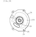
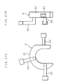
- FIGS. 24 through 26 are plan, cross-sectional, and bottom views of the bracket shown in FIG. 23, respectively; and FIGS. 27A and 27B are plan and side views showing a shell core for forming the suppression chamber shown in FIG. 23, respectively.
- the suppression chamber 21B is molded by using, for example, a gravity method by utilizing a shell core 9.
- This gravity method uses a pair of split dies (not shown) for molding the bracket 2A, and the shell core 9 corresponding to the suppression chamber 21B.
- This shell core 9 is made of sand and solidified by a synthetic-resin bonding agent, and it is provided with a core main body 91 having a approximately C-shape corresponding to the suppression chamber 21B, a pair of first arm portions 92 for molding two inlet holes 23, and a second arm portion 93 for molding the connecting port 63.
- This shell core 9 is placed inside the pair of split dies, and then a molten aluminum alloy material or molten high-tensile-strength aluminum material is poured into the split dies to mold the bracket 2A.
- a molten aluminum alloy material or molten high-tensile-strength aluminum material is poured into the split dies to mold the bracket 2A.
- the bracket 2A has been cooled off, the lump of sand is made to collapse, and the sand inside the bracket 2A is discharged outside through the inlet holes 2:3 and connecting port 63, the inside of the bracket 2A is shot-blasted, and then the bracket 2A itself is allowed to have a built-in suppression chamber 21B.
- the bracket 2A is provided with a pair of positioning holes 22 corresponding to the positioning holes 171g of the intermediate plate 17 or 17A, and a flange 25 having perforations 24 corresponding to the perforations 55 of the flange 54.
- the suppression chamber 21B can be constituted only with the bracket 2A without using the intermediate plate 17 or 17A as described in the third and fourth embodiments, as compared with the third and fourth embodiments in which the suppression chamber 21 or 21A is formed by the groove 26a and intermediate plate 17 or 17A, it becomes possible to reduce the number of parts, and consequently to greatly reduce costs.
- an inlet hole 23 for introducing pressurized fluid discharged from the pump 1 is provided on the pump 1 side surface of the bracket 2A, without allowing most of the suppression chamber 21 or 21A to be released as the third and fourth embodiments. Therefore, the operable area subjected to the fluid pressure reaction force applied from the suppression chamber 21B to the pump 1 can be reduced as compared with the third and fourth embodiments, and this makes it possible to reduce the axial force required for the securing bolts to secure the pump 1 to the bracket 2A, and also to firmly secure the pump 1 with small-size securing bolts; thus it becomes possible to make the entire electric pump apparatus compact.
- the suppression chamber 21, 21A, and 21B may be provided as, for example, an annular shape as the third embodiment, or may be provided as an approximately C-shape as the ninth embodiment.
- two or more suppression chambers 21, 21A, and 21B may be provided around the shaft hole 20 and 171c, and these chambers may be connected to each other by communicating paths. Therefore, the present invention does not particularly limit constitutions of the suppression chamber.
- the fourth through ninth embodiments are given as examples that are constituted based upon the third embodiment, the constitutions of these third through ninth embodiments may of course be applied to the electric pump apparatus having the mounting constitution of the tank cylinder 5 shown in the first and second embodiments.
- the above-mentioned embodiments have dealt with hydraulic-type electric pump apparatuses which are to be mounted on vehicles so as obtain operating fluid for hydraulic apparatuses such as power steering apparatuses and automatic transmission apparatuses; however, the present invention may of course be applied to electric pump apparatuses other than those used for vehicle-mount pumps, and may be further applied to electric pump apparatuses using fluid other than oil.
- the pump 1 is not intended to be limited to a gear pump as explained in the above-mentioned embodiments, and may be other pumps of the rotational volume type, such as vane pumps.
Landscapes
- Engineering & Computer Science (AREA)
- Mechanical Engineering (AREA)
- General Engineering & Computer Science (AREA)
- Details And Applications Of Rotary Liquid Pumps (AREA)
- Details Of Reciprocating Pumps (AREA)
- Reciprocating Pumps (AREA)
Priority Applications (1)
| Application Number | Priority Date | Filing Date | Title |
|---|---|---|---|
| EP03014492A EP1348869B1 (de) | 1998-09-18 | 1999-09-08 | Elektrisch angetriebene Pumpe |
Applications Claiming Priority (6)
| Application Number | Priority Date | Filing Date | Title |
|---|---|---|---|
| JP26505798 | 1998-09-18 | ||
| JP26505798 | 1998-09-18 | ||
| JP37471998 | 1998-12-28 | ||
| JP37471998A JP3773370B2 (ja) | 1998-09-18 | 1998-12-28 | 電動ポンプ |
| JP19675199A JP3734383B2 (ja) | 1999-07-09 | 1999-07-09 | 電動ポンプ |
| JP19675199 | 1999-07-09 |
Related Child Applications (1)
| Application Number | Title | Priority Date | Filing Date |
|---|---|---|---|
| EP03014492A Division EP1348869B1 (de) | 1998-09-18 | 1999-09-08 | Elektrisch angetriebene Pumpe |
Publications (3)
| Publication Number | Publication Date |
|---|---|
| EP0987439A2 true EP0987439A2 (de) | 2000-03-22 |
| EP0987439A3 EP0987439A3 (de) | 2002-05-15 |
| EP0987439B1 EP0987439B1 (de) | 2003-11-26 |
Family
ID=27327293
Family Applications (2)
| Application Number | Title | Priority Date | Filing Date |
|---|---|---|---|
| EP99402208A Expired - Lifetime EP0987439B1 (de) | 1998-09-18 | 1999-09-08 | Elektrisch angetriebene Pumpe |
| EP03014492A Expired - Lifetime EP1348869B1 (de) | 1998-09-18 | 1999-09-08 | Elektrisch angetriebene Pumpe |
Family Applications After (1)
| Application Number | Title | Priority Date | Filing Date |
|---|---|---|---|
| EP03014492A Expired - Lifetime EP1348869B1 (de) | 1998-09-18 | 1999-09-08 | Elektrisch angetriebene Pumpe |
Country Status (3)
| Country | Link |
|---|---|
| US (1) | US6287090B1 (de) |
| EP (2) | EP0987439B1 (de) |
| DE (2) | DE69936232T2 (de) |
Cited By (4)
| Publication number | Priority date | Publication date | Assignee | Title |
|---|---|---|---|---|
| WO2004072481A1 (de) * | 2003-02-17 | 2004-08-26 | Trw Automotive Gmbh | Hydraulikpumpe für ein servolenksystem |
| US20040202555A1 (en) * | 2003-04-11 | 2004-10-14 | Mitsubishi Denki Kabushiki Kaisha | Electro-hydraulic power steering apparatus |
| DE102004021885A1 (de) * | 2004-05-04 | 2005-12-01 | Zf Lenksysteme Gmbh | Rotations-Hydropumpe |
| EP3067528A1 (de) * | 2015-03-13 | 2016-09-14 | Inergy Automotive Systems Research (Société Anonyme) | Pumpe für eine flüssigkeit |
Families Citing this family (17)
| Publication number | Priority date | Publication date | Assignee | Title |
|---|---|---|---|---|
| DE19907556B4 (de) * | 1998-09-02 | 2007-10-25 | BSH Bosch und Siemens Hausgeräte GmbH | Flüssigkeitspumpe, insbesondere Laugenpumpe für Haushaltgeräte |
| US6874756B2 (en) | 2001-04-26 | 2005-04-05 | Swagelok Company | Snap assembly actuator housing and valve mounting bracket |
| USD486501S1 (en) | 2001-10-13 | 2004-02-10 | Swagelok Company | Combined snap assembly actuator housing and mounting bracket |
| USD500842S1 (en) | 2002-05-31 | 2005-01-11 | Swagelok Company | Manual valve actuator with cam |
| US20040022647A1 (en) * | 2002-08-05 | 2004-02-05 | Thompson Brett Franklin | Centrifugal pumps with internal cooling |
| USD476997S1 (en) | 2002-10-28 | 2003-07-08 | Jerry Tanner, Jr. | Electric oil pump for an engine |
| US20040193446A1 (en) * | 2003-03-27 | 2004-09-30 | Mayer Steven Lloyd | System and method for managing a patient treatment program including a prescribed drug regimen |
| FR2922274B1 (fr) * | 2007-10-12 | 2009-12-04 | Jtekt Hpi | Agencement de pompe hydraulique a engrenage externe et pourvue de moyens d'isolation acoustique |
| DE102015217214A1 (de) * | 2015-09-09 | 2017-03-09 | Continental Teves Ag & Co. Ohg | Befestigungsvorrichtung |
| GB201516861D0 (en) * | 2015-09-23 | 2015-11-04 | Parker Hannifin Mfg Uk Ltd | A motor pump assembly |
| CN107867323B (zh) * | 2016-09-28 | 2019-11-22 | 比亚迪股份有限公司 | 电机油泵总成、转向系统和车辆 |
| JP2018090071A (ja) * | 2016-12-02 | 2018-06-14 | ローベルト ボッシュ ゲゼルシャフト ミット ベシュレンクテル ハフツング | ブレーキ液圧制御装置、モータサイクル用ブレーキシステム、及び、ブレーキ液圧制御装置の製造方法 |
| DE102017215107A1 (de) | 2017-08-30 | 2019-02-28 | Volkswagen Aktiengesellschaft | Pumpe |
| DE102017127675B4 (de) * | 2017-11-23 | 2023-03-23 | HAWE Altenstadt Holding GmbH | Hydraulische Druckversorgungseinheit |
| JP6546984B1 (ja) * | 2017-12-27 | 2019-07-17 | Kyb株式会社 | 電動液圧アクチュエータ |
| DE102021210043A1 (de) * | 2021-09-10 | 2023-03-16 | Vitesco Technologies Germany Gmbh | Pumpe, insbesondere Getriebeölpumpe mit modularem Aufbau |
| US20260085682A1 (en) * | 2024-09-26 | 2026-03-26 | Caterpillar Inc. | Pump or motor mounting flange |
Family Cites Families (11)
| Publication number | Priority date | Publication date | Assignee | Title |
|---|---|---|---|---|
| US3434282A (en) * | 1967-03-14 | 1969-03-25 | Dura Corp | Safety backup system for power steering |
| US3871796A (en) * | 1973-11-15 | 1975-03-18 | Mccord Corp | Pump assembly |
| SE464655B (sv) * | 1986-01-31 | 1991-05-27 | Stal Refrigeration Ab | Rotationskompressor med tryckpulsdaempning |
| US5084162A (en) * | 1990-10-03 | 1992-01-28 | Allied-Signal Inc. | Push-on automotive filter |
| DE59201609D1 (de) * | 1991-12-17 | 1995-04-13 | Siemens Ag | Flüssigkeitsringpumpe. |
| DE4413515A1 (de) * | 1993-05-11 | 1994-11-17 | Barmag Luk Automobiltech | Hydraulikpumpe |
| FR2735534B1 (fr) | 1995-06-15 | 1997-08-29 | Hydroperfect Int | Ensemble moteur electrique et pompe hydraulique a grande compacite |
| US5853204A (en) * | 1995-07-17 | 1998-12-29 | Proprietary Technology, Inc. | Means of coupling non-threaded connections |
| FR2738302B1 (fr) | 1995-08-30 | 1997-10-10 | Hydroperfect Int | Groupe electro-hydraulique compact |
| DE19627405B4 (de) * | 1996-07-06 | 2004-10-21 | Zf Friedrichshafen Ag | Pumpenanordnung |
| JP3667034B2 (ja) | 1996-07-17 | 2005-07-06 | 光洋精工株式会社 | 電動ポンプ |
-
1999
- 1999-09-08 DE DE69936232T patent/DE69936232T2/de not_active Expired - Lifetime
- 1999-09-08 DE DE69913065T patent/DE69913065T2/de not_active Expired - Lifetime
- 1999-09-08 EP EP99402208A patent/EP0987439B1/de not_active Expired - Lifetime
- 1999-09-08 EP EP03014492A patent/EP1348869B1/de not_active Expired - Lifetime
- 1999-09-16 US US09/397,600 patent/US6287090B1/en not_active Expired - Lifetime
Cited By (10)
| Publication number | Priority date | Publication date | Assignee | Title |
|---|---|---|---|---|
| WO2004072481A1 (de) * | 2003-02-17 | 2004-08-26 | Trw Automotive Gmbh | Hydraulikpumpe für ein servolenksystem |
| US7488162B2 (en) | 2003-02-17 | 2009-02-10 | Trw Automotive Gmbh | Hydraulic pump for a power steering system |
| DE112004000205B4 (de) * | 2003-02-17 | 2013-04-11 | Trw Automotive Gmbh | Hydraulikpumpe für ein Servolenksystem |
| US20040202555A1 (en) * | 2003-04-11 | 2004-10-14 | Mitsubishi Denki Kabushiki Kaisha | Electro-hydraulic power steering apparatus |
| FR2853614A1 (fr) * | 2003-04-11 | 2004-10-15 | Mitsubishi Electric Corp | Dispositif de direction assistee electro-hydraulique |
| CN100341737C (zh) * | 2003-04-11 | 2007-10-10 | 三菱电机株式会社 | 电动油压式动力转向装置 |
| US7442013B2 (en) * | 2003-04-11 | 2008-10-28 | Mitsubishi Denki Kabushiki Kaisha | Electro-hydraulic power steering apparatus |
| DE102004021885A1 (de) * | 2004-05-04 | 2005-12-01 | Zf Lenksysteme Gmbh | Rotations-Hydropumpe |
| DE102004021885B4 (de) * | 2004-05-04 | 2009-10-01 | Zf Lenksysteme Gmbh | Rotations-Hydropumpe |
| EP3067528A1 (de) * | 2015-03-13 | 2016-09-14 | Inergy Automotive Systems Research (Société Anonyme) | Pumpe für eine flüssigkeit |
Also Published As
| Publication number | Publication date |
|---|---|
| EP1348869B1 (de) | 2007-05-30 |
| DE69936232T2 (de) | 2008-01-17 |
| DE69913065D1 (de) | 2004-01-08 |
| EP0987439B1 (de) | 2003-11-26 |
| DE69913065T2 (de) | 2004-09-09 |
| EP0987439A3 (de) | 2002-05-15 |
| EP1348869A1 (de) | 2003-10-01 |
| DE69936232D1 (de) | 2007-07-12 |
| US6287090B1 (en) | 2001-09-11 |
Similar Documents
| Publication | Publication Date | Title |
|---|---|---|
| EP1348869B1 (de) | Elektrisch angetriebene Pumpe | |
| JP3667034B2 (ja) | 電動ポンプ | |
| US10302185B2 (en) | Oil passage structure for power transmission device | |
| EP3309429B1 (de) | Öldurchgangsstruktur für kraftübertragungsvorrichtung | |
| US10190671B2 (en) | Vehicle drive device | |
| US20200208629A1 (en) | Pump assembly having two pumps provided in a single housing | |
| US20100242669A1 (en) | Vehicle drive apparatus | |
| JP4616879B2 (ja) | 軸受装置 | |
| KR100569494B1 (ko) | 가압상태의 액체를 수송하는 에너지 감쇄 장치, 이를포함하는 시스템 및 도관 내에서의 에너지 감쇄 방법 | |
| US7695250B2 (en) | Dual pump assembly | |
| CN116438390B (zh) | 差速器齿轮 | |
| JP3773370B2 (ja) | 電動ポンプ | |
| WO2008031012A2 (en) | Long life telescoping gear pumps and motors | |
| JPH094571A (ja) | 液圧ポンプ装置 | |
| JPS59180088A (ja) | ベ−ンポンプ | |
| JPH057577B2 (de) | ||
| US7699590B2 (en) | Oil pump and automatic transmission including the same | |
| JP4563880B2 (ja) | 並列複数気筒エンジン | |
| JP3734383B2 (ja) | 電動ポンプ | |
| EP1647713A2 (de) | Fluidpumpe mit Helmholtz-Resonator | |
| US20040136838A1 (en) | Electronic pressure relief valve for engine oil pump | |
| JP7463026B2 (ja) | ソレノイドバルブの固定構造 | |
| CN121778087A (zh) | P2构型的混合动力系统及摩托车 | |
| JP2000179466A (ja) | 回転式ポンプ及び回転式ポンプを備えたブレ―キ装置 | |
| JP2018063034A (ja) | バッフルプレートの取付け構造 |
Legal Events
| Date | Code | Title | Description |
|---|---|---|---|
| PUAI | Public reference made under article 153(3) epc to a published international application that has entered the european phase |
Free format text: ORIGINAL CODE: 0009012 |
|
| AK | Designated contracting states |
Kind code of ref document: A2 Designated state(s): AT BE CH CY DE DK ES FI FR GB GR IE IT LI LU MC NL PT SE |
|
| AX | Request for extension of the european patent |
Free format text: AL;LT;LV;MK;RO;SI |
|
| PUAL | Search report despatched |
Free format text: ORIGINAL CODE: 0009013 |
|
| AK | Designated contracting states |
Kind code of ref document: A3 Designated state(s): AT BE CH CY DE DK ES FI FR GB GR IE IT LI LU MC NL PT SE |
|
| AX | Request for extension of the european patent |
Free format text: AL;LT;LV;MK;RO;SI |
|
| 17P | Request for examination filed |
Effective date: 20020524 |
|
| 17Q | First examination report despatched |
Effective date: 20021015 |
|
| AKX | Designation fees paid |
Designated state(s): DE FR GB |
|
| GRAH | Despatch of communication of intention to grant a patent |
Free format text: ORIGINAL CODE: EPIDOS IGRA |
|
| GRAS | Grant fee paid |
Free format text: ORIGINAL CODE: EPIDOSNIGR3 |
|
| GRAA | (expected) grant |
Free format text: ORIGINAL CODE: 0009210 |
|
| AK | Designated contracting states |
Kind code of ref document: B1 Designated state(s): DE FR GB |
|
| REG | Reference to a national code |
Ref country code: GB Ref legal event code: FG4D |
|
| REF | Corresponds to: |
Ref document number: 69913065 Country of ref document: DE Date of ref document: 20040108 Kind code of ref document: P |
|
| REG | Reference to a national code |
Ref country code: IE Ref legal event code: FG4D |
|
| ET | Fr: translation filed | ||
| PLBE | No opposition filed within time limit |
Free format text: ORIGINAL CODE: 0009261 |
|
| STAA | Information on the status of an ep patent application or granted ep patent |
Free format text: STATUS: NO OPPOSITION FILED WITHIN TIME LIMIT |
|
| 26N | No opposition filed |
Effective date: 20040827 |
|
| REG | Reference to a national code |
Ref country code: IE Ref legal event code: MM4A |
|
| PGFP | Annual fee paid to national office [announced via postgrant information from national office to epo] |
Ref country code: GB Payment date: 20070905 Year of fee payment: 9 |
|
| GBPC | Gb: european patent ceased through non-payment of renewal fee |
Effective date: 20080908 |
|
| PG25 | Lapsed in a contracting state [announced via postgrant information from national office to epo] |
Ref country code: GB Free format text: LAPSE BECAUSE OF NON-PAYMENT OF DUE FEES Effective date: 20080908 |
|
| PGFP | Annual fee paid to national office [announced via postgrant information from national office to epo] |
Ref country code: DE Payment date: 20130904 Year of fee payment: 15 |
|
| PGFP | Annual fee paid to national office [announced via postgrant information from national office to epo] |
Ref country code: FR Payment date: 20130910 Year of fee payment: 15 |
|
| REG | Reference to a national code |
Ref country code: DE Ref legal event code: R119 Ref document number: 69913065 Country of ref document: DE |
|
| REG | Reference to a national code |
Ref country code: FR Ref legal event code: ST Effective date: 20150529 |
|
| PG25 | Lapsed in a contracting state [announced via postgrant information from national office to epo] |
Ref country code: DE Free format text: LAPSE BECAUSE OF NON-PAYMENT OF DUE FEES Effective date: 20150401 |
|
| PG25 | Lapsed in a contracting state [announced via postgrant information from national office to epo] |
Ref country code: FR Free format text: LAPSE BECAUSE OF NON-PAYMENT OF DUE FEES Effective date: 20140930 |