EP0987465B1 - Regulierbarer Dämpfer - Google Patents
Regulierbarer Dämpfer Download PDFInfo
- Publication number
- EP0987465B1 EP0987465B1 EP99115945A EP99115945A EP0987465B1 EP 0987465 B1 EP0987465 B1 EP 0987465B1 EP 99115945 A EP99115945 A EP 99115945A EP 99115945 A EP99115945 A EP 99115945A EP 0987465 B1 EP0987465 B1 EP 0987465B1
- Authority
- EP
- European Patent Office
- Prior art keywords
- damper
- piston
- cylindrical passageway
- housing
- monofilament
- Prior art date
- Legal status (The legal status is an assumption and is not a legal conclusion. Google has not performed a legal analysis and makes no representation as to the accuracy of the status listed.)
- Expired - Lifetime
Links
- 230000000295 complement effect Effects 0.000 claims description 3
- 230000003247 decreasing effect Effects 0.000 description 2
- 239000002184 metal Substances 0.000 description 1
- 230000002093 peripheral effect Effects 0.000 description 1
Images

Classifications
-
- F—MECHANICAL ENGINEERING; LIGHTING; HEATING; WEAPONS; BLASTING
- F16—ENGINEERING ELEMENTS AND UNITS; GENERAL MEASURES FOR PRODUCING AND MAINTAINING EFFECTIVE FUNCTIONING OF MACHINES OR INSTALLATIONS; THERMAL INSULATION IN GENERAL
- F16F—SPRINGS; SHOCK-ABSORBERS; MEANS FOR DAMPING VIBRATION
- F16F9/00—Springs, vibration-dampers, shock-absorbers, or similarly-constructed movement-dampers using a fluid or the equivalent as damping medium
- F16F9/02—Springs, vibration-dampers, shock-absorbers, or similarly-constructed movement-dampers using a fluid or the equivalent as damping medium using gas only or vacuum
- F16F9/0209—Telescopic
- F16F9/0218—Mono-tubular units
-
- F—MECHANICAL ENGINEERING; LIGHTING; HEATING; WEAPONS; BLASTING
- F16—ENGINEERING ELEMENTS AND UNITS; GENERAL MEASURES FOR PRODUCING AND MAINTAINING EFFECTIVE FUNCTIONING OF MACHINES OR INSTALLATIONS; THERMAL INSULATION IN GENERAL
- F16F—SPRINGS; SHOCK-ABSORBERS; MEANS FOR DAMPING VIBRATION
- F16F9/00—Springs, vibration-dampers, shock-absorbers, or similarly-constructed movement-dampers using a fluid or the equivalent as damping medium
- F16F9/32—Details
- F16F9/3207—Constructional features
-
- F—MECHANICAL ENGINEERING; LIGHTING; HEATING; WEAPONS; BLASTING
- F16—ENGINEERING ELEMENTS AND UNITS; GENERAL MEASURES FOR PRODUCING AND MAINTAINING EFFECTIVE FUNCTIONING OF MACHINES OR INSTALLATIONS; THERMAL INSULATION IN GENERAL
- F16F—SPRINGS; SHOCK-ABSORBERS; MEANS FOR DAMPING VIBRATION
- F16F9/00—Springs, vibration-dampers, shock-absorbers, or similarly-constructed movement-dampers using a fluid or the equivalent as damping medium
- F16F9/32—Details
- F16F9/54—Arrangements for attachment
Definitions
- This invention pertains to a damper, such as is used with a glove box of an automobile.
- the damper includes an adjustable clamp and further includes a damper housing forming a cylinder with an area of decreased internal diameter.
- the prior art designs have several disadvantages. Firstly, the prior art designs frequently require secondary fasteners to attach the damper to the panel. Secondly, the prior art designs have frequently utilized a monofilament element with loops formed at each end. Metal clasps are pinched onto the monofilament element at each end to form loops. One loop is attached to the piston and the other loop is attached to the glove box. However, this design would fail if the clasps became loose. Additionally, once the loops are created on the monofilament element, the monofilament element distance is set and cannot be changed. Thirdly, the prior art designs typically have an initial jump when the glove box is released.
- an air damper with a housing, a cap, discs, an integral plastic monofilament element/piston, and a spring.
- the housing forms a cylinder through which the piston travels and further includes an integral fastener with opposed scythe-like hook structures to allow the housing to be "rocked-in" the panel without the use of separate secondary fasteners.
- the piston and the monofilament element are molded as a single piece. This eliminates any need for a secondary monofilament element with loops and clasps which may fail.
- the open end of the molded monofilament element has molded annular rings which allow an adjustable fastener to be attached to the open end. This adjustable fastener allows the length at which the monofilament element/piston attaches to the glove box to be adjustable. Therefore, one molded monofilament element/piston can be adjusted to various lengths, as appropriate for the application.
- the diameter of the cylinder formed within the damper housing is decreased near the closed end of the housing to increase friction between the piston discs and the housing when the air damper is in a closed or nearly closed position. This additional friction eliminates the initial jump otherwise frequently associated with air dampers.
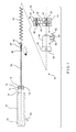
- FIG. 1 is an exploded view, partially in phantom, of the damper 10 of the present invention.
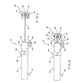
- Damper 10 includes cylindrical piston 12 with circular peripheral discs 14, 16 which engage cylinder passageway 18 of lower damper housing 20. Lip seal 13 extends from cylindrical piston 12. Piston 12 travels within cylinder passageway 18 as damper 10 is extended or retracted as shown in Figures 5 and 6, respectively.
- cylinder passageway 18 of lower damper housing 20 includes a lower portion 22 of reduced diameter, this reduction of diameter being exaggerated in Figure 1.
- piston 12 is molded integrally with monofilament element 24.
- the end 26 of monofilament element 24 opposite from piston 12 includes a series of enlarged molded annular rings 28 which form a male element 30 to attach to a corresponding female clamping element 32.
- Female clamping element 32 is a clamshell-type configuration with two clamping portions 33, 34 attached by a . living hinge 35, each clamping portion 33, 34 including a longitudinally divided complementary half 36, 37 of internally serrated aperture 38.
- Clamping portion 33 includes inwardly extending detent legs 39, 40 laterally adjacent to complementary half 36 of internally serrated aperture 38.
- Detent legs 39, 40 engage detent apertures 41, 42 of clamping portion 34 when clamping portions 33, 34 are in the closed position thereby forming internally serrated aperture 38 which engages male element 30.
- the outward side 43 of clamping portion 33 includes outwardly extending cylindrical detent element 45. Cylindrical detent element 45 is typically used to engage a cylindrical aperture of a structural device, such as the door of glovebox of an automobile (not shown) and may be replaced with many other fastening elements as would be known to a person skilled in the art.
- coil spring 44 is wrapped around monofilament element 24.
- a first end of coil spring 44 abuts piston 12 and a second end of coil spring 44 abuts upper damper housing 46 thereby urging piston 12 and monofilament element 24 toward a retracted position as illustrated in Figure 6.
- Upper damper housing 46 includes ring 48 on open end 50 thereof which snap fits onto lower damper housing 20. Upper damper housing 46 further includes closed end 52 with central aperture 54 through which monofilament element 24 reciprocatingly passes. Central aperture 54 is formed so that a longitudinal axis of damper 10 passes through central aperture 54.
- the cylindrical wall 56 of upper damper housing 46 further includes fastener 58 with opposed scythe-like hooks 60, 62.
- Lower damper housing 20 likewise includes fastener 63.
- the configuration of fastener 58 allows the damper 10 to be installed by a "rocking-in" motion with the subsequent alignment and engagement of fastener 63 without the necessity of secondary fasteners.
- the installer typically chooses a female clamping element 32 of the appropriate shape and size and attaches element 32 to male element 30 of monofilament element 24 at the position appropriate for the application.
- the installer then attaches fastener 58 to the appropriate door or panel (not shown) by a "rocking-in” motion and similarly attaches outwardly extending cylindrical detent element 45 to the appropriate door or panel (not shown).
- the choice of the dimensions of the particular elements and the adjustment thereof should provide for piston 12 to be urged into lower portion 22 of reduced diameter of cylinder passageway 18 when the associated door (not shown) is closed, and to allow piston 12 to traverse cylinder passageway 18 during the opening of the associated door.
- the sequence of steps can be varied according to the application and the preferences of the user.
Landscapes
- Engineering & Computer Science (AREA)
- General Engineering & Computer Science (AREA)
- Mechanical Engineering (AREA)
- Fluid-Damping Devices (AREA)
- Vehicle Step Arrangements And Article Storage (AREA)
Claims (14)
- Dämpfer (10), aufweisend:dadurch gekennzeichnet, dass das Schnurelement ein Monofilament-Element (24) ist und dass das erste Befestigungselement (30) am zweiten Befestigungselement (32) in einem Bereich von Positionen befestigbar ist und dadurch eine einstellbare Position des Eingriffselements mit Bezug auf das Monofilament-Element (24) liefert.ein Gehäuse (20, 46) mit einem darin gebildeten zylindrischen Durchgang (18), ferner eine Öffnung (54) im Gehäuse (20, 46) aufweisend, die zu dem zylindrischen Durchgang (18) führt;einen Kolben (12), der durch den zylindrischen Durchgang (18) verfährt; ein Schnurelement (24), das ein erste Ende (26) und ein zweites Ende aufweist, wobei das erste Ende (26) an einem ersten Befestigungselement (30) befestigt ist und das zweite Ende am Kolben (12) befestigt ist, wobei das Schnurelement (24) durch die Öffnung (54) hin und her verläuft;ein Eingriffselement mit einem zweiten Befestigungselement (32), wobei das zweite Befestigungselement (32) an dem ersten Befestigungselement (30) befestigt wird,
- Dämpfer nach Anspruch 1, wobei eines des ersten und zweiten Befestigungselements ein Steckelement (30) mit einer Vielzahl von ringförmigen Ringen (28) und das andere des ersten und zweiten Befestigungselements ein Aufnahmeelement (32) mit inneren Zacken ist, wobei die ringförmigen Ringe (28) mit den inneren Zacken in Eingriff gelangen.
- Dämpfer nach Anspruch 1 oder 2, wobei das Eingriffselement ferner ein drittes Befestigungselement (45) aufweist.
- Dämpfer nach mindestens einem der vorhergehenden Ansprüche, wobei das Eingriffselement zwei Klemmelemente (33, 34) aufweist, die gelenkig mit einander verbunden sind, und wobei jedes Klemmelement (33, 34) in Längsrichtung geteilte komplementäre Hälften (36, 37) einer Öffnung (38) aufweist, an der innere Zacken gebildet sind.
- Dämpfer nach mindestens einem der vorhergehenden Ansprüche, wobei das Monofilament-Element (24) integral mit dem Kolben (12) gebildet ist.
- Dämpfer nach mindestens einem der vorhergehenden Ansprüche, wobei das Monofilament-Element (24) und der Kolben (12) aus Kunststoff gebildet sind.
- Dämpfer nach mindestens einem der vorhergehenden Ansprüche, ferner eine Schraubenfeder (44) aufweisend, durch die das Monofilament-Element (24) verläuft.
- Dämpfer nach Anspruch 7, wobei die Schraubenfeder (44) ein erstes Ende und ein zweites Ende aufweist, wobei das erste Ende am Kolben (12) anliegt und das zweite Ende an einem Ende des zylindrischen Durchgangs (18) anliegt.
- Dämpfer nach Anspruch 8, wobei das Ende des zylindrischen Durchgangs (18), an dem das zweite Ende der Schraubenfeder anliegt, in der Nähe der Öffnung (54) ist.
- Dämpfer nach mindestens einem der vorhergehenden Ansprüche, wobei der Kolben (12) einen ersten Teil (22) des zylindrischen Durchgangs (18) durchläuft, wenn das Monofilament-Element (24) in einer relativ zurückgezogenen Position ist, und der Kolben (12) durch einen zweiten Teil des zylindrischen Durchgangs (18) verläuft, wenn das Monofilament-Element (24) in einer relativ ausgefahrenen Position ist, und wobei ein Durchmesser des ersten Teils (22) des zylindrischen Durchgangs gegenüber dem Durchmesser des zweiten Teils des zylindrischen Durchgangs (18) verringert ist.
- Dämpfer nach Anspruch 10, wobei der verringerte Durchmesser des ersten Teils (22) des zylindrischen Durchgangs (18) jeglichen anfänglichen Sprung des Dämpfers (10) minimiert.
- Dämpfer nach Anspruch 10 oder 11, wobei eine Längsachse des Gehäuses (20, 46) durch die Öffnung (54) verläuft und wobei die Öffnung (54) nahe zum zweiten Teil des zylindrischen Durchgangs (18) gebildet ist.
- Dämpfer nach mindestens einem der vorhergehenden Ansprüche, wobei das Gehäuse (20, 46) durch ein erstes Teil (20) und ein zweites Teil (46) gebildet ist, wobei das erste Teil mit dem zweiten Teil längs eines Umfangsabschnitts des Gehäuses verbunden ist.
- Dämpfer nach Anspruch 13, wobei das erste Teil (20) des Gehäuses mit dem zweiten Teil (46) des Gehäuses einrastend verbunden ist.
Applications Claiming Priority (2)
| Application Number | Priority Date | Filing Date | Title |
|---|---|---|---|
| US153276 | 1998-09-14 | ||
| US09/153,276 US6189662B1 (en) | 1998-09-14 | 1998-09-14 | Adjustable damper |
Publications (3)
| Publication Number | Publication Date |
|---|---|
| EP0987465A2 EP0987465A2 (de) | 2000-03-22 |
| EP0987465A3 EP0987465A3 (de) | 2002-09-11 |
| EP0987465B1 true EP0987465B1 (de) | 2005-01-12 |
Family
ID=22546500
Family Applications (1)
| Application Number | Title | Priority Date | Filing Date |
|---|---|---|---|
| EP99115945A Expired - Lifetime EP0987465B1 (de) | 1998-09-14 | 1999-08-13 | Regulierbarer Dämpfer |
Country Status (4)
| Country | Link |
|---|---|
| US (1) | US6189662B1 (de) |
| EP (1) | EP0987465B1 (de) |
| CA (1) | CA2281077C (de) |
| DE (1) | DE69923130T2 (de) |
Families Citing this family (9)
| Publication number | Priority date | Publication date | Assignee | Title |
|---|---|---|---|---|
| US6269919B1 (en) * | 1998-09-14 | 2001-08-07 | Illinois Tool Works Inc. | Plastic strand damper |
| JP3513650B2 (ja) * | 2000-01-07 | 2004-03-31 | 株式会社パイオラックス | エアダンパー |
| JP3994042B2 (ja) * | 2002-09-20 | 2007-10-17 | 株式会社パイオラックス | 紐式エアダンパー |
| US6945579B2 (en) * | 2003-06-27 | 2005-09-20 | Lear Corporation | Glove box door assembly |
| US7163248B2 (en) * | 2004-11-08 | 2007-01-16 | Lear Corporation | Automotive console with adjustable armrest |
| US7240941B2 (en) * | 2004-11-08 | 2007-07-10 | Lear Corporation | Vehicle storage assembly with adjustable door |
| US7314201B2 (en) * | 2005-01-07 | 2008-01-01 | La-Z-Boy Incorporated | Dampened retractable furniture cup holder |
| US9475421B2 (en) | 2013-10-23 | 2016-10-25 | Burton Technologies, Llc | Reflector damper bracket |
| EP4226056A4 (de) | 2020-10-05 | 2024-03-27 | ASYST Technologies L.P. | Einstellbarer gelenkarm |
Family Cites Families (16)
| Publication number | Priority date | Publication date | Assignee | Title |
|---|---|---|---|---|
| FR1120705A (fr) * | 1955-01-28 | 1956-07-11 | Amortisseur télescopique à résistance variable | |
| US3722920A (en) * | 1971-02-12 | 1973-03-27 | Reese Products | Hydraulic stabilizing device |
| DE3432739A1 (de) | 1984-09-06 | 1986-03-13 | Adam Opel AG, 6090 Rüsselsheim | Kraftfahrzeug |
| DE3445211A1 (de) | 1984-12-12 | 1986-06-12 | Ford-Werke AG, 5000 Köln | Verstauvorrichtung innerhalb von verkleidungen in kraftfahrzeugen |
| DE3611094A1 (de) | 1986-04-03 | 1987-10-08 | Opel Adam Ag | Aufbewahrungsfach |
| DE3628555A1 (de) | 1986-08-22 | 1988-02-25 | Daimler Benz Ag | Bremsvorrichtung fuer die oeffnungsbewegung von klappen und deckeln |
| DE3739921A1 (de) | 1987-11-25 | 1989-06-08 | Daimler Benz Ag | Handschuhkasten, insbesondere fuer kraftfahrzeuge |
| JPH077638Y2 (ja) * | 1988-10-24 | 1995-02-22 | 株式会社ニフコ | シリンダ型エアダンパー |
| JPH0463745A (ja) | 1990-07-04 | 1992-02-28 | Mazda Motor Corp | 車両用グローブボックス装置 |
| DE4109497C1 (de) | 1991-03-22 | 1992-08-13 | Mercedes-Benz Aktiengesellschaft, 7000 Stuttgart, De | |
| JP2785518B2 (ja) | 1991-06-24 | 1998-08-13 | 日産自動車株式会社 | グローブボックスダンパーの取付構造 |
| US5157806A (en) * | 1991-12-09 | 1992-10-27 | George Wartian | Door closing piston-cylinder assembly |
| US5197775A (en) | 1991-12-13 | 1993-03-30 | Ford Motor Company | Glove compartment |
| JP2557064Y2 (ja) | 1992-03-25 | 1997-12-08 | 株式会社パイオラックス | 収納箱等のダンパ−装置の構造 |
| US5289962A (en) | 1993-05-03 | 1994-03-01 | Chrysler Corporation | Cup holder |
| US5697477A (en) * | 1994-10-07 | 1997-12-16 | Nifco Inc. | Air damper |
-
1998
- 1998-09-14 US US09/153,276 patent/US6189662B1/en not_active Expired - Fee Related
-
1999
- 1999-08-13 DE DE69923130T patent/DE69923130T2/de not_active Expired - Fee Related
- 1999-08-13 EP EP99115945A patent/EP0987465B1/de not_active Expired - Lifetime
- 1999-08-24 CA CA002281077A patent/CA2281077C/en not_active Expired - Fee Related
Also Published As
| Publication number | Publication date |
|---|---|
| CA2281077C (en) | 2004-03-16 |
| CA2281077A1 (en) | 2000-03-14 |
| US6189662B1 (en) | 2001-02-20 |
| EP0987465A2 (de) | 2000-03-22 |
| EP0987465A3 (de) | 2002-09-11 |
| DE69923130D1 (de) | 2005-02-17 |
| DE69923130T2 (de) | 2005-06-02 |
Similar Documents
| Publication | Publication Date | Title |
|---|---|---|
| US3112547A (en) | Fastener | |
| EP0987465B1 (de) | Regulierbarer Dämpfer | |
| US5603532A (en) | Grab rings | |
| US5244324A (en) | Anchoring retainer for threaded fastener | |
| US6629335B1 (en) | Adjustable grip, clasping device | |
| US5906342A (en) | Holding device made of plastic | |
| US5197166A (en) | Cord closure | |
| US4110868A (en) | Air damper | |
| GB2372791B (en) | A member for removably closing a cylindrical opening | |
| US6305053B1 (en) | Cord lock | |
| US4174008A (en) | Access panel fastener retainer | |
| CA2307180C (en) | Plastic strand damper | |
| US4929006A (en) | Structure of sealing string | |
| US5165324A (en) | Piston-cylinder type air damper | |
| EP0537974B1 (de) | Seilklemme | |
| US5816458A (en) | Holders for arrangement of small goods | |
| US6367785B1 (en) | Air damper | |
| EP2707633A1 (de) | Rohrklemme | |
| US5653147A (en) | Expandable retainer for conduit end fitting | |
| US4644611A (en) | Snap hook | |
| US3590598A (en) | Finger ring with pivotally mounted size-adjusting member | |
| US5741007A (en) | Damper rotational latch | |
| US5538299A (en) | Housing and securing device | |
| MXPA99008351A (es) | Amortiguador ajustable | |
| WO1996010121B1 (en) | Housing and securing device |
Legal Events
| Date | Code | Title | Description |
|---|---|---|---|
| PUAI | Public reference made under article 153(3) epc to a published international application that has entered the european phase |
Free format text: ORIGINAL CODE: 0009012 |
|
| AK | Designated contracting states |
Kind code of ref document: A2 Designated state(s): AT BE CH CY DE DK ES FI FR GB GR IE IT LI LU MC NL PT SE |
|
| AX | Request for extension of the european patent |
Free format text: AL;LT;LV;MK;RO;SI |
|
| 17P | Request for examination filed |
Effective date: 20000822 |
|
| PUAL | Search report despatched |
Free format text: ORIGINAL CODE: 0009013 |
|
| AK | Designated contracting states |
Kind code of ref document: A3 Designated state(s): AT BE CH CY DE DK ES FI FR GB GR IE IT LI LU MC NL PT SE |
|
| AX | Request for extension of the european patent |
Free format text: AL;LT;LV;MK;RO;SI |
|
| AKX | Designation fees paid |
Designated state(s): DE FR IT |
|
| 17Q | First examination report despatched |
Effective date: 20030811 |
|
| GRAP | Despatch of communication of intention to grant a patent |
Free format text: ORIGINAL CODE: EPIDOSNIGR1 |
|
| GRAS | Grant fee paid |
Free format text: ORIGINAL CODE: EPIDOSNIGR3 |
|
| GRAA | (expected) grant |
Free format text: ORIGINAL CODE: 0009210 |
|
| AK | Designated contracting states |
Kind code of ref document: B1 Designated state(s): DE FR IT |
|
| REF | Corresponds to: |
Ref document number: 69923130 Country of ref document: DE Date of ref document: 20050217 Kind code of ref document: P |
|
| REG | Reference to a national code |
Ref country code: IE Ref legal event code: FG4D |
|
| PLBE | No opposition filed within time limit |
Free format text: ORIGINAL CODE: 0009261 |
|
| STAA | Information on the status of an ep patent application or granted ep patent |
Free format text: STATUS: NO OPPOSITION FILED WITHIN TIME LIMIT |
|
| ET | Fr: translation filed | ||
| 26N | No opposition filed |
Effective date: 20051013 |
|
| PGFP | Annual fee paid to national office [announced via postgrant information from national office to epo] |
Ref country code: DE Payment date: 20071001 Year of fee payment: 9 |
|
| PGFP | Annual fee paid to national office [announced via postgrant information from national office to epo] |
Ref country code: FR Payment date: 20070817 Year of fee payment: 9 |
|
| REG | Reference to a national code |
Ref country code: FR Ref legal event code: ST Effective date: 20090430 |
|
| PG25 | Lapsed in a contracting state [announced via postgrant information from national office to epo] |
Ref country code: FR Free format text: LAPSE BECAUSE OF NON-PAYMENT OF DUE FEES Effective date: 20080901 Ref country code: DE Free format text: LAPSE BECAUSE OF NON-PAYMENT OF DUE FEES Effective date: 20090303 |
|
| PGFP | Annual fee paid to national office [announced via postgrant information from national office to epo] |
Ref country code: IT Payment date: 20100825 Year of fee payment: 12 |
|
| PG25 | Lapsed in a contracting state [announced via postgrant information from national office to epo] |
Ref country code: IT Free format text: LAPSE BECAUSE OF NON-PAYMENT OF DUE FEES Effective date: 20110813 |