EP0987528A2 - Dispositif de traitement de l'information avec unité d'affichage couleur - Google Patents
Dispositif de traitement de l'information avec unité d'affichage couleur Download PDFInfo
- Publication number
- EP0987528A2 EP0987528A2 EP99304346A EP99304346A EP0987528A2 EP 0987528 A2 EP0987528 A2 EP 0987528A2 EP 99304346 A EP99304346 A EP 99304346A EP 99304346 A EP99304346 A EP 99304346A EP 0987528 A2 EP0987528 A2 EP 0987528A2
- Authority
- EP
- European Patent Office
- Prior art keywords
- color
- measuring
- color patch
- display
- measured
- Prior art date
- Legal status (The legal status is an assumption and is not a legal conclusion. Google has not performed a legal analysis and makes no representation as to the accuracy of the status listed.)
- Granted
Links
Images











Classifications
-
- G—PHYSICS
- G01—MEASURING; TESTING
- G01J—MEASUREMENT OF INTENSITY, VELOCITY, SPECTRAL CONTENT, POLARISATION, PHASE OR PULSE CHARACTERISTICS OF INFRARED, VISIBLE OR ULTRAVIOLET LIGHT; COLORIMETRY; RADIATION PYROMETRY
- G01J3/00—Spectrometry; Spectrophotometry; Monochromators; Measuring colours
- G01J3/46—Measurement of colour; Colour measuring devices, e.g. colorimeters
-
- G—PHYSICS
- G01—MEASURING; TESTING
- G01J—MEASUREMENT OF INTENSITY, VELOCITY, SPECTRAL CONTENT, POLARISATION, PHASE OR PULSE CHARACTERISTICS OF INFRARED, VISIBLE OR ULTRAVIOLET LIGHT; COLORIMETRY; RADIATION PYROMETRY
- G01J3/00—Spectrometry; Spectrophotometry; Monochromators; Measuring colours
- G01J3/46—Measurement of colour; Colour measuring devices, e.g. colorimeters
- G01J3/462—Computing operations in or between colour spaces; Colour management systems
-
- G—PHYSICS
- G01—MEASURING; TESTING
- G01J—MEASUREMENT OF INTENSITY, VELOCITY, SPECTRAL CONTENT, POLARISATION, PHASE OR PULSE CHARACTERISTICS OF INFRARED, VISIBLE OR ULTRAVIOLET LIGHT; COLORIMETRY; RADIATION PYROMETRY
- G01J3/00—Spectrometry; Spectrophotometry; Monochromators; Measuring colours
- G01J3/46—Measurement of colour; Colour measuring devices, e.g. colorimeters
- G01J3/52—Measurement of colour; Colour measuring devices, e.g. colorimeters using colour charts
- G01J3/524—Calibration of colorimeters
Definitions
- the present invention generally relates to information processing apparatuses, profile data creating methods, display units and storage mediums, and more particularly to an information processing apparatus, a profile data creating method and a display unit which are suited for generating a profile of the display unit, and to a computer-readable storage medium which stores a program suited for causing a computer to generate the profile of the display unit.
- a Color Management System is a technology for matching the manners in which the color is visible among the different input/output devices.
- CMS Color Management System
- the CMS it is possible to build a system which will not make a user feel uncomfortable or unnatural with respect to the image.
- ICM Image color Matching
- OS operating system
- Manufacturers of the input/output devices provide device profiles matching the ICM 1.0, the ColorSync 2.0 or the like with respect to the users, so that it is possible to obtain images which will not make the users feel uncomfortable or unnatural with respect to the images obtained among the different devices, such as the image displayed on the display device and the image printed by the printer.
- the device profiles matching the ICM 1.0, the ColorSync 2.0 or the like is in conformance with an International Color Consortium (ICC) profile proposed by the ICC.
- ICC International Color Consortium
- manufacturers of the input/output devices can make it possible for the users in the Windows environment and the users in the Macintosh environment to use the profiles in a similar manner and to obtain images which will not make the users feel uncomfortable or unnatural with respect to the images obtained among the different devices.
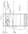
- FIG. 1 is a diagram for explaining the structure of the ICC profile.
- the necessary data are all described by tags.
- the ICC profile is made up of a profile header indicating information of the profile itself and information of a target input/output device, a tag table indicating kinds of information stored, and a tagged element data actually storing information.
- the profile header has a fixed length of 128 bytes.
- the tag table has a variable length of (4+12n) bytes with respect to n which indicates the number of tags, and includes an identifier, a storage address and a size.
- the tagged element data has a variable length, and contains information indicating the characteristics of the input/output device.
- FIG. 2 is a diagram showing a CIE XYZ uniform color space
- FIG. 3 is a diagram showing input/output characteristics of each of the colors read (R), green (G) and blue (B).
- the ordinate indicates a displayed luminance in arbitrary units
- the abscissa indicates an input voltage in arbitrary units.
- a display characteristic of a display unit which is one example of the input/output device from CIE XYZ values of the colors R, G and B shown in FIG. 2 when the colors R, G, and B respectively have maximum values Rmax, Gmax and Bmax (white Wmax), and from the input/output characteristics of the colors R, G and B shown in FIG. 3.
- the CIE XYZ values of the colors R, G and B shown in FIG. 2 are called a color reproduction range CR related to colors which can be discriminated by the human eye, and the input/output characteristics of the colors R, G and B shown in FIG. 3 are called ⁇ -characteristics.
- the CIE XYZ values of the colors R, G and B are stored in rXYZ, gXYZ and bXYZ tags of the ICC profile for the display unit, as information of the color reproduction range CR.
- input/output point values of the colors R, G and B are stored in rTRC, gTRC and bTRC tags of the ICC profile as the ⁇ -characteristics.
- a ⁇ -coefficient of the color is 1.0 when the number of points within the tag is 0, and the value of the ⁇ -coefficient itself is stored when the number of points is 1.
- the same number of input/output point values are stored in the ICC profile.
- the CIE XYZ value when the white has the maximum value Wmax is stored in a wtpt tag as standard white information of the display unit.
- Each of the tags described above is stored in the ICC profile shown in FIG. 1 as the tag element data.
- the 7 kinds of information described above are generally stored in the ICC profile of the display unit.
- the 7 kinds of information can be obtained by displaying color data on the display unit and measuring the displayed luminance and the CIE XYZ values by a color measuring device such as a spectral radiance measuring device.
- a power control is carried out to suppress the power consumption.
- an applying voltage applied to the PDP is reduced in a case where the power consumption is large such as when making a display which includes a large amount of white, and the applying voltage applied to the PDP is increased in a case where the power consumption is small such as when making a display which includes a large amount of dark colors such as gray and blue, so as to control the voltage applied to the PDP so that dark colors are displayed more brightly.
- measured results may indicate that the displayed luminance of blue is brighter than the displayed luminance of white.
- FIGS. 4 and 5 are diagrams showing measured results of actual displays on the display unit.
- FIG. 4 shows the measured results of the display unit which controls the applying voltage
- FIG. 5 shows the measured results of the display unit which does not control the applying voltage. More particularly, FIG. 4 shows the measured result of the PDP, and FIG. 5 shows the measured results of a CRT.
- the color reproduction range information and the standard white information are used on the precondition that the additive mixture of color stimuli stands. For this reason, there was a problem in that it is impossible to create the profile of the display unit from the measured results shown in FIG. 4 in which the additive mixture of color stimuli does not stand.
- the color reproduction range information and the standard white information must be measured under the same conditions, but in the display unit which carries out the power control described above, the applying voltage is freely controlled, for example, thereby changing the conditions such as the applying voltage depending on the displayed color. Because the measurements are not made under the same conditions when the power control is carried out, it is impossible to create the profile of the display unit from the measured results.
- a slight light emission may occur even when displaying black, due to the structure of the PDP.
- This slight light emission is sometimes referred to as a back light emission which causes considerably errors when creating the profile.
- Another and more specific object of the present invention is to provide an information processing apparatus, profile data creating method, display unit and storage medium, which enable a profile of the display unit to be created from measured results of the display made on the display unit, even in the case of a display unit which carries out a power control or the like and the same measuring conditions cannot be set by a user.
- Still another object of the present invention is to provide an information processing apparatus comprising a color display simultaneously displaying a reference color patch and at least one measuring color patch which is to be measured. According to the information processing apparatus of the present invention, it is possible to create the profile of a display unit from the measured results of the colors of the color patches displayed on the display unit, even in the case of the display unit which carries out a power control or the like and the same measuring conditions cannot be set by a user.
- a further object of the present invention is to provide a computer-readable storage medium which stores a program for causing a computer to display an image, comprising color display means for causing the computer to simultaneously display on a display unit a reference color patch and at least one measuring color patch which is to be measured.
- the storage medium of the present invention it is possible to create the profile of the display unit from the measured results of the colors of the color patches displayed on the display unit, even in the case of the display unit which carries out a power control or the like and the same measuring conditions cannot be set by a user.
- Another object of the present invention is to provide a display unit comprising a display screen, wherein the display screen displays a reference color patch which is used as a reference color, and at least one measuring color patch of a color different from that of the reference color patch.
- the display unit of the present invention it is possible to create the profile of the display unit from the measured results of the colors of the color patches displayed on the display unit, even in the case of the display unit which carries out a power control or the like and the same measuring conditions cannot be set by a user.
- Still another object of the present invention is to provide a profile data creating method for creating a profile data which is used to correct a display characteristic of a display unit corresponding to an input color signal, comprising a displaying step displaying, on a screen of the display unit, a reference color patch which is used as a reference color, and a measuring color patch of a color different from that of the reference color patch, a calculating step calculating a ratio of a measured value of the reference color patch and a measured value of the measured color patch which are measured from the screen, and a creating step creating a profile data based on the calculated ratio of the measured values.
- the profile data creating method of the present invention it is possible to create the profile of the display unit from the measured results of the color patches displayed on the display unit, even in the case of the display unit which carries out a power control or the like and the same measuring conditions cannot be set by a user.
- a further object of the present invention is to provide a profile data creating method for creating a profile data which is used to correct a display characteristic of a display unit corresponding to an input color signal, comprising a calculating step calculating relative values of a measured value of a reference color patch which is used as a reference color, and a measured value of a measuring color patch of a color different from that of the reference color patch, and a creating step creating a profile data based on the calculated relative values.
- the profile data creating method of the present invention it is possible to create the profile of the display unit from the measured results of the color patches displayed on the display unit, even in the case of the display unit which carries out a power control or the like and the same measuring conditions cannot be set by a user.
- a viewed color is compared with a reference color so as to recognize the tone of color of the viewed color.
- relative values with respect to the standard white are stored in the profile, by using the standard white as a reference.
- the reference color is not limited to a specific color, however, it is desirable that the reference color is white which has a maximum luminance for each of the primary colors R, G and B.
- FIG. 6 is a perspective view showing a first embodiment of an information processing apparatus according to the present invention.
- This embodiment of the information processing apparatus simultaneously displays a reference color patch and at least one measuring color which is to be measured on an embodiment of a display unit according to the present invention, based on a program which is stored in a first embodiment of a storage medium according to the present invention.
- a computer system 100 shown in FIG. 6 is formed by a general computer system such as a personal computer.
- the computer system 100 generally includes a main body part 101 which includes a CPU, a disk drive and the like, a display unit 102 which displays an image on a display screen 102a in response to an instruction from the main body part 101, a keyboard 103 which is used to input various kinds of information to the computer system 100, a mouse 104 which is used to specify an arbitrary position on the display screen 102a, a modem 105 which is used to make access to an external database or the like and to download a program or the like stored in another computer system, and a color measuring device 115.
- the color measuring device 115 has a known construction for measuring a color displayed at various parts on the display screen 102a, and is movable vertically and horizontally by a driving means.
- a program which is stored in a portable recording medium such as a disk 110 or is downloaded from a recording medium 106 of another computer system by use of a communication unit such as the modem 105, is input to and is compiled in the computer system 100.
- This program includes a program for causing the CPU of the computer system 100 to carry out a process of simultaneously displaying a reference color patch and at least one measuring color which is to be measured on the display unit 102.
- This embodiment of the storage medium is formed by a recording medium such as the disk 110 which stores the program described above.
- the recording medium is of course not limited to a portable or removable recording medium such as IC card memories, floppy disks, magneto-optical disks, CD-ROMs and various semiconductor memory devices, and also includes recording mediums which are accessible by a computer system which is coupled via a communication means or a communication unit such as the modem and LAN.
- FIG. 7 is a system block diagram showing the construction of an important part within the main body part 101 of the computer system 100.
- the main body part 101 generally includes a CPU 201, a memory part 202 including a RAM, ROM or the like, a disk drive 203 for the disk 110, and a hard disk drive 204 which are coupled via a bus 200.
- the display unit 102, the color measuring device 115 and the like are coupled to the bus 200.
- the construction of the computer system 100 is not limited to that shown in FIGS. 6 and 7, and various known constructions may be used in place thereof.
- FIG. 8 is a flow chart for explaining the operation of the CPU 201 in the first embodiment.
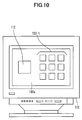
- a step S1 simultaneously displays a reference color patch and at least one measuring color which is to be measured on the display screen 102a of the display unit 102.
- the reference color patch and a plurality of measuring colors are displayed simultaneously.
- a step S2 measures the reference color displayed on the display screen 102a by use of the color measuring device 115, and stores a measured value in the memory part 202, for example.
- a step S3 measures the measuring color displayed on the display screen 102a by use of the color measuring device 115, and stores a measured value in the memory part 202, for example.
- a step S4 decides whether or not all of the measuring colors displayed on the display screen 102a are measured. The process returns to the step S3 if the decision result in the step S4 is NO. On the other hand, the process ends if the decision result in the step S4 is YES.
- the steps S2 and S3 measure the reference color white and the 9 kinds of measuring color red, so as to obtain a display characteristic of the display unit 102 for the color red.
- the steps S2 and S3 measure the reference color white and the 9 kinds of measuring color green, so as to obtain a display characteristic of the display unit 102 for the color green.
- the display unit 102 is a color display unit, and colors are used for the measuring colors.
- gray for example, may be used as the measuring color in the case of a monochrome display unit.
- the monochrome display unit it is possible to obtain a display characteristic of the monochrome display unit by displaying and measuring the reference color white and a plurality of gray having different tones.
- the display unit 102 is a color display unit
- the steps S2 and S3 measure the reference color white and the 9 kinds of measuring colors which are red, green, blue and predetermined color, so as to obtain the display characteristic of the display unit 102.
- measured results of the reference color obtained for the two display units can be compared.
- This embodiment of the information processing apparatus simultaneously displays a reference color and at least one measuring color which is to be measured on the display unit, based on a program which is stored in a second embodiment of the storage medium according to the present invention.
- the construction of this embodiment of the information processing apparatus may be the same as that of the first embodiment described above, and an illustration and description thereof will be omitted.
- FIG. 12 is a flow chart for explaining the operation of the CPU 201 in the second embodiment.
- steps which are the same as those corresponding steps in FIG. 8 are designated by the same reference numerals, and a description thereof will be omitted.
- This embodiment differs from the first embodiment described above, in that a step S5 is provided between the steps S3 and S4.
- the step S5 calculates a ratio of each measuring color which is measured with respect to the reference color, and stores each calculated ratio in the memory part 202, for example. In this embodiment, only the ratio of each measuring color which is measured with respect to the reference color is calculated and stored, and not the measured value of the color patch, such as the CIE XYZ value.
- the display characteristic of the display unit 102 is obtained from the calculated ratios.
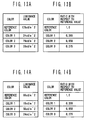
- FIGS. 13A, 13B, 14A and 14B are diagrams for explaining the ratio of each measuring color with respect to the reference color obtained in this embodiment, and show experimental data obtained by displaying all colors in one operation on the screen of the display unit as in the case shown in FIG. 11, for example.
- FIG. 13A shows each of the measured colors, and measured values thereof, that is, luminance values, for a first display unit.
- FIG. 13B shows each of the measured colors, and ratios of values which are obtained by normalizing luminance values of the measured colors by a reference value which is the measured result of the reference color, with respect to the reference value.
- FIG. 14A shows each of the measured colors, and measured values thereof, that is, luminance values, for a second display unit which is different from the first display unit.
- FIG. 14B shows each of the measured colors, and ratios of values which are obtained by normalizing luminance values of the measured colors by a reference value which is the measured result of the reference color, with respect to the reference value.
- the brightness of the displayed colors are completely different between the first display unit and the second display unit, due to the different type of display unit or the different display format used, and the measured values of each of the colors are completely different between the first and second display units.
- the ratios of the values which are obtained by normalizing the luminance values of the measured colors by the reference value which is the measured result of the reference color, with respect to the reference value are calculated as in this embodiment, it may be seen that the first and second display units show the same values. Accordingly, the first display unit having the values shown in FIGS. 13A and 13B and the second display unit having the values shown in FIGS. 14A and 14B have the same display characteristic, and it may be seen that the colors of the images can be reproduced in the same manner by the first and second display units.
- This embodiment of the information processing apparatus simultaneously displays a reference color and at least one measuring color which is to be measured on the display unit, based on a program which is stored in a third embodiment of the storage medium according to the present invention.
- the construction of this embodiment of the information processing apparatus may be the same as that of the first embodiment described above, and an illustration and description thereof will be omitted.
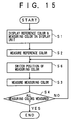
- FIG. 15 is a flow chart for explaining the operation of the CPU 201 in the third embodiment.
- steps which are the same as those corresponding steps in FIG. 8 are designated by the same reference numerals, and a description thereof will be omitted.
- This embodiment differs from the first embodiment described above, in that a step S6 is provided between the steps S2 and S3.
- the step S6 switches a display position of the measuring color on the display screen 102a, so that the measuring color at the switched display position is measured. If the decision result in the step S4 is NO, the process returns to the step S6.
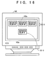
- FIGS. 16 and 17 are diagrams for explaining the switching of the display position.
- the reference color R is displayed in a region 121-3 and measuring colors M1 through M3 are displayed in a region 122-3 as shown in FIG. 16.
- the display position of the reference color R is switched into the region 122-3 as indicated by an arrow in FIG. 17, and the display position of the measuring color M1 which is to be measured first is switched into the region 121-3. Accordingly, when measuring the measuring color M1 in the step S3, the measuring color M1 is displayed within the region 121-3 as shown in FIG. 17.
- the area of the reference color R and the area of each of the measuring colors M1 through M3 which are respectively displayed within the region 121-3, are identical.
- the display areas of each of the colors identical to each other it becomes possible to accurately obtain the display characteristic of the display unit 102, even when the conditions such as the power control do not match.
- the display area of the measuring color were changed when the display region is moved, the total luminance of the screen would change by the power control and the measuring conditions would change. But it is possible to prevent the power control from being carried out, by making the display area of each of the measuring colors the same before and after the display region is moved.
- the power control is not carried out for each color displayed on the screen, but is carried out by taking into consideration the power consumption of the entire picture at that point in time.
- the display characteristic of the display unit is possible to know the display characteristic of the display unit from the CIE XYZ values of the colors R, G and B shown in FIG. 2 when the colors R, G, and B respectively have the maximum values Rmax, Gmax and Bmax, and from the input/output characteristics of the colors R, G and B shown in FIG. 3, that is, the ⁇ -characteristics. Accordingly, in order to create the profile of the display unit, it is necessary to know the wtpt value, the CIE XYZ values of the colors R, G and B when the colors R, G, and B respectively have the maximum values Rmax, Gmax and Bmax, and the ⁇ -characteristics of the colors R, G, and B.
- n a number of measurements made, to 1 or greater, and change the value n for each of the colors R, G and B.
- n a number of measurements made
- each of the colors displayed on the display unit cannot be measured under the same conditions. Consequently, the CIE XYZ values, for example, cannot be stored as they are in the profile, since the CIE XYZ values are values which are directly obtained by measuring the colors. Hence, a description will hereinafter be given of an embodiment which can create an accurate profile, even with respect to the display unit which carries out the power control or the like.
- This embodiment of the information processing apparatus simultaneously displays a reference color and at least one measuring color which is to be measured on the display unit, based on a program which is stored in a fourth embodiment of the storage medium according to the present invention, and creates a profile of the display unit by an embodiment of a profile data creating method according to the present invention by measuring the reference color and the measuring color which are displayed.
- the construction of this embodiment of the information processing apparatus may be the same as that of the first embodiment described above, and an illustration and description thereof will be omitted.
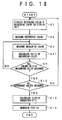
- FIG. 18 is a flow chart for explaining the operation of the CPU 201 in the fourth embodiment.
- steps which are the same as those corresponding steps in FIG. 8 are designated by the same reference numerals, and a description thereof will be omitted.
- This embodiment differs from the first embodiment described above, in that a step S11 is provided between the steps S3 and S4, and that steps S12 through S14 are provided after the step S4.
- the steps S2 and S3 measure the reference color and the measuring color which are displayed as shown in FIGS. 9 and 10, and store the measured values in the memory part 202.
- the step S11 calculates a ratio of the measured value of each measuring color with respect to the measured value of the reference color, and stores the calculated ratio in the memory part 202. For example, the measurements are made at the (3n+4) points described above, and the ratio of the measured value of each measuring color with respect to the measured value of the reference color is calculated. If the decision result in the step S4 is YES, the step S12 decides whether or not all of the reference colors are measured. The process returns to the step S2 if the decision result in the step S12 is NO.
- the step S13 calculates and stores in the memory part 202 the display characteristic of the display unit 102, that is, the data to be stored in the profile of the display unit 102, based on the ratios calculated in the step S11.
- the step S14 creates the profile of the display unit 102 based on the data calculated in the step S13, and stores the created profile in the memory part 202. The process ends after the step S14.
- This embodiment of the information processing apparatus simultaneously displays a reference color and at least one measuring color which is to be measured on the display unit, based on a program which is stored in a fifth embodiment of the storage medium according to the present invention, and creates a profile of the display unit by measuring the reference color and the measuring color which are displayed.
- the construction of this embodiment of the information processing apparatus may be the same as that of the first embodiment described above, and an illustration and description thereof will be omitted.
- FIG. 19 is a flow chart for explaining the operation of the CPU 201 in the fifth embodiment.
- steps which are the same as those corresponding steps in FIGS. 8 and 18 are designated by the same reference numerals, and a description thereof will be omitted.
- This embodiment differs from the first embodiment described above, in that the step S11 is provided between the steps S3 and S4, and that the steps S13 and S14 are provided after the step S4.
- the steps S2 and S3 measure all of the reference color and the measuring colors which are necessary to create the profile of the display unit 102 and are displayed as shown in FIG. 11, and store the measured values in the memory part 202.
- the step S11 calculates a ratio of the measured value of each measuring color with respect to the measured value of the reference color, and stores the calculated ratio in the memory part 202.
- all of the colors necessary to create the profile are displayed on the same display screen 102a, and thus, it is unnecessary to use a plurality of reference colors.
- the decision result in the step S4 is YES, the processes of the steps S13 and S14 are carried out, and the process ends.
- This embodiment of the information processing apparatus simultaneously displays a reference color and at least one measuring color which is to be measured on the display unit, based on a program which is stored in a sixth embodiment of the storage medium according to the present invention, and creates a profile of the display unit by measuring the reference color and the measuring color which are displayed.
- the construction of this embodiment of the information processing apparatus may be the same as that of the first embodiment described above, and an illustration and description thereof will be omitted.
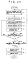
- FIG. 20 is a flow chart for explaining the operation of the CPU 201 in the sixth embodiment.
- steps which are the same as those corresponding steps in FIGS. 15 and 18 are designated by the same reference numerals, and a description thereof will be omitted.
- This embodiment differs from the third embodiment described above, in that the step S11 is provided between the steps S3 and S4, and that the steps S12 through S14 are provided after the step S4.
- the steps S2 and S3 measure the reference color and the measuring color which are switched and displayed as shown in FIGS. 16 and 17, and store the measured values in the memory part 202.
- the step S11 calculates a ratio of the measured value of each measuring color with respect to the measured value of the reference color, and stores the calculated ratio in the memory part 202.
- Other processes are the same as those of the fourth embodiment described above.
- the effects of the in-plane inconsistency may be reflected to the created profile of the display unit 102 and deteriorate the accuracy of the profile.
- the reference color and each measuring color are displayed and measured at the same position on the display screen 102a, so that it is possible to create a highly accurate profile which is unaffected by the in-plane inconsistency.
- the created profile is stored in the memory part 202.
- the storage location of the created profile is not limited to the memory part 202, and the created profile may be stored in the disk 110 within the disk drive 203, a hard disk within the hard disc drive 204, or in other storage means.
- the arrangement and the display area of the reference color and the measuring colors displayed on the display screen 102a of the display unit 102 are of course not limited to those of the embodiments described above.
- FIG. 21 is a functional block diagram showing the construction within the main body part 101 of the computer system 100 in this embodiment.
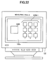
- a reference color patch storing part 1 stores a reference color patch 102R shown in FIG. 22 or FIG. 23 which is made up solely of one color.
- a measuring color patch storing part 2 stores a measuring color patch 102M-1 shown in FIG. 22 which is made up of a plurality of colors or, stores a measuring color patch 102M-2 shown in FIG. 23 which is made up of a plurality of colors.
- the measuring color patch 102M-1 is made up of 9 colors C1 through C9.
- the measuring color patch 102M-2 shown in FIG. 23 is made up of 6 colors C10 through C15.
- a color patch display part 3 simultaneously displays the reference color patch 102R and the measuring color patch 102M-1 or 102M-2 on the display screen 102a of the display unit 102.
- a measuring part 4 controls the color measuring device 115, and measures the colors displayed on the display screen 102a.
- the color of the reference color patch 102R, and the colors C1, C2, ..., C9 within the measuring color patch 102M-1 are successively measured in this order.
- the color of the reference color patch 102R, and the colors C10, C11, ..., C15 within the measuring color patch 102M-2 are successively measured in this order.
- a measured result of the reference color patch 102R is stored in a reference value storing part 5, and measured results of the measuring color patch 102M-1 or 102M-2 are temporarily stored in a measured color value storing part 6.
- the measured value of the reference color patch 102R stored in the reference value storing part 5 is supplied to a measured color ratio calculating part 7.
- the measured color ratio calculating part 7 calculates a ratio (measured ratio) of the measuring color patch 102M-1 or 102M-2 with respect to the reference color patch 102R, and stores the calculated ratio in the measured value storing part 6. If a color which is to be measured still remains after measuring the measuring color patch 102M-1 or 102M-2, a new measuring color patch and the reference color patch 102R identical to that used previously are displayed on the display screen 102a of the display unit 102.
- a reference value update part 8 instructs display of a new color patch, and instructs the reference value storing part 5 to discard the measured value of the previous reference color patch 102R and to store a new measured result by sending a reference value update signal. Every time a new measuring color patch is displayed, the reference value storing part 5 stores a re-measured result of the reference color patch in response to the reference value update signal.
- the profile creating part 9 creates the profile of the display unit 102 based on the received data.
- the reference color patch storing part 1, the measuring color patch storing part 2, the reference value storing part 5, and the measured value storing part 6 can be formed by the memory part 202, the disk drive 203 and/or the hard disk drive 204 shown in FIG. 7.
- the color chi display part 3, the measuring part 4, the measured color ratio calculating part 7, the reference value update part 8, and the profile creating part 9 can be formed by the CPU 201 shown in FIG. 7.
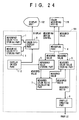
- FIG. 24 is a functional block diagram showing the construction within the main body part 101 of the computer system 100 in this embodiment.
- those parts which are the same as those corresponding parts in FIG. 21 are designated by the same reference numerals, and a description thereof will be omitted.
- a display switch part 12 is provided in place of the reference value update part 8 shown in FIG. 21.
- This display switch part 12 can be formed by the CPU 201 shown in FIG. 7.
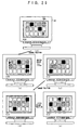
- the display switch part 12 makes a display according to a flow shown in FIG. 25 (a) through (f).
- a reference color patch 102R-1 and a color C21 are displayed on the display screen 102a, and the reference color patch 102R-1 is measured.
- FIG. 25 (b) display positions of the reference color patch 102R-1 and the color C21 are switched, and the color C21 is measured at the same measuring position as in FIG. 25 (a). Then, as shown in FIG.
- the reference color patch 102R-1 and a color C22 are displayed on the display screen 102a, and the reference color patch 102R-1 is measured. Further, as shown in FIG. 25 (d), the display positions of the reference color patch 102R-1 and the color C22 are switched, and the color C22 is measured at the same measuring position as in FIG. 25 (c). Next, as shown in FIG. 25 (e), the reference color patch 102R-1 and a color C23 are displayed on the display screen 102a, and the reference color patch 102R-1 is measured. Then, as shown in FIG. 25 (f), the display positions of the reference color patch 102R-1 and the color C23 are switched, and the color C23 is measured at the same measuring position as in FIG. 25 (e).
- the measuring position is fixed, and the display positions of the color patchs are successively switched.
- An in-plane inconsistency may be generated and the display characteristic of the display unit 102 may differ depending on the position on the display screen 102a.
- this embodiment can create a highly accurate profile of the display unit 102.
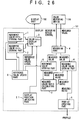
- FIG. 26 is a functional block diagram showing the construction within the main body part 101 of the computer system 100 in this embodiment.
- those parts which are the same as those corresponding parts in FIG. 21 are designated by the same reference numerals, and a description thereof will be omitted.
- This embodiment is provided with a display position switching part 21.
- This display position switching part 21 can be formed by the CPU 201 shown in FIG. 7.
- the display position switching part 21 successively switches the display positions and displays a reference color patch 102R-2 and a plurality of measuring color patchs C31 and C32 which are respectively made up of a plurality of colors, according to a flow shown in FIG. 27 (a) through (f).
- a display position switching part 21 can be formed by the CPU 201 shown in FIG. 7.
- the display position switching part 21 successively switches the display positions and displays a reference color patch 102R-2 and a plurality of measuring color patchs C31 and C32 which are respectively made up of a plurality of colors, according to a flow shown in FIG. 27 (a) through (f).
- FIG. 28 is a functional block diagram showing the construction within the main body part 101 of the computer system 100 in this embodiment.
- those parts which are the same as those corresponding parts in FIG. 21 are designated by the same reference numerals, and a description thereof will be omitted.
- the color patch stored in the measuring color patch storing part 2 includes all of the colors which must be measured in order to create the profile. In addition, all of these colors which must be measured in order to create the profile are simultaneously displayed on the display screen 102a, so that the reference value update part 8 and the display position switch part 21 can be omitted.
- the present invention is applied to a display unit which carries out the power control.
- the present invention is of course also applicable to display units such as a CRT which does not carry out the power control. Accordingly, the program for creating the profile according to the present invention can be used in common with respect to the display unit which carries out the power control and the display unit which does not carry out the power control, and is practical.
Landscapes
- Physics & Mathematics (AREA)
- Spectroscopy & Molecular Physics (AREA)
- General Physics & Mathematics (AREA)
- Engineering & Computer Science (AREA)
- Mathematical Physics (AREA)
- Theoretical Computer Science (AREA)
- Controls And Circuits For Display Device (AREA)
- User Interface Of Digital Computer (AREA)
- Digital Computer Display Output (AREA)
- Spectrometry And Color Measurement (AREA)
Applications Claiming Priority (2)
| Application Number | Priority Date | Filing Date | Title |
|---|---|---|---|
| JP26513698A JP4136114B2 (ja) | 1998-09-18 | 1998-09-18 | 情報処理装置、プロファイルデータ作成方法、表示装置及び記憶媒体 |
| JP26513698 | 1998-09-18 |
Publications (3)
| Publication Number | Publication Date |
|---|---|
| EP0987528A2 true EP0987528A2 (fr) | 2000-03-22 |
| EP0987528A3 EP0987528A3 (fr) | 2000-12-06 |
| EP0987528B1 EP0987528B1 (fr) | 2005-11-09 |
Family
ID=17413132
Family Applications (1)
| Application Number | Title | Priority Date | Filing Date |
|---|---|---|---|
| EP99304346A Expired - Lifetime EP0987528B1 (fr) | 1998-09-18 | 1999-06-03 | Dispositif de traitement de l'information avec unité d'affichage couleur |
Country Status (4)
| Country | Link |
|---|---|
| US (1) | US6734869B2 (fr) |
| EP (1) | EP0987528B1 (fr) |
| JP (1) | JP4136114B2 (fr) |
| DE (1) | DE69928194T2 (fr) |
Cited By (2)
| Publication number | Priority date | Publication date | Assignee | Title |
|---|---|---|---|---|
| WO2006002978A1 (fr) * | 2004-07-06 | 2006-01-12 | Axana-Müller, Susi | Procede et systeme pour la determination automatique de couleurs et programme d'ordinateur et support d'information associe lisible par ordinateur |
| EP2752647A1 (fr) * | 2013-01-07 | 2014-07-09 | Seiko Epson Corporation | Dispositif de mesure spectroscopique, système de gestion de couleurs et procédé de génération de profil |
Families Citing this family (13)
| Publication number | Priority date | Publication date | Assignee | Title |
|---|---|---|---|---|
| JP3960694B2 (ja) * | 1998-10-26 | 2007-08-15 | 富士通株式会社 | 色信号変換方法、色信号変換装置、記録媒体、デバイスドライバ及び色変換テーブル |
| WO2001015129A1 (fr) * | 1999-08-25 | 2001-03-01 | Fujitsu Limited | Procede de mesure d'affichage et procede de preparation de profil |
| US7038811B1 (en) * | 2000-03-31 | 2006-05-02 | Canon Kabushiki Kaisha | Standardized device characterization |
| JP4303956B2 (ja) | 2000-07-12 | 2009-07-29 | 大日精化工業株式会社 | 色彩を忠実に伝達する画像処理装置および画像データの提供方法 |
| JP3760815B2 (ja) * | 2001-07-27 | 2006-03-29 | 株式会社日立製作所 | 映像表示装置 |
| US7265778B2 (en) * | 2001-08-09 | 2007-09-04 | Eastman Kodak Company | Visual display characterization |
| JP3754943B2 (ja) * | 2002-08-19 | 2006-03-15 | キヤノン株式会社 | 画像処理方法、装置、記憶媒体及びプログラム |
| TWI220632B (en) * | 2003-05-23 | 2004-08-21 | Printing Technology Res Inst | Method for generating color monitor profile for different operating systems |
| US20060181721A1 (en) * | 2005-02-11 | 2006-08-17 | Kulkarni Manish S | Motion picture content preview |
| US9024963B2 (en) * | 2007-11-14 | 2015-05-05 | Adobe Systems Incorporated | Selecting color spaces for cinema or video data |
| DE102008053677B4 (de) * | 2008-10-29 | 2010-09-16 | Ab Skf | Verfahren zum Prüfen der Oberfläche eines Werkstücks |
| JP6136357B2 (ja) * | 2013-02-25 | 2017-05-31 | セイコーエプソン株式会社 | 分光測定装置、通信システム及びカラーマネージメントシステム |
| US9256815B1 (en) * | 2014-07-30 | 2016-02-09 | Hewlett-Packard Development Company, L.P. | Spectral print control based on specific spectral ranges of colorants |
Family Cites Families (15)
| Publication number | Priority date | Publication date | Assignee | Title |
|---|---|---|---|---|
| US3748046A (en) * | 1971-12-13 | 1973-07-24 | Harris Intertype Corp | Measurement of reflection density |
| US3961242A (en) * | 1975-04-30 | 1976-06-01 | Dynascan Corporation | Emission testing circuit for color cathode ray tubes |
| GB8814157D0 (en) | 1988-06-15 | 1988-07-20 | Crosfield Electronics Ltd | Display control system |
| JP2699688B2 (ja) | 1991-04-19 | 1998-01-19 | 松下電器産業株式会社 | 誤差自己補正式色彩計 |
| EP0604755B1 (fr) | 1992-12-15 | 1999-05-12 | E.I. Du Pont De Nemours And Company | Méthode et appareil pour l'égalisation de couleur |
| EP0650291B1 (fr) * | 1993-09-29 | 2002-04-24 | Canon Kabushiki Kaisha | Appareil et procédé de traitement d'images |
| US6075888A (en) | 1996-01-11 | 2000-06-13 | Eastman Kodak Company | System for creating a device specific color profile |
| JP3485708B2 (ja) * | 1996-01-29 | 2004-01-13 | 理想科学工業株式会社 | 分版用データ処理装置及び方法と製版処理装置及び方法 |
| JP3427615B2 (ja) | 1996-04-30 | 2003-07-22 | トヨタ自動車株式会社 | 色再現方法 |
| JPH09312859A (ja) * | 1996-05-23 | 1997-12-02 | Sony Corp | カラー表示装置の画質測定装置及び画質測定方法 |
| JPH10285416A (ja) * | 1997-04-04 | 1998-10-23 | Dainippon Screen Mfg Co Ltd | カラー画像データ出力装置 |
| US6108442A (en) * | 1997-06-27 | 2000-08-22 | Minnesota Mining And Manufacturing Company | Characterization of color imaging systems |
| US6269482B1 (en) * | 1997-07-14 | 2001-07-31 | Altinex, Inc. | Methods of testing electrical signals and compensating for degradation |
| US6229626B1 (en) * | 1997-10-24 | 2001-05-08 | Eastman Kodak Company | Method apparatus and product providing direct calculation of the color gamut of color reproduction processes |
| US6313823B1 (en) * | 1998-01-20 | 2001-11-06 | Apple Computer, Inc. | System and method for measuring the color output of a computer monitor |
-
1998
- 1998-09-18 JP JP26513698A patent/JP4136114B2/ja not_active Expired - Fee Related
-
1999
- 1999-05-21 US US09/315,991 patent/US6734869B2/en not_active Expired - Fee Related
- 1999-06-03 EP EP99304346A patent/EP0987528B1/fr not_active Expired - Lifetime
- 1999-06-03 DE DE69928194T patent/DE69928194T2/de not_active Expired - Lifetime
Cited By (2)
| Publication number | Priority date | Publication date | Assignee | Title |
|---|---|---|---|---|
| WO2006002978A1 (fr) * | 2004-07-06 | 2006-01-12 | Axana-Müller, Susi | Procede et systeme pour la determination automatique de couleurs et programme d'ordinateur et support d'information associe lisible par ordinateur |
| EP2752647A1 (fr) * | 2013-01-07 | 2014-07-09 | Seiko Epson Corporation | Dispositif de mesure spectroscopique, système de gestion de couleurs et procédé de génération de profil |
Also Published As
| Publication number | Publication date |
|---|---|
| JP4136114B2 (ja) | 2008-08-20 |
| US6734869B2 (en) | 2004-05-11 |
| DE69928194T2 (de) | 2006-05-24 |
| DE69928194D1 (de) | 2005-12-15 |
| US20020093509A1 (en) | 2002-07-18 |
| EP0987528A3 (fr) | 2000-12-06 |
| JP2000099305A (ja) | 2000-04-07 |
| EP0987528B1 (fr) | 2005-11-09 |
Similar Documents
| Publication | Publication Date | Title |
|---|---|---|
| EP0987528B1 (fr) | Dispositif de traitement de l'information avec unité d'affichage couleur | |
| JP4427125B2 (ja) | 表示特性認識装置、表示特性認識プログラム記憶媒体、表示特性調整装置および表示特性調整プログラム記憶媒体 | |
| US6453066B1 (en) | Image processing method and image processing apparatus | |
| EP1294177B1 (fr) | Procédé et appareil de traitement d'images | |
| US6954213B1 (en) | Objective automated color matching between input and output devices | |
| US7158144B2 (en) | Image processing apparatus and method for converting data dependent on a first illuminating light into data dependent on a second illuminating light | |
| US5909291A (en) | Color matching apparatus and method | |
| US6549654B1 (en) | Image processing method and apparatus and storage medium storing processes of executing the method | |
| KR20040012873A (ko) | 집적된 컬러 매칭 프로세서를 구비한 컬러 디스플레이 장치 | |
| US7190372B2 (en) | Display characterization method and apparatus | |
| JP2005210370A (ja) | 画像処理装置、撮影装置、画像処理方法及び画像処理プログラム | |
| US6078309A (en) | System and method for visually measuring color characteristics of a display | |
| JP2007163979A (ja) | プロファイル作成装置、プロファイル作成プログラム、および画像出力装置 | |
| US20060209320A1 (en) | Image forming apparatus and method for the same | |
| JPH1132228A (ja) | 送信装置、送信方法、受信装置、受信方法、画像処理システム、画像処理方法、画像データ処理装置、画像データ処理方法、並びに提供媒体 | |
| US20080174798A1 (en) | Color-management apparatus and method | |
| US6240204B1 (en) | Image data conversion on the basis of observation light of an output image | |
| US6313823B1 (en) | System and method for measuring the color output of a computer monitor | |
| JPH0787345A (ja) | カラーマッチング方法及びその装置 | |
| JPH1141478A (ja) | 画像処理方法、装置および記録媒体 | |
| JPH11155076A (ja) | 色変換方法、色変換テーブル作成装置、色変換装置、および記録媒体 | |
| JP2004064546A (ja) | 画像処理装置及び色再現方法 | |
| JP3271487B2 (ja) | アプルーバル特性付画像データベースおよび画像処理装置 | |
| JP2007081581A (ja) | 色処理方法及びその装置 | |
| JP2002344760A (ja) | モニタ画像の白色点測定方法 |
Legal Events
| Date | Code | Title | Description |
|---|---|---|---|
| PUAI | Public reference made under article 153(3) epc to a published international application that has entered the european phase |
Free format text: ORIGINAL CODE: 0009012 |
|
| AK | Designated contracting states |
Kind code of ref document: A2 Designated state(s): DE FR GB |
|
| AX | Request for extension of the european patent |
Free format text: AL;LT;LV;MK;RO;SI |
|
| PUAL | Search report despatched |
Free format text: ORIGINAL CODE: 0009013 |
|
| AK | Designated contracting states |
Kind code of ref document: A3 Designated state(s): AT BE CH CY DE DK ES FI FR GB GR IE IT LI LU MC NL PT SE |
|
| AX | Request for extension of the european patent |
Free format text: AL;LT;LV;MK;RO;SI |
|
| 17P | Request for examination filed |
Effective date: 20010131 |
|
| AKX | Designation fees paid |
Free format text: DE FR GB |
|
| 17Q | First examination report despatched |
Effective date: 20040126 |
|
| GRAP | Despatch of communication of intention to grant a patent |
Free format text: ORIGINAL CODE: EPIDOSNIGR1 |
|
| GRAS | Grant fee paid |
Free format text: ORIGINAL CODE: EPIDOSNIGR3 |
|
| GRAA | (expected) grant |
Free format text: ORIGINAL CODE: 0009210 |
|
| AK | Designated contracting states |
Kind code of ref document: B1 Designated state(s): DE FR GB |
|
| REG | Reference to a national code |
Ref country code: GB Ref legal event code: FG4D |
|
| REF | Corresponds to: |
Ref document number: 69928194 Country of ref document: DE Date of ref document: 20051215 Kind code of ref document: P |
|
| ET | Fr: translation filed | ||
| PLBE | No opposition filed within time limit |
Free format text: ORIGINAL CODE: 0009261 |
|
| STAA | Information on the status of an ep patent application or granted ep patent |
Free format text: STATUS: NO OPPOSITION FILED WITHIN TIME LIMIT |
|
| 26N | No opposition filed |
Effective date: 20060810 |
|
| PGFP | Annual fee paid to national office [announced via postgrant information from national office to epo] |
Ref country code: GB Payment date: 20130529 Year of fee payment: 15 Ref country code: DE Payment date: 20130529 Year of fee payment: 15 |
|
| PGFP | Annual fee paid to national office [announced via postgrant information from national office to epo] |
Ref country code: FR Payment date: 20130624 Year of fee payment: 15 |
|
| REG | Reference to a national code |
Ref country code: DE Ref legal event code: R119 Ref document number: 69928194 Country of ref document: DE |
|
| GBPC | Gb: european patent ceased through non-payment of renewal fee |
Effective date: 20140603 |
|
| REG | Reference to a national code |
Ref country code: DE Ref legal event code: R119 Ref document number: 69928194 Country of ref document: DE Effective date: 20150101 |
|
| REG | Reference to a national code |
Ref country code: FR Ref legal event code: ST Effective date: 20150227 |
|
| PG25 | Lapsed in a contracting state [announced via postgrant information from national office to epo] |
Ref country code: DE Free format text: LAPSE BECAUSE OF NON-PAYMENT OF DUE FEES Effective date: 20150101 |
|
| PG25 | Lapsed in a contracting state [announced via postgrant information from national office to epo] |
Ref country code: FR Free format text: LAPSE BECAUSE OF NON-PAYMENT OF DUE FEES Effective date: 20140630 Ref country code: GB Free format text: LAPSE BECAUSE OF NON-PAYMENT OF DUE FEES Effective date: 20140603 |