EP0987532A2 - Dispositif de mesure pour la détermination du couple de serrage total, du moment de friction d'une tête de vis et de la force de précontrainte d'une connexion à vis serrée - Google Patents
Dispositif de mesure pour la détermination du couple de serrage total, du moment de friction d'une tête de vis et de la force de précontrainte d'une connexion à vis serrée Download PDFInfo
- Publication number
- EP0987532A2 EP0987532A2 EP99116864A EP99116864A EP0987532A2 EP 0987532 A2 EP0987532 A2 EP 0987532A2 EP 99116864 A EP99116864 A EP 99116864A EP 99116864 A EP99116864 A EP 99116864A EP 0987532 A2 EP0987532 A2 EP 0987532A2
- Authority
- EP
- European Patent Office
- Prior art keywords
- dependent
- measuring point
- clamping sleeve
- measuring
- head friction
- Prior art date
- Legal status (The legal status is an assumption and is not a legal conclusion. Google has not performed a legal analysis and makes no representation as to the accuracy of the status listed.)
- Granted
Links
- 230000001419 dependent effect Effects 0.000 claims abstract description 184
- 238000005452 bending Methods 0.000 claims abstract description 29
- 230000036316 preload Effects 0.000 claims description 32
- 239000012528 membrane Substances 0.000 claims description 28
- 239000000463 material Substances 0.000 claims description 10
- 210000002105 tongue Anatomy 0.000 claims description 9
- 238000003466 welding Methods 0.000 claims description 5
- 239000011324 bead Substances 0.000 claims description 4
- 230000035945 sensitivity Effects 0.000 claims description 4
- 238000000034 method Methods 0.000 claims description 2
- 210000004379 membrane Anatomy 0.000 description 24
- 230000006835 compression Effects 0.000 description 11
- 238000007906 compression Methods 0.000 description 11
- 238000005259 measurement Methods 0.000 description 9
- 241000209035 Ilex Species 0.000 description 6
- 239000002655 kraft paper Substances 0.000 description 6
- 229910000831 Steel Inorganic materials 0.000 description 4
- 238000013461 design Methods 0.000 description 4
- 239000010959 steel Substances 0.000 description 4
- 230000005540 biological transmission Effects 0.000 description 3
- 238000004026 adhesive bonding Methods 0.000 description 2
- 238000009760 electrical discharge machining Methods 0.000 description 2
- 238000007689 inspection Methods 0.000 description 2
- 238000003801 milling Methods 0.000 description 2
- 238000000275 quality assurance Methods 0.000 description 2
- 230000009467 reduction Effects 0.000 description 2
- 238000012827 research and development Methods 0.000 description 2
- 230000004323 axial length Effects 0.000 description 1
- 230000009286 beneficial effect Effects 0.000 description 1
- 230000002146 bilateral effect Effects 0.000 description 1
- 238000006243 chemical reaction Methods 0.000 description 1
- 238000010276 construction Methods 0.000 description 1
- 238000011161 development Methods 0.000 description 1
- 230000018109 developmental process Effects 0.000 description 1
- 238000006073 displacement reaction Methods 0.000 description 1
- 230000000694 effects Effects 0.000 description 1
- 239000013013 elastic material Substances 0.000 description 1
- 239000004744 fabric Substances 0.000 description 1
- 238000000227 grinding Methods 0.000 description 1
- 238000011089 mechanical engineering Methods 0.000 description 1
- 230000000452 restraining effect Effects 0.000 description 1
- 238000010008 shearing Methods 0.000 description 1
Images


Classifications
-
- G—PHYSICS
- G01—MEASURING; TESTING
- G01L—MEASURING FORCE, STRESS, TORQUE, WORK, MECHANICAL POWER, MECHANICAL EFFICIENCY, OR FLUID PRESSURE
- G01L5/00—Apparatus for, or methods of, measuring force, work, mechanical power, or torque, specially adapted for specific purposes
- G01L5/24—Apparatus for, or methods of, measuring force, work, mechanical power, or torque, specially adapted for specific purposes for determining value of torque or twisting moment for tightening a nut or other member which is similarly stressed
Definitions
- the invention relates to a measuring device for determining the total tightening torque M A , the head friction torque M K and the pretensioning force F V of a tightened screw connection held in a force / moment transducer by measuring the resulting stresses according to the preamble of claim 1.
- a thread friction torque M G increasing with the tensile force F V and a head friction torque M K must be overcome.
- the thread friction torque M G results from the form-fitting sliding surfaces, the so-called screw surfaces (usually control surfaces) of the two parts.
- the head friction moment M K results from the friction of the sliding surfaces under the nut or under the screw head, depending on which part is turned when the screw connection is tightened.
- the total tightening torque M A applied when tightening the screw connection is additively composed of the friction moments M G and M K and is therefore dependent on the preload force F V and the coefficients of friction, the latter of course being material-dependent.
- a calculation of the thread friction torque M G which is often not directly measurable, presents difficulties insofar as the measurable parameters, namely M A , M K and F V , but especially the head friction torque M K , cannot be determined with sufficient accuracy using known measuring devices. This makes it difficult to make a reliable statement about the quality and reliability of a screw connection, which is a hindrance, particularly in the automotive industry, which works according to international standards and house standards.
- a measuring device for determining the total tightening torque M A , the head friction torque M K and the pretensioning force F V is known for example from DE 25 21 428 C2.
- the measuring device consists of an essentially cylindrical housing with a lower base plate oriented parallel to the cylinder axis of the housing. At a first end, the housing has an inner flange provided with an inner shoulder. The outer ring of a ball bearing is attached to the inner shoulder. At the opposite second end of the housing, a steel ring representing an inner flange is screwed on, which receives the outer ring of a further ball bearing in an upper recess, which projects with an integrally formed, annular section into the housing.
- a clamping sleeve is rotatably mounted near its two end faces via the ball bearings and with low friction in the housing, but is bound to the steel ring fixed to the housing via two arms which protrude diametrically from the circumference of the clamping sleeve.
- the arms have a reduced cross-section at their end adjacent to the clamping sleeve.
- the free ends of the arms are each articulated to the ring via a cylindrical pin.
- the screw connection to be tested is clamped via insert pieces in the clamping sleeve, which is designed as a relatively thin-walled torsion cell in its central region.
- the torsional stress dependent on the head friction moment M K and the compressive stress dependent on the axial preload force F V are measured in the clamping sleeve, the amount of which corresponds to the tensile stress of interest in the screw connection, using at least two sets of strain gauges attached to the outside.
- the entire tightening torque M A applied when tightening the screw connection occurs as a bending stress in the region of the flexible arms and is detected by strain gauges additionally arranged in the cross-sectional reductions of the arms.
- the thread friction torque M G can be calculated from the difference between the total tightening torque M A and the head friction torque M K.
- a deformation of the clamping sleeve occurs during tightening of the screw connection.
- the overall deformation of the clamping sleeve consists of a pure compression (compressive stress) and a pure shear (torsional stress), which can be described by the following angular conditions:
- the compression (compressive stress) can be determined by two strain gauges at 90 ° to each other, one parallel and the other transverse to the longitudinal axis of the clamping sleeve is completely grasped.
- the shear (torsional stress) can be completely measured by two strain gauges at 90 ° to each other and 45 ° inclined to the longitudinal axis of the clamping sleeve.
- the clamping sleeve is compressed along its longitudinal axis by the prestressing force F V and sheared perpendicular to it by M K / R, where R is the radius of the clamping sleeve which is assumed to be large compared to its wall thickness D.
- the torsional stress which is dependent on the head friction torque M K , does not result in any further compression (compressive stress) along the longitudinal axis of the clamping sleeve. Similarly, the axial compression (compressive stress) does not lead to further shear (torsional stress).
- the sets of strain gauges applied to the torsion and compression elastic clamping sleeve, which ultimately act as a spring are exposed both to the torsional stress dependent on the head friction torque M K and to the compressive stress dependent on the axial pretensioning force F V. Since the angular conditions described above, especially when attaching the strain gauges, cannot always be reliably met, the strain gauges also detect a small portion of the compressive stress dependent on the axial preload force F V , for example, for the torsional stress dependent on the head friction torque M K, and vice versa.
- Decisive for the compression (compressive stress) of the clamping sleeve and the elongation (tensile stress) of the bolt under the preload force F V are their load-bearing cross-sections and the elastic moduli of their materials.
- the modulus of elasticity of the bolt is generally the same as that of the clamping sleeve; both are preferably made of steel.
- the supporting cross-section of the clamping sleeve is chosen to be as small as possible in the interest of an easily measurable, large compression (compressive stress).
- the load-bearing cross-section of the bolt is also mine in the interest of saving material.
- the lower limit of the load-bearing cross-sections is determined by the requirement that no permanent deformation may occur during operation. This requirement applies equally to the clamping sleeve and screw connection. Therefore, the cross sections carrying the prestressing force F V are essentially the same size for the screw bolt and the clamping sleeve.
- the elastic material properties namely the shear modulus
- the bolt is designed so that approximately the maximum permissible torsional deformation occurs.
- the decisive factor for the torsional deformation is, however, in addition to the shear modulus and the amount of the load-bearing cross-section, its radius with respect to the axis of rotation, i.e. the screw axis or longitudinal axis of the clamping sleeve, and this is inevitably considerably larger for the clamping sleeve than for the screw bolt, since the former encloses the latter coaxially. Therefore, the torsion deformation in the clamping sleeve is considerably smaller than in the screw bolt.
- An electrical output signal (useful variable) of the associated strain gauge is consequently significantly smaller than that for compression (compressive stress), or in other words, significantly more sensitive to crosstalk (disturbance variable) of other measured variables.
- the ratio of the measurement signals (useful variables) for the torsional stress dependent on the head friction torque M K is only about 1/5 to 1/3 of that for the compressive stress dependent on the prestressing force F V.
- the provision of means for mechanical decoupling advantageously prevents crosstalk (disturbance variable) of a measured variable into the measuring point of the other measured variable and increases measuring accuracy, in particular for the head friction torque M K , so that on the one hand the thread friction torque M G is more accurate can be determined and thereby enables a better assured statement about the quality and reliability of a screw connection and, on the other hand, the screw connection can be designed in such a way that risks regarding loosening or loosening of the screw connection can be better excluded under operating load.
- the field of application of the invention extends not only to quality assurance, but also, for example, to incoming goods inspection and research and development, preferably in the automotive industry.
- a force / torque transducer which has a torsionally and pressure-elastic cylindrical central clamping sleeve, on which at least one measuring point for the torsional stress dependent on the head friction torque M K and at least one measuring point for the compressive stress dependent on the axial preload force F V are arranged is characterized in that the means for decoupling the measuring point for the torsional stress dependent on the head friction moment M K at least partially cancel out the compressive stresses in the clamping sleeve or channel the torsional stresses.
- At least one relief slot is provided adjacent to this in the central clamping sleeve and extends transversely, preferably approximately at right angles, to the longitudinal axis thereof, which advantageously advantageously at least partially Eliminates compressive stress in the clamping sleeve.
- the decoupling can preferably be strengthened in that, in addition to the relief slot, at least one, adjacent to the decoupled measuring point for the torsional stress dependent on the head friction moment M K is introduced in the central clamping sleeve and extends essentially parallel to the longitudinal axis of the substantially rectangular relief recess.
- a further increase in the decoupling effects is preferably achieved in that a second relief slot is provided adjacent to the measuring point for the torsional stress dependent on the head friction moment M K , which is arranged essentially parallel to the first relief slot, the length of the relief slots being greater than the length of a rectangle their distance from one another is preferably at least one and a half times, in particular twice as large, so that a web-shaped section is formed between the relief slots.
- the web-shaped section have a smaller wall thickness or material thickness d than the remaining wall thickness D of the central clamping sleeve.
- At least one relief slot and at least one relief recess be arranged approximately at right angles to one another so that there is a narrow tongue, preferably two narrow tongues, between them. are formed, which connect the web-shaped section with the remaining clamping sleeve, the narrow or thin tongues being advantageously freed from the influences of a compressive stress dependent on the prestressing force F V by the relief recesses.
- the sides of the relief recesses facing the measuring point for the torsional stress dependent on the head friction torque M K are preferably designed as a straight line.
- the sides of the relief recesses facing the measuring point for the torsional stress dependent on the head friction moment M K be designed so that the web-shaped Section at least in the area of the measuring point for the torsional stress dependent on the head friction torque M K has a local constriction, the lateral expansion of the relief recesses in the central region of the measuring point for the sides of the relief recesses facing the head frictional moment M K dependent preferably being formed and shaped like a segment of a circle or triangular or is reproduced another geometric shape.
- the measuring point for determining a compressive stress dependent on the prestressing force F V and the measuring point mechanically decoupled therefrom for determining a torsional stress dependent on the head friction torque M K are preferably alternately and evenly spaced on the central clamping sleeve, preferably two measuring points alternately and at an angle of 90 ° to each other.
- An alternative design of a force / moment transducer with a torsionally and pressure-elastic cylindrical central clamping sleeve, on which only the measuring points for the compressive stress dependent on the axial preload force F V are arranged is preferably characterized according to the invention in that the measuring points for the Head friction torque M K dependent torsional stress on an outer sleeve, which coaxially surrounds the central clamping sleeve, are arranged by means of additional mechanical decoupling of the measuring points for the torsional stress dependent on the head friction torque M K from the compressive stress dependent on the axial preload force F V with the central one Clamping sleeve is in particular connected without play, the means being advantageously elastic and torsionally rigid.
- the outer sleeve is a bilateral is an open cylinder, the two ends of which each have an inner flange, being between opposite flanges of a central clamping sleeve a circular membrane is arranged in each case and the outer sleeve.
- the outer sleeve has a preferably pot-like shape, with an inner flange formed adjacent to the outer edge of its open side and a circular base plate with a hole through which the central Clamping sleeve extends through, so that the bottom of the outer sleeve over the base plate on the second, preferably rectangular, flange of the central one Collet and on its open side over one between the ones opposite flanges of the central clamping sleeve and outer sleeve arranged circular membrane is pressure-elastic and torsionally rigid
- the circular membrane In order to minimize crosstalk of the compressive stress, which is dependent on the prestressing force F V , into a measuring point for the torsional stress, which is dependent on the head friction moment M K , it is proposed that the circular membrane have at least one circumferential bead.
- At least one pressure-elastic torsion-resistant bellows or compensator is provided, which is preferably between the first, preferably cylindrical, flange and the measuring point arranged on the outer sleeve is arranged for the torsional stress dependent on the head friction moment M K.
- a second pressure-elastic torsion-resistant bellows or compensator is provided, which is preferably between the measuring point for the torsional stress dependent on the head friction torque M K and a circular one connected to the second, preferably rectangular, flange Tarpaulin is arranged.
- the bellows or compensators have at least one rotating shaft.
- Outer sleeve, membrane, bellows or compensator and / or central clamping sleeve are preferably by known connection techniques, in particular by Screwing and / or welding, can be connected to each other rigidly or without play.
- a further mechanical decoupling of the measuring point for the torsional stress dependent on the head friction torque M K from the compressive stress dependent on the axial preload force F V is preferably carried out according to the invention by a suitable choice of a geometric arrangement of the measuring point for the torsional stress dependent on the head friction moment M K on the outer sleeve, in particular by Selection of a length L of the measuring point range for the torsional stress on the outer sleeve, which is dependent on the head friction torque M K , a radius R of the outer sleeve, and a thickness d of the outer sleeve (17) in the region of the measuring point for the torsional stress dependent on the head friction torque M K , whereby to increase a torsional deformation, the wall thickness d of the outer sleeve in the area of the measuring point for the torsional stress dependent on the head friction moment M K is preferably less than the remaining wall thickness D of the outer sleeve.
- the outer sleeve additionally have radial bores.
- the measuring points for determining a compressive stress on the central clamping sleeve, which is dependent on the prestressing force F V, and the measuring point mechanically decoupled therefrom for determining a torsional stress on the outer sleeve, which is dependent on the head friction moment M K are alternating, preferably alternating in pairs, i.e. preferably two pairs of measuring points alternately and arranged at an angle of 90 ° relative to each other.
- the outer sleeve has a recess for the compressive stress dependent on the prestressing force F V, in each case via the measuring points arranged on the central clamping sleeve, the dimensions of which in any case is dimensioned such that the strain gauges can be placed on the central clamping sleeve and nevertheless a transmission or introduction of the torsional stress dependent on the head friction moment M K into the measuring point provided on the outer sleeve is ensured.
- the outer sleeve is particularly simple in construction characterized in that the outer sleeve is preferably approximately in all areas has uniform material thickness D.
- the force / moment transducer according to the invention with a torsionally and pressure-elastic cylindrical central clamping sleeve which is rotatably supported in a housing, the support of the clamping sleeve in the housing at one end, preferably at the end, at which the second, preferably rectangular , Flange is formed, takes place via two diametrically protruding flexible arms projecting from the clamping sleeve, are characterized in that at least one, preferably one, ie at least one measuring point for the bending stress depending on the total tightening torque M A is provided on the flexible arms
- M A ie at least one measuring point for the bending stress depending on the total tightening torque M A
- Fig. 1 shows schematically a torsionally and pressure-elastic cylindrical central clamping sleeve 7 of a force / moment transducer 1 in a perspective view, on which at least one measuring point 5 for a torsional stress dependent on the head friction torque M K and at least one measuring point 6 for an axial pretensioning force F V dependent compressive stress are arranged.
- the central clamping sleeve 7 has two end faces.
- a first, preferably a circular or cylindrical flange 22 with a through opening 30 for inserting a screw bolt 2 is formed on one end end.
- a second, preferably a rectangular, flange 23 is formed with two flexurally elastic arms 28, 29 which protrude diametrically from the circumference and which are integrally formed on the second flange 23.
- Flange 23 like the first flange 22, has a through opening 30 in its center along its center, through which the free end 2a of the screw bolt 2 is guided and screwed tight with a nut 3 so that the screw head 2b of the screw bolt 2 on the first flange 22 is present.
- the first, preferably cylindrical, flange 22 is roller-mounted in an outer housing (not shown). Via the second, preferably rectangular, flange 23, the entire tightening torque M A applied when the screw connection (2, 3) is tightened is likewise diverted into the housing via the two flexible arms 28, 29.
- At least one measuring point 5 is provided on the central clamping sleeve 7, somewhat enlarged.
- two identical measuring points 5 are provided, which are offset by 180 ° on the circumference of the clamping sleeve 7, for measuring the torsional stress dependent on the head friction torque M K.
- the strain gauges 50 arranged for this purpose in a measuring point 5 are offset from one another at an angle of 90 °.
- the angle of the strain gauges 50 is 45 ° to the longitudinal axis 8 of the clamping sleeve 7.
- Another measuring point 6 is used to measure a compressive stress dependent on the axial prestressing force F V and is also arranged on the central clamping sleeve 7.
- two strain gauges 60 are arranged, one strain gauge being arranged parallel and the other transverse to the longitudinal axis 8 of the central clamping sleeve 7.
- At least one measuring point 4 is provided on the two preferably cuboidal elastic arms 28, 29, which comprises two strain gauges 40 which, like the strain gauges 60, are aligned with each other and with the longitudinal axis 8 of the central clamping sleeve 7 .
- strain gauges 40, 50, 50a, 60 there are always at least two pairs of strain gauges 40, 50, 50a, 60 arranged so that a Wheatstone bridge can be formed.
- the measuring point 5, 5a according to the invention for the torsional stress dependent on the head frictional moment M K is influenced by mechanical means from an influence of decoupled from the axial preload force F V dependent compressive stress.
- the mechanical decoupling is achieved, in particular, by means of relief slots 9, 10 or relief recesses 11, 12 which are introduced into the central clamping sleeve 7.
- the relief slots 9, 10 are introduced on the central clamping sleeve 7 transversely to the longitudinal axis 8 of the clamping sleeve 7.
- the length of the relief slots 9, 10 is preferably greater than their spacing from one another, preferably one and a half times as large, in particular twice as large as their spacing from one another.
- a web-shaped section 13, also referred to as web 13 is formed, on which the measuring point 5 with the strain gauges 50 is arranged in the center.
- the relief slots 9, 10 at least partially cancel or channel the voltage profiles in the cylindrical clamping sleeve 7.
- a compression (compressive stress) of the central clamping sleeve 7 by the axial prestressing force F V is maximally or completely absorbed by the relief slots 9, 10 in the area of the measuring point 5.
- Crosstalk of the preload force F V into the measuring point 5 for the head friction torque M K is thus reliably eliminated.
- Points of action or directions of action of the forces and moments are schematically indicated by arrows in FIGS. 1 to 9.
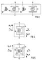
- FIG. 3 shows how the measuring points 5 and 6 can preferably be arranged on the central clamping sleeve 7.
- 1 schematically shows an overall developed section of the central clamping sleeve 7 according to FIG. 1 with alternately arranged measuring points 5, 6 for the torsional stress dependent on the head friction moment M K and the compressive stress dependent on the prestressing force F V.
- two identical measuring points 5, 6 are each offset by 180 ° from one another on the circumference of the central clamping sleeve 7. While the compressive stress dependent on the prestressing force F V can act unimpeded on the measuring point 6, the measuring point 5 for the torsional stress dependent on the head friction torque M K is relieved by the relief slots 9, 10 with regard to the prestressing force F V.
- the wall thickness D of the central clamping sleeve 7 is designed accordingly in this and the following embodiments according to the invention in such a way that overloading is avoided .
- the wall thickness D in the region of the web 13 is preferably reduced to a wall thickness d in accordance with the invention.
- At least one relief slot 9 is used here for the mechanical decoupling of the measuring point 5 for the torsional stress dependent on the head friction moment M K from the compressive stress dependent on the prestressing force F V.
- two thin tongues are used 14, 15, which are subjected to alternating tensile and compressive stresses with a changing direction of rotation of a torsional stress dependent on the head friction torque M K.
- the web 13 for the measuring point 5 for the torsional stress dependent on the head friction moment M K is delimited by two rectangular relief recesses 11, 12 which are arranged approximately at right angles to the longitudinal extent of the relief slot 9 and form the thin tongues 14, 15.
- the thin tongues 14, 15 are maximally freed from the influences of the compressive stress dependent on the prestressing force F V through the relief recesses 11, 12.
- the side walls of the relief recesses 11, 12 facing the measuring point 5 for the torsional stress dependent on the head friction moment M K are designed as straight lines, and the side walls form the web 13, the wall thickness d of which in the area of the measuring point 5 for the head friction moment M K dependent torsional stress is made smaller than the remaining wall thickness D of the central clamping sleeve 7.
- the increase in the torsional deformation at the measuring point 5 for the torsional stress dependent on the head friction torque M K can additionally be achieved according to the exemplary embodiment according to FIG. 5 by a local constriction 16 in the central region of the web 13, possibly while maintaining the material thickness D, the local Constriction 16 is preferably formed by semicircular extensions in the central region of the measuring point 5 for the side wall of the relief recesses 11, 12 facing the torsional stress depending on the head friction torque M K.
- the sides facing away from the measuring point 5 for the torsional stress dependent on the head friction torque M K preferably do not extend over the length of the relief slot 9 or 10.
- FIG. 6 schematically shows a torsionally and pressure-elastic cylindrical central clamping sleeve 7 of a force / torque transducer 1, on which at least one measuring point 6 for a compressive stress dependent on the axial preload force F V is arranged, and which are coaxially surrounded by an outer sleeve 17 on which at least one measuring point 5 for a torsional stress dependent on the head friction torque M K is arranged, which is decoupled by a compression-elastic torsion-resistant membrane 18; the torsional stress dependent on the head friction torque M K is thus measured on an outer sleeve 17.
- the measuring point 5 for the torsional stress dependent on the head friction torque M K is largely decoupled from influences of the compressive stress dependent on the prestressing force F V via at least one membrane 18.
- the storage or support of the torsionally and pressure-elastic central clamping sleeve 7 takes place as described above in relation to FIG. 1 in a housing (not shown).
- the measurement of a bending stress dependent on the total tightening torque M A also takes place on the flexible arms 28, 29, which are integrally formed on the second, preferably rectangular, flange 23 of the central clamping sleeve 7.
- the diameter of the hole 27 in the base plate 16 is larger than that of the central clamping sleeve 7 and smaller than the edge length of the second, preferably rectangular, approximately square flange 23.
- the base plate 26 is supported on its side facing the flexible arms 28, 29 the outer sleeve 17 on the flange 23 and forms a particularly play-free connection in the support area.
- the measured variable or the measured value for the torsional stress dependent on the head friction torque M K is derived via this connection into the measuring point 4 for the total tightening torque M A. The total torque is therefore not supported via the central clamping sleeve 7, but is diverted past it directly into the housing via the two flexible arms 28, 29.
- the outer sleeve 17 In the area of the measuring point 5 for the torsional stress dependent on the head friction torque M K , the outer sleeve 17 has a smaller thickness d than in the area which extends from the measuring point 5 for the torsional stress dependent on the head frictional moment M K.
- the circular membrane 18 has at least one circumferential bead 19, which largely minimizes crosstalk of the pretensioning force F V into the measuring point 5 for the torsional stress dependent on the head friction torque M K.
- a second one compression elastic torsional rigid circular membrane 18 between the outer Sleeve 17 and flange 23 may be attached, which is like a lid between one circular, formed on the outer sleeve 17, inner flange 25 and the second flange 23 extends.
- a further mechanical decoupling of the measuring point 5 for the torsional stress dependent on the head friction moment M K from the compressive stress dependent on the axial preload force F V is preferably carried out according to the invention by a suitable choice of a geometric arrangement of the measuring point 5 for the torsional stress dependent on the head friction moment M K on the outer sleeve 17 , in particular by choosing a length L of the measuring point area 5 on the outer sleeve 17, a radius R of the outer sleeve 17, and a thickness d of the outer sleeve 17 in the area of the measuring point 5 for the torsional stress dependent on the head friction torque M K , so that the influence shearings (torsional stresses) at the measuring points 6 for the compressive stress on the inner clamping sleeve 7, which is dependent on the prestressing force F V, can be considerably minimized.
- the sensitivity of the measuring points 5 for the torsional stress dependent on the head friction moment M K can be achieved, for example, by radial bores or by relief slots 9, 10 or Relief recesses 11, 12, as discussed in the description of FIGS. 1-5 above, can be increased.
- the compressive stress dependent on the prestressing force F V is measured on the central clamping sleeve 7.
- 8 schematically shows a torsionally and pressure-elastic cylindrical central clamping sleeve 7 of a force / moment transducer 1, on which at least one measuring point 6 is arranged for a compressive stress dependent on the axial preload force F V , and which is coaxial with an outer sleeve 17 is surrounded that a torsional stress dependent on the head friction torque M K acts on a pressure-elastic torsion-resistant membrane and on the outer sleeve 17 on two connecting arms 31, 32, that in particular on the side surfaces of the connecting arms 31, 32 in at least one measuring point 5a one of the head friction moment M K dependent bending stress is measurable.
- the measuring points 5a, 6 are decoupled from one another via a membrane 18 which is arranged between the flanges 22, 24 and has a circumferential bead 19.
- the outer sleeve 17 is designed as a cylinder open on both sides and has a uniform material thickness D over its entire axial length, ie the outer sleeve 17, like the membrane 18, only serves to transmit the torsional stress dependent on the head friction torque M K.
- the integral connecting arms 31, 32 which can differ in length and / or thickness from the flexible arms 28, 29, are formed on the rectangular flange 23.
- the sensitivity of the measuring point 5a for the bending stress dependent on the head friction moment M K can be optimally designed by suitably determining the length and the thickness of the connecting arms 31, 32.
- the outer sleeve 17 is connected to the arms 31, 32 of the flange 23, in particular without play, for example by screwing and / or welding.
- the strain gauges 50a in the measuring point 5a are arranged like the strain gauges 40 and 60 to one another and to the longitudinal axis 8 of the central clamping sleeve 7.
- the measurement of the head friction torque M K is thus carried out on the connecting arms 31, 32 of the second, preferably rectangular, flange 23 that are subjected to bending.
- the entire tightening torque M A applied when the screw connection is tightened is in turn applied to the flexible arms 28, 29 in the measuring points 4 measured and derived via the flexible arms 28, 29 in a housing, not shown.
- FIG. 9 schematically shows a torsionally and pressure-elastic cylindrical central clamping sleeve 7 of a force / torque transducer 1, on which at least one measuring point 6 for a compressive stress dependent on the axial preload force F V is arranged, and which are coaxially surrounded by an outer sleeve 17 is arranged on the at least one measuring point 5 for a torsional stress dependent on the head friction torque M K , which is mechanically decoupled by at least one compression-elastic torsion-resistant bellows or compensator 20, 35.
- the bellows or compensator 20, 35 has at least one shaft 21.
- a first bellows or compensator 20, known per se, with at least one shaft 21 is positively attached between the flange 22 and the outer sleeve 17 in the exemplary embodiment according to FIG. 9.
- a second bellows or compensator 35 with at least one shaft 21 connects the outer sleeve 17 to the rectangular flange 23 via a base 36.
- the connection is form-fitting, the form-fitting connection being able to be produced, for example, by screwing, jamming, gluing or welding.
- the first, preferably cylindrical, flange 22 is not integrally formed on the central clamping sleeve 7 in this exemplary embodiment, but is pushed onto the central clamping sleeve 7.
- the plug-in connection can be both loose and, for example, screwed.
- a measuring point 5 is arranged on the outer sleeve 17 for measuring the torsional stress dependent on the head friction torque M K.
- Fig. 10 shows schematically a torsionally and pressure-elastic cylindrical central clamping sleeve 7 of a force / moment transducer 1, on which at least one measuring point 5a is arranged for a compressive stress dependent on the axial prestressing force F V , this being coaxial with an outer sleeve 17 is surrounded that a torsional stress dependent on the head friction torque M K acts on at least one pressure-elastic torsion-resistant bellows or compensator 20, 35 and on the outer sleeve 17 on two connecting arms 31, 32, that in at least one measuring point 5a a function of the head friction torque M K Bending stress is measurable.
- a first bellows or compensator 20, known per se, with at least one shaft 21 is, as in the exemplary embodiment according to FIG. 9, attached in a form-fitting manner between the first flange 22 and the outer sleeve 17.
- a second bellows or compensator 35 with at least one shaft 21 connects the outer sleeve 17 directly to the connecting arms 31, 32 integrally molded on the second flange 23.
- the connection is made in a form-fitting manner, the form-fitting connection being produced, for example, by screwing, jamming, gluing or welding can.
- the cylindrical flange 22 is also, as described in FIG. 9, designed to be pluggable.
- At least one measuring point 5a preferably one measuring point 5a each, for measuring the bending stress dependent on the head friction torque M K is arranged on the two connecting arms 31, 32 arranged offset by 180 °.
- the ratio of the preload force F V or compressive stress dependent crosstalk signal (disturbance variable) to the measurement signal (useful variable) for which the torsional or bending stress dependent on the head friction torque M K can be influenced in such a way that the ratio becomes sufficiently small.
- the ratio of the measurement signals (useful variables) for the torsional or bending stress dependent on the head friction torque M K and for the compressive stress dependent on the prestressing force F V can be influenced in such a way by suitable design, in particular, of the central clamping sleeve 7 and the outer sleeve 17 that, for example, in measuring signals (useful variables) of approximately the same height can be achieved.
- a force / torque transducer 1 advantageously allow the determination of the total tightening torque M A , the head friction torque M K and the pretensioning force F V , as are required in international standards and house standards, for example of the most important automobile manufacturers.
- the head friction torque M K which is naturally difficult to measure precisely, can be detected with increased measuring accuracy and evaluated in accordance with standards.
- the thread friction torque M G can also be determined more precisely and a better assured statement about the quality and reliability of the screw connection 2, 3 is made possible.
- the invention is preferably suitable for use in quality assurance, especially in the automotive industry. Tightening torques of Self-locking nuts 3 are another area of application, as well Incoming goods inspection and research and development.
Landscapes
- Physics & Mathematics (AREA)
- General Physics & Mathematics (AREA)
- Force Measurement Appropriate To Specific Purposes (AREA)
- Details Of Spanners, Wrenches, And Screw Drivers And Accessories (AREA)
Applications Claiming Priority (2)
| Application Number | Priority Date | Filing Date | Title |
|---|---|---|---|
| DE19842231A DE19842231C1 (de) | 1998-09-15 | 1998-09-15 | Meßvorrichtung zur Bestimmung des Gesamtanzugsmoments, des Kopfreibungsmoments und der Vorspannkraft einer angezogenen Schraubverbindung |
| DE19842231 | 1998-09-15 |
Publications (3)
| Publication Number | Publication Date |
|---|---|
| EP0987532A2 true EP0987532A2 (fr) | 2000-03-22 |
| EP0987532A3 EP0987532A3 (fr) | 2001-07-18 |
| EP0987532B1 EP0987532B1 (fr) | 2008-07-02 |
Family
ID=7881045
Family Applications (1)
| Application Number | Title | Priority Date | Filing Date |
|---|---|---|---|
| EP99116864A Expired - Lifetime EP0987532B1 (fr) | 1998-09-15 | 1999-09-03 | Dispositif de mesure pour la détermination du couple de serrage total, du moment de friction d'une tête de vis et de la force de précontrainte d'une connexion à vis serrée |
Country Status (3)
| Country | Link |
|---|---|
| EP (1) | EP0987532B1 (fr) |
| AT (1) | ATE399984T1 (fr) |
| DE (2) | DE19842231C1 (fr) |
Cited By (7)
| Publication number | Priority date | Publication date | Assignee | Title |
|---|---|---|---|---|
| WO2003087748A1 (fr) * | 2002-04-12 | 2003-10-23 | Fraunhofer-Gesellschaft zur Förderung der angewandten Forschung e.V. | Dispositif pour reguler et verifier la force de tension de liaisons vissees |
| CN100430705C (zh) * | 2006-04-26 | 2008-11-05 | 宝山钢铁股份有限公司 | 管接箍车丝机刀盘预紧力检测装置 |
| FR2938060A1 (fr) * | 2008-11-06 | 2010-05-07 | Ct Tech Des Ind Mecaniques | Dispositif de mesure de contraintes d'un systeme vis/ecrou |
| FR2948454A1 (fr) * | 2009-07-21 | 2011-01-28 | Lisi Automotive Former | Agencement de mesure pour etablissement des couples et de la tension axiale d'une connexion a vis a ecrou |
| CN102175369A (zh) * | 2011-02-24 | 2011-09-07 | 上海大学 | 低温下滚动轴承的摩擦力矩测试装置 |
| EP2800959A4 (fr) * | 2011-09-02 | 2015-10-21 | Provost Dan | Assemblage intercalé entre un outil dynamométrique et un élément de fixation pour mesurer des couples et des angles de serrage |
| EP3650825A1 (fr) * | 2018-11-09 | 2020-05-13 | CiS Forschungsinstitut für Mikrosensorik GmbH | Mesure de la force operationnelle d'une composante mecanique |
Families Citing this family (9)
| Publication number | Priority date | Publication date | Assignee | Title |
|---|---|---|---|---|
| DE102011113426A1 (de) | 2011-09-15 | 2013-03-21 | Neumayer Tekfor Holding Gmbh | Mutter |
| CN103728074B (zh) * | 2013-12-09 | 2015-08-12 | 清华大学 | 一种微纳材料力学性能检测结构 |
| DE102017213801A1 (de) * | 2017-08-08 | 2019-02-14 | Zf Friedrichshafen Ag | Messvorrichtung |
| DE102018219093A1 (de) * | 2018-11-08 | 2020-05-14 | OKS Spezialschmierstoffe GmbH | Verfahren zur Prüfung eines Reibwerts einer Schraube sowie Reibwertprüfstand für Schrauben |
| CN112649137A (zh) * | 2020-12-14 | 2021-04-13 | 太原重工工程技术有限公司 | 预埋螺栓的应力监测装置 |
| CN113029405B (zh) * | 2021-02-04 | 2022-04-22 | 南京航空航天大学 | 基于光纤应变组合桥路的桨叶弯矩解耦与标定方法 |
| DE102021112871A1 (de) | 2021-05-18 | 2022-11-24 | PROMESS Gesellschaft für Montage- und Prüfsysteme mbH | Verfahren und Vorrichtung zum automatischen Vorspannen von Schraubverbindungen mit einer Stauchhülse |
| CN114018463B (zh) * | 2021-09-23 | 2023-12-19 | 东风汽车集团股份有限公司 | 一种压载式螺栓轴力标定测量装置及标定方法 |
| CN114912325B (zh) * | 2022-05-23 | 2023-03-14 | 西南交通大学 | 一种基于复合材料螺栓连接结构的预压缩量设计方法 |
Family Cites Families (6)
| Publication number | Priority date | Publication date | Assignee | Title |
|---|---|---|---|---|
| DE1277585B (de) * | 1964-07-07 | 1968-09-12 | Daimler Benz Ag | Geraet zur direkten Bestimmung des Anzugsmomentes, der axialen Spannkraft und der Torsionsspannung, ferner zur indirekten Bestimmung der Reibungskoeffizienten an den beiden Enden eines Schraubenbolzens |
| DE2352749C2 (de) * | 1973-10-20 | 1978-04-20 | Fa. Richard Bergner, 8540 Schwabach | Meßvorrichtung zum getrennten Messen des Gewindeanteils und Kopfanteils des Anziehdrehmomentes einer Schraubenverbindung |
| DE2521428C2 (de) * | 1975-05-14 | 1979-07-19 | Erichsen A M Gmbh | Meßgerät zur Bestimmung des Anzugsmomentes, des Kopf- und Gewindeanteils des Anzugsmomentes und der axialen Vorspannkraft eines Schraubenbolzens bzw. einer Schraubenverbindung |
| DE2749067A1 (de) * | 1977-11-02 | 1979-05-10 | Wilhelm Endlich | Vorrichtung zur statischen pruefung von schrauben |
| DE3408310A1 (de) * | 1984-03-07 | 1984-10-04 | Eberhard Dipl.-Ing. 6301 Wettenberg Seidel | Messvorrichtung zum getrennten messen der axialen spannkraft und des anziehdrehmomentes sowie dessen anteile aus gewinde- und kopfreibung einer schraubenverbindung ohne ueberlagerung von zug- und torsionsspannung |
| US5339696A (en) * | 1993-03-31 | 1994-08-23 | Advanced Mechanical Technology, Inc. | Bolt torque and tension transducer |
-
1998
- 1998-09-15 DE DE19842231A patent/DE19842231C1/de not_active Expired - Fee Related
-
1999
- 1999-09-03 AT AT99116864T patent/ATE399984T1/de not_active IP Right Cessation
- 1999-09-03 EP EP99116864A patent/EP0987532B1/fr not_active Expired - Lifetime
- 1999-09-03 DE DE59914797T patent/DE59914797D1/de not_active Expired - Lifetime
Cited By (8)
| Publication number | Priority date | Publication date | Assignee | Title |
|---|---|---|---|---|
| WO2003087748A1 (fr) * | 2002-04-12 | 2003-10-23 | Fraunhofer-Gesellschaft zur Förderung der angewandten Forschung e.V. | Dispositif pour reguler et verifier la force de tension de liaisons vissees |
| US7260997B2 (en) | 2002-04-12 | 2007-08-28 | Fraunhofer-Gesellschaft Zur Foerderung Der Angewandten Forschung E.V. | Device for adjusting and verifying the tension force of screwed connections |
| CN100430705C (zh) * | 2006-04-26 | 2008-11-05 | 宝山钢铁股份有限公司 | 管接箍车丝机刀盘预紧力检测装置 |
| FR2938060A1 (fr) * | 2008-11-06 | 2010-05-07 | Ct Tech Des Ind Mecaniques | Dispositif de mesure de contraintes d'un systeme vis/ecrou |
| FR2948454A1 (fr) * | 2009-07-21 | 2011-01-28 | Lisi Automotive Former | Agencement de mesure pour etablissement des couples et de la tension axiale d'une connexion a vis a ecrou |
| CN102175369A (zh) * | 2011-02-24 | 2011-09-07 | 上海大学 | 低温下滚动轴承的摩擦力矩测试装置 |
| EP2800959A4 (fr) * | 2011-09-02 | 2015-10-21 | Provost Dan | Assemblage intercalé entre un outil dynamométrique et un élément de fixation pour mesurer des couples et des angles de serrage |
| EP3650825A1 (fr) * | 2018-11-09 | 2020-05-13 | CiS Forschungsinstitut für Mikrosensorik GmbH | Mesure de la force operationnelle d'une composante mecanique |
Also Published As
| Publication number | Publication date |
|---|---|
| EP0987532B1 (fr) | 2008-07-02 |
| ATE399984T1 (de) | 2008-07-15 |
| DE59914797D1 (de) | 2008-08-14 |
| EP0987532A3 (fr) | 2001-07-18 |
| DE19842231C1 (de) | 2000-07-06 |
Similar Documents
| Publication | Publication Date | Title |
|---|---|---|
| EP0987532B1 (fr) | Dispositif de mesure pour la détermination du couple de serrage total, du moment de friction d'une tête de vis et de la force de précontrainte d'une connexion à vis serrée | |
| EP2395335B1 (fr) | Récepteur de couple doté d'un dos de profilé en U | |
| DE102016010551B3 (de) | Drehmomentsensor mit radialelastischer Momentübertragung | |
| DE2824121C2 (de) | Dehnungsmeßvorrichtung | |
| EP0012867B1 (fr) | Capteur extensomètrique par effect piézoélectrique | |
| DE102016010552B3 (de) | Drehmomentsensor mit Dichtungsmembran | |
| EP1821090A2 (fr) | Capteur de force et procédé de fabrication d'un capteur de force | |
| EP0080702A2 (fr) | Dispositif pour la mesure de force | |
| EP0465881B1 (fr) | Capteur de force avec anneau de torsion | |
| DE10163308C1 (de) | Meßvorrichtung und Sitzanordnung | |
| EP1590641A1 (fr) | Capteur de mesure avec dispositif de precontrainte | |
| EP1606596B1 (fr) | Cellule dynamometrique | |
| EP1807687B1 (fr) | Element de mesure de force | |
| EP0338325B1 (fr) | Dispositif de mesure de force du type d'anneau à torsion | |
| DE10224199A1 (de) | Kraft-Messdose | |
| DE2631698C2 (de) | Kraftmeßwandler | |
| WO2005021368A1 (fr) | Support de capteur | |
| DE1773547A1 (de) | Ringfoermige Druckkraftgeberzelle | |
| DE102004033925B4 (de) | Drehmoment-Messaufnehmer | |
| EP0483912B1 (fr) | Capteur de force de cisaillement de la forme d'un disque pour un élément de pesage | |
| EP1923684B1 (fr) | Dispositif destiné à la mesure d'une force de traction à l'intérieur d'une nappe de tissu ou d'un écheveau de fil | |
| DE4332588A1 (de) | Zugkraftmeßeinrichtung | |
| EP2892791B1 (fr) | Procédé de mesure de la tension d'une courroie | |
| EP2274590B1 (fr) | Banc d'essai à rouleaux pour des vehicules motorises | |
| DE2917966A1 (de) | Einrichtung zur messung von kraftkomponenten in gelenken |
Legal Events
| Date | Code | Title | Description |
|---|---|---|---|
| PUAI | Public reference made under article 153(3) epc to a published international application that has entered the european phase |
Free format text: ORIGINAL CODE: 0009012 |
|
| AK | Designated contracting states |
Kind code of ref document: A2 Designated state(s): AT BE CH CY DE DK ES FI FR GB GR IE IT LI LU MC NL PT SE |
|
| AX | Request for extension of the european patent |
Free format text: AL;LT;LV;MK;RO;SI |
|
| PUAL | Search report despatched |
Free format text: ORIGINAL CODE: 0009013 |
|
| AK | Designated contracting states |
Kind code of ref document: A3 Designated state(s): AT BE CH CY DE DK ES FI FR GB GR IE IT LI LU MC NL PT SE |
|
| AX | Request for extension of the european patent |
Free format text: AL;LT;LV;MK;RO;SI |
|
| RIC1 | Information provided on ipc code assigned before grant |
Free format text: 7G 01L 5/24 A, 7G 01L 3/14 B |
|
| 17P | Request for examination filed |
Effective date: 20011228 |
|
| AKX | Designation fees paid |
Free format text: AT BE CH CY DE DK ES FI FR GB GR IE IT LI LU MC NL PT SE |
|
| 17Q | First examination report despatched |
Effective date: 20040420 |
|
| APBN | Date of receipt of notice of appeal recorded |
Free format text: ORIGINAL CODE: EPIDOSNNOA2E |
|
| APBR | Date of receipt of statement of grounds of appeal recorded |
Free format text: ORIGINAL CODE: EPIDOSNNOA3E |
|
| APAF | Appeal reference modified |
Free format text: ORIGINAL CODE: EPIDOSCREFNE |
|
| APAF | Appeal reference modified |
Free format text: ORIGINAL CODE: EPIDOSCREFNE |
|
| APBT | Appeal procedure closed |
Free format text: ORIGINAL CODE: EPIDOSNNOA9E |
|
| GRAP | Despatch of communication of intention to grant a patent |
Free format text: ORIGINAL CODE: EPIDOSNIGR1 |
|
| GRAS | Grant fee paid |
Free format text: ORIGINAL CODE: EPIDOSNIGR3 |
|
| GRAA | (expected) grant |
Free format text: ORIGINAL CODE: 0009210 |
|
| AK | Designated contracting states |
Kind code of ref document: B1 Designated state(s): AT BE CH CY DE DK ES FI FR GB GR IE IT LI LU MC NL PT SE |
|
| REG | Reference to a national code |
Ref country code: GB Ref legal event code: FG4D Free format text: NOT ENGLISH |
|
| REG | Reference to a national code |
Ref country code: CH Ref legal event code: EP |
|
| REF | Corresponds to: |
Ref document number: 59914797 Country of ref document: DE Date of ref document: 20080814 Kind code of ref document: P |
|
| REG | Reference to a national code |
Ref country code: IE Ref legal event code: FG4D Free format text: LANGUAGE OF EP DOCUMENT: GERMAN |
|
| PG25 | Lapsed in a contracting state [announced via postgrant information from national office to epo] |
Ref country code: NL Free format text: LAPSE BECAUSE OF FAILURE TO SUBMIT A TRANSLATION OF THE DESCRIPTION OR TO PAY THE FEE WITHIN THE PRESCRIBED TIME-LIMIT Effective date: 20080702 |
|
| NLV1 | Nl: lapsed or annulled due to failure to fulfill the requirements of art. 29p and 29m of the patents act | ||
| PG25 | Lapsed in a contracting state [announced via postgrant information from national office to epo] |
Ref country code: PT Free format text: LAPSE BECAUSE OF FAILURE TO SUBMIT A TRANSLATION OF THE DESCRIPTION OR TO PAY THE FEE WITHIN THE PRESCRIBED TIME-LIMIT Effective date: 20081202 Ref country code: ES Free format text: LAPSE BECAUSE OF FAILURE TO SUBMIT A TRANSLATION OF THE DESCRIPTION OR TO PAY THE FEE WITHIN THE PRESCRIBED TIME-LIMIT Effective date: 20081013 |
|
| PG25 | Lapsed in a contracting state [announced via postgrant information from national office to epo] |
Ref country code: FI Free format text: LAPSE BECAUSE OF FAILURE TO SUBMIT A TRANSLATION OF THE DESCRIPTION OR TO PAY THE FEE WITHIN THE PRESCRIBED TIME-LIMIT Effective date: 20080702 |
|
| REG | Reference to a national code |
Ref country code: IE Ref legal event code: FD4D |
|
| BERE | Be: lapsed |
Owner name: TEST G.M.B.H. Effective date: 20080930 |
|
| PG25 | Lapsed in a contracting state [announced via postgrant information from national office to epo] |
Ref country code: MC Free format text: LAPSE BECAUSE OF NON-PAYMENT OF DUE FEES Effective date: 20080930 Ref country code: IE Free format text: LAPSE BECAUSE OF FAILURE TO SUBMIT A TRANSLATION OF THE DESCRIPTION OR TO PAY THE FEE WITHIN THE PRESCRIBED TIME-LIMIT Effective date: 20080702 Ref country code: DK Free format text: LAPSE BECAUSE OF FAILURE TO SUBMIT A TRANSLATION OF THE DESCRIPTION OR TO PAY THE FEE WITHIN THE PRESCRIBED TIME-LIMIT Effective date: 20080702 |
|
| REG | Reference to a national code |
Ref country code: CH Ref legal event code: PL |
|
| PLBE | No opposition filed within time limit |
Free format text: ORIGINAL CODE: 0009261 |
|
| STAA | Information on the status of an ep patent application or granted ep patent |
Free format text: STATUS: NO OPPOSITION FILED WITHIN TIME LIMIT |
|
| 26N | No opposition filed |
Effective date: 20090403 |
|
| GBPC | Gb: european patent ceased through non-payment of renewal fee |
Effective date: 20081002 |
|
| PG25 | Lapsed in a contracting state [announced via postgrant information from national office to epo] |
Ref country code: BE Free format text: LAPSE BECAUSE OF NON-PAYMENT OF DUE FEES Effective date: 20080930 |
|
| PG25 | Lapsed in a contracting state [announced via postgrant information from national office to epo] |
Ref country code: IT Free format text: LAPSE BECAUSE OF FAILURE TO SUBMIT A TRANSLATION OF THE DESCRIPTION OR TO PAY THE FEE WITHIN THE PRESCRIBED TIME-LIMIT Effective date: 20080702 |
|
| PG25 | Lapsed in a contracting state [announced via postgrant information from national office to epo] |
Ref country code: LI Free format text: LAPSE BECAUSE OF NON-PAYMENT OF DUE FEES Effective date: 20080930 Ref country code: CH Free format text: LAPSE BECAUSE OF NON-PAYMENT OF DUE FEES Effective date: 20080930 Ref country code: AT Free format text: LAPSE BECAUSE OF NON-PAYMENT OF DUE FEES Effective date: 20080903 |
|
| PG25 | Lapsed in a contracting state [announced via postgrant information from national office to epo] |
Ref country code: GB Free format text: LAPSE BECAUSE OF NON-PAYMENT OF DUE FEES Effective date: 20081002 |
|
| PG25 | Lapsed in a contracting state [announced via postgrant information from national office to epo] |
Ref country code: SE Free format text: LAPSE BECAUSE OF FAILURE TO SUBMIT A TRANSLATION OF THE DESCRIPTION OR TO PAY THE FEE WITHIN THE PRESCRIBED TIME-LIMIT Effective date: 20081002 |
|
| PG25 | Lapsed in a contracting state [announced via postgrant information from national office to epo] |
Ref country code: LU Free format text: LAPSE BECAUSE OF NON-PAYMENT OF DUE FEES Effective date: 20080903 |
|
| PG25 | Lapsed in a contracting state [announced via postgrant information from national office to epo] |
Ref country code: CY Free format text: LAPSE BECAUSE OF FAILURE TO SUBMIT A TRANSLATION OF THE DESCRIPTION OR TO PAY THE FEE WITHIN THE PRESCRIBED TIME-LIMIT Effective date: 20080702 |
|
| PG25 | Lapsed in a contracting state [announced via postgrant information from national office to epo] |
Ref country code: GR Free format text: LAPSE BECAUSE OF FAILURE TO SUBMIT A TRANSLATION OF THE DESCRIPTION OR TO PAY THE FEE WITHIN THE PRESCRIBED TIME-LIMIT Effective date: 20081003 |
|
| PGFP | Annual fee paid to national office [announced via postgrant information from national office to epo] |
Ref country code: FR Payment date: 20140922 Year of fee payment: 16 |
|
| REG | Reference to a national code |
Ref country code: FR Ref legal event code: ST Effective date: 20160531 |
|
| PG25 | Lapsed in a contracting state [announced via postgrant information from national office to epo] |
Ref country code: FR Free format text: LAPSE BECAUSE OF NON-PAYMENT OF DUE FEES Effective date: 20150930 |
|
| PGFP | Annual fee paid to national office [announced via postgrant information from national office to epo] |
Ref country code: DE Payment date: 20160930 Year of fee payment: 18 |
|
| REG | Reference to a national code |
Ref country code: DE Ref legal event code: R119 Ref document number: 59914797 Country of ref document: DE |
|
| PG25 | Lapsed in a contracting state [announced via postgrant information from national office to epo] |
Ref country code: DE Free format text: LAPSE BECAUSE OF NON-PAYMENT OF DUE FEES Effective date: 20180404 |