EP0987543A2 - Monture pour echantillon de materiau particulaire - Google Patents
Monture pour echantillon de materiau particulaire Download PDFInfo
- Publication number
- EP0987543A2 EP0987543A2 EP99118255A EP99118255A EP0987543A2 EP 0987543 A2 EP0987543 A2 EP 0987543A2 EP 99118255 A EP99118255 A EP 99118255A EP 99118255 A EP99118255 A EP 99118255A EP 0987543 A2 EP0987543 A2 EP 0987543A2
- Authority
- EP
- European Patent Office
- Prior art keywords
- gas channel
- gas
- head part
- holding device
- holder
- Prior art date
- Legal status (The legal status is an assumption and is not a legal conclusion. Google has not performed a legal analysis and makes no representation as to the accuracy of the status listed.)
- Granted
Links
Images

Classifications
-
- B—PERFORMING OPERATIONS; TRANSPORTING
- B01—PHYSICAL OR CHEMICAL PROCESSES OR APPARATUS IN GENERAL
- B01L—CHEMICAL OR PHYSICAL LABORATORY APPARATUS FOR GENERAL USE
- B01L3/00—Containers or dishes for laboratory use, e.g. laboratory glassware; Droppers
- B01L3/50—Containers for the purpose of retaining a material to be analysed, e.g. test tubes
- B01L3/508—Rigid containers without fluid transport within
-
- G—PHYSICS
- G01—MEASURING; TESTING
- G01N—INVESTIGATING OR ANALYSING MATERIALS BY DETERMINING THEIR CHEMICAL OR PHYSICAL PROPERTIES
- G01N23/00—Investigating or analysing materials by the use of wave or particle radiation, e.g. X-rays or neutrons, not covered by groups G01N3/00 – G01N17/00, G01N21/00 or G01N22/00
- G01N23/20—Investigating or analysing materials by the use of wave or particle radiation, e.g. X-rays or neutrons, not covered by groups G01N3/00 – G01N17/00, G01N21/00 or G01N22/00 by using diffraction of the radiation by the materials, e.g. for investigating crystal structure; by using scattering of the radiation by the materials, e.g. for investigating non-crystalline materials; by using reflection of the radiation by the materials
- G01N23/20008—Constructional details of analysers, e.g. characterised by X-ray source, detector or optical system; Accessories therefor; Preparing specimens therefor
- G01N23/20025—Sample holders or supports therefor
Definitions
- the invention relates to a mounting device for particulate Material samples, especially a sample holder for particles with a high liquid content, such as Protein crystals.
- Protein crystallography is a method for structural analysis of proteins, in which they crystallize in a State exposed to X-ray or synchrotron radiation to draw conclusions about the molecular structure from diffraction patterns to draw. Because of the size and irregular shape of the protein molecules are protein crystals due to very little Lattice forces and a high solvent content, that range from 30% to 70%, or even up to 90%, can lie. Protein crystals are therefore unstable and characteristic Crystal sizes in the range from 0.003 mm to 1 mm limited. The instability is particularly evident in the loss the crystal structure once the crystal is at room temperature loss of solvent due to dehydration experiences.
- a holder for individual protein crystals is from R. Kiefersauer et al. in "J. Appl. Cryst.” (Volume 29, 1996, page 311 ff.).
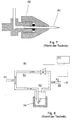
- the conventional bracket shown in Fig. 7 for the so-called “Free Mounting System” includes in particular a holding capillary 41, which is in a carrier block 42 is arranged.
- One end of the carrier capillary 41 is one Suction device (not shown) connected so that the inside the holding capillary 41 is subjected to a negative pressure can be.
- the other, protruding from the support block 42 The end forms a support for the protein crystal.
- This bracket has the advantage of individual protein crystals in the beam path to be able to manipulate the analysis device.
- a mounting device created with a support block that is not just a support element (e.g. one that works like a vacuum tweezer Holding capillary or a loop holder), but also contains at least one integrated gas channel on the end of the support element is directed.
- the gas channel opens adjacent to the support element, so that at the end a local atmosphere of gas flowing out of the gas channel or forms steam.
- the gas channel has an inner diameter that is larger than the outer diameter of the support element, wherein this is passed through the middle of the gas channel, so that the gas or steam supply through the gas channel through the now remaining cylindrical cavity between the support element and the edge of the gas channel takes place.
- the support element is surrounded by the gas channel.
- the invention Bracket device from a head part and a Insert part.
- the head part contains the gas channel, which is simultaneous a passage of the holding capillary or the loop holder forms.
- the headboard also forms a receptacle for the Insert part, so that this is axially displaceable in the head part can be fixed in a certain position. So that's the distance the end of the holding capillary or the loop holder, which is a support for the particulate material sample forms, from the mouth of the gas channel or the surface of the Carrier blocks changeable in a predetermined manner.
- a support block is by everyone given mechanical structure, the positioning and / or Movement of a holding capillary or loop holder enables.
- the holding capillary can be operated with a vacuum Hollow capillary (vacuum tweezers) or a compact, elongated, be tip-shaped component, at the end of which There is a requirement for the particulate material sample.
- the invention is therefore not based on the implementation with the vacuum tweezer assembly limited, but also with other mounting devices applicable where the particulate Material sample under action at the tip of the holding capillary of adsorption forces, electrical forces or an adhesive attached.
- the holder device is the loop holder already mentioned, that of a base part, a support part and the actual Loop exists. Loop holders of this kind are in themselves from protein crystallography Shock freezing of samples known.
- the term gas channel includes any kind of gas supply lines. There can be multiple gas channels be provided. Depending on the application, the gas carried in the gas duct comprises a gas or a vapor with a certain Content of vaporous substances that in the particulate Material sample contained liquid and / or additives correspond. For example, it can be provided that to maintain certain surface properties on the material sample a vaporous substance is passed through the gas channel which is different from the liquid or solution in the Sample differs.
- the invention has the following advantages.
- the Carrier block according to the invention with an integrated gas channel enables improved and controlled manipulability of the Sample. Adverse shadowing in the measuring system due to separate Gas nozzles are avoided.
- the gas channel allows a homogeneous and even gas flow. A complete inclusion of the A sample is guaranteed in all positions of the mounting device. It can simplify targeted changes of the sample. This affects both the supply of additives through the gas channel as well, for example the cryotechnology mentioned to protect against radiation damage in Protein crystals.
- the mounting device according to the invention can be miniaturized itself. With axially symmetrical arrangement of the support element, this is automatically centered in the gas flow.
- the structure of the mounting device according to the invention allows a simplified adjustment in relation to a measuring arrangement. The number of disruptive (e.g. scattering) components in the Measuring range is reduced. The sample held is better accessible for additional measuring methods (e.g. optical measurements).
- the invention allows a defined temperature setting for the first time in particulate material samples in which the Gas flow in the carrier block brought to a defined temperature becomes. Due to the small sample size, the sample takes immediately the gas temperature.
- the gas carried in the gas duct may also be a Inert gas can be without and from a steam additive Inert gas only depends on the temperature or application even drying function is taken over.
- the invention is described below using the example of the protein crystal holder described, but can in an analogous manner holding other particulate sample materials (in particular biological or synthetic materials as they are were mentioned above).
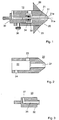
- Fig. 1 shows a mounting device according to the invention on Example of a crystal holder for Protein crystals.
- the crystal holder comprises a support block 10 with a head part 20 and an insert part 30, which individually correspondingly partially shown in Figures 2 and 3 are.
- the head part 20 is a solid component, the first Hole for the gas channel 21 and a second hole for the Insert part receptacle 22. The holes are together axially aligned.
- the gas channel 21 is over part the insert part receptacle 22 and via the side channel 23 with a Gas source (not shown) connected.
- the side channel 23 extends essentially perpendicular to the axis direction of the Gas channel 21 and the insert part receptacle 22 and opens on the gas channel side End of the insert receptacle 22 in this.
- the Headboard 20 also has a side opening 24 which of the insert part receptacle 22 leads to the outside and for receiving of the control element 36 is set up.
- the gas channel 21 runs straight from the insert receptacle 22 to the mouth on the measuring device side, tapering conically Surface of the head part 20. At the end of the gas channel 20 a mouth end 21a is formed, which on the support end 31a of the holding capillary 31 is directed.
- the insert part 30 is used as a carrier for the holding capillary 31 (see Fig. 1) provided and comprises a base part 32 and a Sealing part 33.
- the base part 32 which is shown individually in Fig. 3 is a molded part with a central bore that is provided as a capillary receptacle 35.
- the capillary uptake 35 is connected to a vacuum channel 37, which is shown in the Example essentially perpendicular to the capillary uptake 35 emerges from the insert part 30.
- the vacuum channel 37 is via a vacuum line with a pump device (not shown) connected.
- In the assembled state of the insert 30 is the holding capillary 31 in the Capillary 35.
- the inside diameter of the capillary 35 is preferably for a positive fit with the External shape of the holding capillary 31 adapted to its outer diameter. There may also be a minor game be, since the sealing part 33 is provided with an annular seal 34 is to a pressure loss from the inside of the holding capillary 31 or to prevent the capillary receptacle 35 towards the gas channel 21.
- the holding capillary 31 preferably consists of a glass tube or a micropipette (diameter approx. 1 mm) with an extended Top.
- the manufacture of the holding capillary 31 takes place analogously to the capillary production in the so-called "Patch clamp technique". After pulling out a glass tube achieved a tip diameter in the ⁇ m range. In the area of desired tip diameter, the tip is broken off and subjected to a grinding process so that a ring bearing surface as flat as possible for the protein crystal forms.
- the selected diameter of the micropipette tip is depends on the protein crystal size and is, for example around 0.1 to 0.3 mm. However, the diameter can be especially small protein crystals (up to 30 ⁇ m) be chosen smaller.
- the bracket takes place at one Negative pressure in the capillary of approx. 0.05 bar to 0.2 bar.
- the sealing part 33 is on the protrusion of the base part 32 attachable cap with an axial bore that fits the capillary 35 is aligned, and is used for positioning the holding capillary 31 and the sealing of the capillary receptacle 35. Between the sealing part 33 and the projection is the Ring seal 34 attached.
- the sealing part 33 interacts with the base part 32 as follows.
- the holding capillary 31 is through the bore of the sealing part 33 pushed and with this on the intended projection on the headboard side of the insert part 30 with the ring seal 34 (e.g. made of rubber).
- a screw connection (not shown) provided so that the sealing part 33 as a Screw cover can be attached to the projection.
- the sealing part 33 is already loose the projection sits and the holding capillary 31 through the Bore of the seated sealing part 33 is pushed.
- the ring seal is compressed.
- the sealing material lies against all adjacent surfaces of the Capillary or the insert and sealing part, so that the Capillary receptacle 35 and thus the inside of the capillary opposite the gas duct are sealed.
- the base part 32 with the holding capillary 31 attached inserted into the insert part receptacle 22 of the head part 20.
- the Insert part 30 is depending on the desired usage situation inserted into the insert receptacle 22 so that the extended Tip of the holding capillary 31 with the support for the Protein crystal remains submerged in the gas channel or around a predetermined Distance protrudes from the mouth of the gas channel 21. For example, three usage situations are provided.
- the holding capillary In the transport state, the holding capillary is in the gas channel withdrawn.
- the tip of the holding capillary 31 is from the head part covered. For example, the tip protrudes in the flow state in the range of around 1 to 5 mm from the mouth.
- the tip protrudes further from the mouth (e.g. round 20 mm).
- the insert 30 becomes in the desired position fixed with the actuator 36. Then the connection is made the vacuum line on the vacuum line channel 37 and the Gas supply on side channel 23 and the inclusion of a protein crystal (e.g. a CODH (carbon monoxide dehydroginase) crystal) from a growth solution.
- a protein crystal e.g. a CODH (carbon monoxide dehydroginase) crystal
- the mounting device according to the invention is then ready for use and will be used with the Headboard 20 (possibly with a separate bracket) or with the Insert part 30, for example, on a goniometer head X-ray or synchrotron radiation system attached.
- the holding capillary 31 can alternatively also be solid and gas-tight connected to the sealing part 33 and / or the base part 32 (e.g. glued).
- the parts of the mounting device 10 according to the invention are preferably made of corrosion-free material (e.g. Plastic) with low thermal conductivity, e.g. Delrin or Teflon (registered trademarks). However, it depends on the application other materials can also be used. The dimensioning also depends on the application.
- the crystal holder 10 is approximately on a scale of 2: 1 in FIGS. 1 to 3 shown. Deviating from the exemplary representation can change the proportion of the individual parts relative to each other , but advantageously the gas channel 21st at least 15 mm in length.
- the length of the gas channel in the head part 20 is namely preferred chosen so that the supplied in the gas solvent or Distribute additive vapors as homogeneously as possible.
- the outer shape of the head part 20 is also designed so that the respective measuring process is only minimally impaired.
- the head part 20 tapers towards the measuring device to the end of the support capillary 31 such that at the mouth of the gas channel 21, the outer diameter of the head part 20 in substantially equal to the mouth diameter of the gas channel 21 is.
- the head part 20 thus forms a truncated cone with an angle of inclination with respect to the cone axis of around 35 °.
- Fig. 1 also shows the head part 20 with an integrated Icing shield 25.
- the icing shield 25 is located between the frustoconical end of the headboard 20 and the lateral openings and channels on the rest of the cylindrical Body of the headboard 20.
- the icing shield 25 has special advantages in protecting the rear Crystal holder parts in a cryogenic treatment, in detail will be explained below.
- the temperature control device can, for example an electric heating element or a flow system for Passing heating or cooling liquids or a Peltier element include.
- a heating element can be, for example Heating wire to be in a spiral groove in the conical Surface of the head part 20 is embedded and optionally attached or covered with a silicone rubber is. It can also be connected to the gas duct 21 in the head part, preferably at the mouth end, a sensor device be provided, the a humidity and / or temperature sensor or chemical sensors.
- the sealing part 33 is integrally connected to the head part 20 and the insert part holder 22 closes on the gas channel side.
- the insert part 30 can in this embodiment be provided with an external thread that with an internal thread on the inner surface of the insert holder 22 of the head part 20 cooperates. In this case sealing with a ring seal between the screwed insert and the integral sealing part.
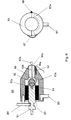
- Figures 4 and 5 show a further embodiment of a Bracket device according to the invention, also with a Crystal holder for protein crystals is provided.
- How 1 includes the crystal holder a support block 60 with a head part 70, which with others Details are also shown in Fig. 5, and an insert 67.
- the head part 70 has a through hole, the one hand the gas channel 71 and the other one Receptacle for insert 67 forms.
- the gas channel 71 is via a line system in the head part 70 and via the side channel 73 (hose connection) with a gas source, not shown connected.
- the side channel 73 goes into the head part 70 a plurality of sub-branches 72, which directly into the openings 74 open the gas channel 71.
- the head part 70 there is a heater 63 and a temperature sensor 64 integrated. This allows the head part 70 to a predetermined Setting the temperature.
- Reference numeral 65 denotes an additional insulation layer with which the temperature control is still improved. Since the branches 72 by tempered head section 70 is an optimal temperature adjustment of the gas flow regardless of any temperature fluctuations in the vicinity of the support block 60.
- the insert part 67 is the same as in the embodiment explained above designed as a carrier for the holding capillary 31.
- the Holding capillary 31 is in the insert 67 and is opposite this sealed with a seal 66 made of adhesive or wax. In this way, a negative pressure in the negative pressure channel 68 is exceeded transfer the holding capillary 31 directly to the tip 31a.
- the position of the micropipette tip 31a and thus the sample (not shown) relative to the mouth end 71a of the gas channel 71 is set with the position screw 61. If that The head part 70 and the insert part 67 can be rotated relative to one another are stored, the head of the position screw 61 runs when rotating in a corresponding groove 69 of the insert 67.
- FIG. 6 is another embodiment of the invention illustrated, in which the support element for holding the sample is formed by a loop holder.
- Fig. 6 shows in the left part again a crystal holder with a support block 80, which consists of a head part 86 and an insert part 81 is constructed.
- the head part 86 is a solid component with two axially aligned, adjacent holes that on the one hand the gas channel 86a with the mouth end 86b and on the other hand form the receptacle for the insert part 81.
- the insert 81 is because of the loop design of the receiving element also a compact component because there is no vacuum line is required.
- the insert part 81 is opposite the head part 86 rotatably supported by a needle bearing 83.
- a magnetic holder 81a At the inner end of the insert part 81 is a magnetic holder 81a, on which the base part 82 of the loop holder sits.
- the base part 82 has an inner recess, which is adapted to the outer shape of the magnet holder 81a, so that the loop holder is centered in the head part 86.
- Numeral 84 denotes a heater with which the temperature of the head part 86 and thus the gas flow from the side channel 85 to the gas channel 86a can be set.
- the temperature of the head part 86 is connected to the temperature sensor 64 supervised.
- the gas entering through side channel 85 becomes in the head part 85 again by partial branches (in the right part of 6 drawn in dashed lines) to the respective outlet opening 80a led.
- the loop 82a is connected to the Base part 82 connected.
- the position of the loop 82a relative to the Mouth end 86b of gas channel 86a is with the position screw 89 set, the head of which as described above Embodiment protrudes into a groove in the insert part 81.
- This rotatability of the headboard is an important property of the mounting device according to the invention, because one for a measurement on the sample necessary rotation supply lines to the sample head are not damaged may be.
- a particulate sample e.g. protein crystal
- a Loop 82a is known per se and has so far standard in protein crystallography for sample manipulation used for shock freezing of samples.
- Bracket designed so that the Loop holder easily removed from the head part 86 can be.
- the head part 86 is in two half shells divided, as illustrated in the right part of Figure 6.
- the half shells are connected via a joint 88 and on the opposite side clamped with a spring 87.
- the half shells By Opening the spring connection, the half shells can be opened and the loop holder by removing the Base part 82 can be removed from the magnet holder 81a.
- the Loop 82a can now be placed in a storage tank with liquid Nitrogen are transferred.
- the gas supply in the gas channel 21, 71 or 86a can for example using a moisture control system be done as is per se from the above publication by R. Kiefersauer et al. (1996) and shown in FIG. 8 is. Regarding the details of the humidity control system the publication by R. Kiefersauer et al. incorporated by reference into the following description.
- the System 50 specifically includes a gas supply 51 which is in separates a drying branch 52 and a damp branch 53. in the A computer-controlled valve V is provided for drying branch 52.
- the damp branch 53 first leads into the water and / or Additive reservoir 54 in which the supplied dry air through water at an elevated temperature.
- the air guided in the damp branch 53 then has one high moisture content (almost saturation).
- both branches are brought together again.
- a moisture sensor is located in the common gas supply channel 55 S attached, the computer control of the valve V depending from the sensor signal and predetermined humidity values controls the valve function. Via a hose connection the gas supply line 55 with the side channel 23 of the invention Bracket device connected. Instead of the sensor S can also control with a humidity sensor in the gas duct 21 of the mounting device (see above).
- the mounting device according to the invention allows implementation a new crystal transformation process that is explained below.
- the crystal transformation process includes a defined one Dehydration from the protein crystal before structural analysis. It was found for the first time that with a reproducible Dehydration from the crystal increases up to 20% the molecular order and thus a significant improvement in Analysis result can be achieved.
- One with the bracket held protein crystal is using an arrangement according to FIG. 5 corresponding to a predetermined one Time pattern of a gas flow of decreasing humidity fed. The duration of the moisture reduction depends on the crystal size in the range of 5 to 60 min. Then follows the known structural analysis.
- the crystal transformation process provides the following Benefits. There was an increase in the maximum spread angle and the signal-to-noise ratio at larger scattering angles detected. The larger scattering angles are before the transformation can only be evaluated to a limited extent. Possess after the transformation even the reflections at large angles have a sufficient amplitude.
- the crystal transformation process also leads to a reduction in the mosaicity of the crystals from conventional ones Values in the range of approx. 1.5 ° to values up to 0.4 °.
- a high level of mosaicity is disadvantageous because tilting of Many large crystallite spots occur that are mutually exclusive overlay and complicate an evaluation.
- Other parameters, of interest to crystallographers when evaluating the diffraction patterns are and when using the invention Bracket device significantly improve the so-called B-factor, the intensity of the diffraction orders and the scattering angle that occurs.
- the mounting device according to the invention can additionally or set up next to the structural analysis measurement be, the protein crystal held pulse-shaped moisture changes to cure structural defects.
- This So-called “annealing” is with the mounting device according to the invention to realize particularly advantageous because the Temperature and humidity of the gas flow in the gas channel 21 with high Reproducibility and accuracy can be set. If the mounting device according to the invention for mounting of particles from organic molecules, substances with large Water content, sugary substances, hydrated or dehydrated substances or polymeric polysaccharides are provided is, the dimension of the tip of the holding capillary 41, the Gas channel 21, the gas negative pressure in the holding capillary 31 and the composition of the supplied gas is adjusted accordingly.
- the mounting device according to the invention can therefore be modified that not a gas channel 21 in which the holding capillary 31 runs, is provided, but a plurality of gas channels. These can, for example, as in the figures 3 and 4 illustrated, at a distance from the holding capillary run through the headboard. These gas channels are preferred straight, but opposite to that formed by the holding capillary Reference axis inclined so that the mouth ends of this Gas channels directed together at the support end of the holding capillary are. According to a further modification, it is possible the mounting device according to the invention not with a multi-part support block, but with a one-piece Form carrier block in which the holding capillary and the at least one gas channel is held or formed.
Landscapes
- Chemical & Material Sciences (AREA)
- Health & Medical Sciences (AREA)
- Analytical Chemistry (AREA)
- General Health & Medical Sciences (AREA)
- Physics & Mathematics (AREA)
- Clinical Laboratory Science (AREA)
- Chemical Kinetics & Catalysis (AREA)
- Crystallography & Structural Chemistry (AREA)
- Hematology (AREA)
- Life Sciences & Earth Sciences (AREA)
- Biochemistry (AREA)
- General Physics & Mathematics (AREA)
- Immunology (AREA)
- Pathology (AREA)
- Sampling And Sample Adjustment (AREA)
- Analysing Materials By The Use Of Radiation (AREA)
Applications Claiming Priority (2)
| Application Number | Priority Date | Filing Date | Title |
|---|---|---|---|
| DE19842797A DE19842797C1 (de) | 1998-09-18 | 1998-09-18 | Probenhalterung für eine partikelförmige flüssigkeitshaltige Materialprobe |
| DE19842797 | 1998-09-18 |
Publications (3)
| Publication Number | Publication Date |
|---|---|
| EP0987543A2 true EP0987543A2 (fr) | 2000-03-22 |
| EP0987543A3 EP0987543A3 (fr) | 2001-05-09 |
| EP0987543B1 EP0987543B1 (fr) | 2002-06-26 |
Family
ID=7881404
Family Applications (1)
| Application Number | Title | Priority Date | Filing Date |
|---|---|---|---|
| EP99118255A Expired - Lifetime EP0987543B1 (fr) | 1998-09-18 | 1999-09-14 | Monture pour echantillon de materiau particulaire |
Country Status (4)
| Country | Link |
|---|---|
| US (1) | US6355217B1 (fr) |
| EP (1) | EP0987543B1 (fr) |
| AT (1) | ATE219834T1 (fr) |
| DE (2) | DE19842797C1 (fr) |
Cited By (2)
| Publication number | Priority date | Publication date | Assignee | Title |
|---|---|---|---|---|
| DE10232172A1 (de) * | 2002-07-16 | 2004-02-12 | Proteros Biostructures Gmbh | Vorrichtung und Verfahren zur Erzeugung einer definierten Umgebung für partikelförmige Proben |
| DE102013019435A1 (de) | 2013-11-20 | 2015-05-21 | Proteros Biostructures Gmbh | Verfahren und Vorrichtung zur Behandlung einer biologischen Probe, insbesondere eines Proteinkristalls |
Families Citing this family (17)
| Publication number | Priority date | Publication date | Assignee | Title |
|---|---|---|---|---|
| GB0215623D0 (en) * | 2002-07-05 | 2002-08-14 | Isis Innovation | Specimen stage |
| JP3851955B2 (ja) * | 2003-04-21 | 2006-11-29 | 大学共同利用機関法人 高エネルギー加速器研究機構 | 微小物体の捕捉装置及び捕捉方法 |
| JP4031400B2 (ja) * | 2003-07-25 | 2008-01-09 | プロテインウエーブ株式会社 | 生体高分子の結晶マウント用装置およびその製造方法 |
| US20070110901A1 (en) * | 2003-08-06 | 2007-05-17 | Proteros Biostructures Gmbh | Method for identifying weakly binding molecule fragments having ligand properties, whereby the molecule fragments are applied in the form of microdrops of a corresponding solution to the crystal |
| DE10336110B4 (de) * | 2003-08-06 | 2008-01-03 | Proteros Biostructures Gmbh | Vorrichtung und Verfahren zum Behandeln eines Proteinkristalls |
| DE10343522B4 (de) * | 2003-09-19 | 2008-09-18 | Proteros Biostructures Gmbh | Verfahren und Speichermedium zur Steuerung der Behandlung eines Kristalls mit einer Flüssigkeit |
| US7182810B2 (en) * | 2004-04-16 | 2007-02-27 | Canadian Space Agency | Protein temperature evaporation-controlled crystallization device and method thereof |
| DE102004041965B4 (de) * | 2004-08-31 | 2009-08-13 | Leica Mikrosysteme Gmbh | Vorrichtung und Verfahren zur Gefriersubstitution und Einbettung von biologischen Proben |
| US20100152895A1 (en) * | 2008-12-05 | 2010-06-17 | Zhengshan Dai | Shock freezer and system for preparing samples for analysis using the same |
| JP6001067B2 (ja) * | 2011-07-05 | 2016-10-05 | ユニバーシティ・オブ・ケープ・タウンUniversity Of Cape Town | 放射線ベースの分析装置用のサンプル保持装置 |
| US8597598B2 (en) | 2011-07-12 | 2013-12-03 | University Of Cape Town | Sample presentation device for radiation-based analytical equipment |
| EP2848924B1 (fr) * | 2013-09-11 | 2016-08-24 | Anton Paar GmbH | Chambre de mise à température pour appareil radiographique compact |
| US10359376B2 (en) * | 2016-07-20 | 2019-07-23 | Malvern Panalytical B.V. | Sample holder for X-ray analysis |
| US11921060B2 (en) * | 2018-11-22 | 2024-03-05 | Rigaku Corporation | Sample holder unit for single-crystal X-ray structure analysis apparatus |
| WO2020105723A1 (fr) * | 2018-11-23 | 2020-05-28 | 株式会社リガク | Dispositif d'occlusion d'échantillon d'analyse structurelle aux rayons x sur monocristal et procédé d'occlusion |
| JP7300744B2 (ja) * | 2018-11-23 | 2023-06-30 | 株式会社リガク | 単結晶x線構造解析用試料の吸蔵装置と吸蔵方法 |
| JP7441851B2 (ja) * | 2019-03-06 | 2024-03-01 | マイトジェン,エルエルシー | シリアルシンクロトロン結晶解析保持システム |
Family Cites Families (5)
| Publication number | Priority date | Publication date | Assignee | Title |
|---|---|---|---|---|
| US3517958A (en) * | 1968-06-17 | 1970-06-30 | Ibm | Vacuum pick-up with air shield |
| JPS60131129A (ja) | 1983-12-20 | 1985-07-12 | Matsushita Electric Ind Co Ltd | 部品吸着装置 |
| US4933548A (en) * | 1985-04-24 | 1990-06-12 | Compagnie Generale Des Matieres Nucleaires | Method and device for introducing samples for a mass spectrometer |
| US4728195A (en) * | 1986-03-19 | 1988-03-01 | Cognex Corporation | Method for imaging printed circuit board component leads |
| EP0617278A1 (fr) * | 1993-03-12 | 1994-09-28 | Orion Research, Incorporated | Connexions de tubes capillaires pour la chromatographie et l'électrophorèse |
-
1998
- 1998-09-18 DE DE19842797A patent/DE19842797C1/de not_active Expired - Fee Related
-
1999
- 1999-09-14 AT AT99118255T patent/ATE219834T1/de not_active IP Right Cessation
- 1999-09-14 EP EP99118255A patent/EP0987543B1/fr not_active Expired - Lifetime
- 1999-09-14 DE DE59901839T patent/DE59901839D1/de not_active Expired - Fee Related
- 1999-09-17 US US09/395,865 patent/US6355217B1/en not_active Expired - Lifetime
Cited By (4)
| Publication number | Priority date | Publication date | Assignee | Title |
|---|---|---|---|---|
| DE10232172A1 (de) * | 2002-07-16 | 2004-02-12 | Proteros Biostructures Gmbh | Vorrichtung und Verfahren zur Erzeugung einer definierten Umgebung für partikelförmige Proben |
| DE10232172B4 (de) * | 2002-07-16 | 2005-03-10 | Proteros Biostructures Gmbh | Vorrichtung und Verfahren zur Erzeugung einer definierten Umgebung für partikelförmige Proben |
| US7281669B2 (en) | 2002-07-16 | 2007-10-16 | Proteros Biostructures Gmbh | Apparatus and method for generating a defined environment for particle-shaped samples |
| DE102013019435A1 (de) | 2013-11-20 | 2015-05-21 | Proteros Biostructures Gmbh | Verfahren und Vorrichtung zur Behandlung einer biologischen Probe, insbesondere eines Proteinkristalls |
Also Published As
| Publication number | Publication date |
|---|---|
| US6355217B1 (en) | 2002-03-12 |
| EP0987543B1 (fr) | 2002-06-26 |
| DE59901839D1 (de) | 2002-08-01 |
| ATE219834T1 (de) | 2002-07-15 |
| DE19842797C1 (de) | 2000-01-27 |
| EP0987543A3 (fr) | 2001-05-09 |
Similar Documents
| Publication | Publication Date | Title |
|---|---|---|
| EP0987543B1 (fr) | Monture pour echantillon de materiau particulaire | |
| EP0491000B1 (fr) | Procede et dispositif pour la preparation d'un melange gazeux a des fins d'analyse et application du procede | |
| DE4142064A1 (de) | Vorrichtung zur messung von gaspermeation | |
| EP0054537A1 (fr) | Dispositif de mesure de composés volatiles dans un milieu de culture dans l'industrie de la fermentation | |
| DE4109908A1 (de) | Anordnung zur pruefung von halbleiter-wafern oder dergleichen | |
| DE2639857C2 (de) | Vorrichtung zur Untersuchung der Eigenschaften und des Züchtungsverhaltens lebender Organismen | |
| DE2363775C3 (de) | Gerät zur Untersuchung mikroskopischer Objekte durch Pyrolyse | |
| DE112020000560T5 (de) | Flüchtigkeitsaufgelöste chemische Charakterisierung von Schwebstoffen | |
| EP2325628B1 (fr) | Dispositif de thermo-analyse | |
| EP3448154B1 (fr) | Dispositif et procédé de surveillance de la température d'un échantillon biologique cryoconservé | |
| DE2459218C3 (de) | Vorrichtung zum Transferieren eines tiefgekühlten Präparatschnittes von einem Mikrotom o.dgl. zu einem Mikroskop, insbesondere Elektronenmikroskop | |
| EP1348123A1 (fr) | Procede d'analyse permettant la detection de motifs de repartition spatiale d'oligo-elements, et dispositif servant a mettre en oeuvre le procede | |
| EP2446253B1 (fr) | Procédé et dispositif pour déterminer l'adsorption d'un gaz sur des matériaux | |
| DE69907716T2 (de) | Vorrichtung und verfahren zur untersuchung von festkörpereigenschaften durch inverse-chromatographie | |
| DE112015001149T5 (de) | Kryostationssystem | |
| DE102004006650A1 (de) | Verfahren und Vorrichtung zur Bestimmung der Permeationsrate von Gasen und Dämpfen | |
| DE2907701A1 (de) | Verfahren und vorrichtung zur probeentnahme aus dem oberen teil eines raumes | |
| DE102010022016A1 (de) | Vorrichtung zur Durchführung einer Probenvorbereitung | |
| DE2708069A1 (de) | Verfahren und vorrichtung zum durchfuehren einer spektralanalyse | |
| DE3220619C2 (de) | Vorrichtung zur Handhabung von Dünnschnitten, insbesondere Kryoschnitten, und Verfahren zur Gefriertrocknung solcher Dünnschnitte | |
| DE2331284A1 (de) | Verfahren und einrichtung zur bestimmung der dichte eines gases | |
| AT524605A1 (de) | Verfahren zur Herstellung eines Einkristalls | |
| DE3211533A1 (de) | Sauerstoffmesssonde | |
| DE102008007318B4 (de) | Verfahren und Vorrichtung zur Bestimmung des Feuchtigkeitsgehaltes eines Gases | |
| DE10209427B4 (de) | Probengefäß zur Analyse von Schmelzen |
Legal Events
| Date | Code | Title | Description |
|---|---|---|---|
| PUAI | Public reference made under article 153(3) epc to a published international application that has entered the european phase |
Free format text: ORIGINAL CODE: 0009012 |
|
| AK | Designated contracting states |
Kind code of ref document: A2 Designated state(s): AT BE CH CY DE DK ES FI FR GB GR IE IT LI LU MC NL PT SE |
|
| AX | Request for extension of the european patent |
Free format text: AL;LT;LV;MK;RO;SI |
|
| PUAL | Search report despatched |
Free format text: ORIGINAL CODE: 0009013 |
|
| AK | Designated contracting states |
Kind code of ref document: A3 Designated state(s): AT BE CH CY DE DK ES FI FR GB GR IE IT LI LU MC NL PT SE |
|
| AX | Request for extension of the european patent |
Free format text: AL;LT;LV;MK;RO;SI |
|
| RIC1 | Information provided on ipc code assigned before grant |
Free format text: 7G 01N 23/20 A, 7G 01N 23/223 B, 7B 01L 3/02 B, 7H 01J 49/04 B |
|
| 17P | Request for examination filed |
Effective date: 20010801 |
|
| 17Q | First examination report despatched |
Effective date: 20010918 |
|
| AKX | Designation fees paid |
Free format text: AT BE CH CY DE DK ES FI FR GB GR IE IT LI LU MC NL PT SE |
|
| GRAG | Despatch of communication of intention to grant |
Free format text: ORIGINAL CODE: EPIDOS AGRA |
|
| RTI1 | Title (correction) |
Free format text: HOLDER FOR PARTICLE SHAPED SAMPLE |
|
| GRAG | Despatch of communication of intention to grant |
Free format text: ORIGINAL CODE: EPIDOS AGRA |
|
| GRAH | Despatch of communication of intention to grant a patent |
Free format text: ORIGINAL CODE: EPIDOS IGRA |
|
| GRAH | Despatch of communication of intention to grant a patent |
Free format text: ORIGINAL CODE: EPIDOS IGRA |
|
| GRAA | (expected) grant |
Free format text: ORIGINAL CODE: 0009210 |
|
| AK | Designated contracting states |
Kind code of ref document: B1 Designated state(s): AT BE CH CY DE DK ES FI FR GB GR IE IT LI LU MC NL PT SE |
|
| PG25 | Lapsed in a contracting state [announced via postgrant information from national office to epo] |
Ref country code: NL Free format text: LAPSE BECAUSE OF FAILURE TO SUBMIT A TRANSLATION OF THE DESCRIPTION OR TO PAY THE FEE WITHIN THE PRESCRIBED TIME-LIMIT Effective date: 20020626 Ref country code: IT Free format text: LAPSE BECAUSE OF FAILURE TO SUBMIT A TRANSLATION OF THE DESCRIPTION OR TO PAY THE FEE WITHIN THE PRESCRIBED TIME-LIMIT;WARNING: LAPSES OF ITALIAN PATENTS WITH EFFECTIVE DATE BEFORE 2007 MAY HAVE OCCURRED AT ANY TIME BEFORE 2007. THE CORRECT EFFECTIVE DATE MAY BE DIFFERENT FROM THE ONE RECORDED. Effective date: 20020626 Ref country code: IE Free format text: LAPSE BECAUSE OF FAILURE TO SUBMIT A TRANSLATION OF THE DESCRIPTION OR TO PAY THE FEE WITHIN THE PRESCRIBED TIME-LIMIT Effective date: 20020626 Ref country code: GR Free format text: LAPSE BECAUSE OF FAILURE TO SUBMIT A TRANSLATION OF THE DESCRIPTION OR TO PAY THE FEE WITHIN THE PRESCRIBED TIME-LIMIT Effective date: 20020626 Ref country code: FI Free format text: LAPSE BECAUSE OF FAILURE TO SUBMIT A TRANSLATION OF THE DESCRIPTION OR TO PAY THE FEE WITHIN THE PRESCRIBED TIME-LIMIT Effective date: 20020626 |
|
| REF | Corresponds to: |
Ref document number: 219834 Country of ref document: AT Date of ref document: 20020715 Kind code of ref document: T |
|
| REG | Reference to a national code |
Ref country code: GB Ref legal event code: FG4D Free format text: NOT ENGLISH |
|
| REG | Reference to a national code |
Ref country code: CH Ref legal event code: EP |
|
| REG | Reference to a national code |
Ref country code: IE Ref legal event code: FG4D Free format text: GERMAN |
|
| REF | Corresponds to: |
Ref document number: 59901839 Country of ref document: DE Date of ref document: 20020801 |
|
| PG25 | Lapsed in a contracting state [announced via postgrant information from national office to epo] |
Ref country code: LU Free format text: LAPSE BECAUSE OF NON-PAYMENT OF DUE FEES Effective date: 20020914 Ref country code: AT Free format text: LAPSE BECAUSE OF NON-PAYMENT OF DUE FEES Effective date: 20020914 |
|
| PG25 | Lapsed in a contracting state [announced via postgrant information from national office to epo] |
Ref country code: PT Free format text: LAPSE BECAUSE OF FAILURE TO SUBMIT A TRANSLATION OF THE DESCRIPTION OR TO PAY THE FEE WITHIN THE PRESCRIBED TIME-LIMIT Effective date: 20020926 Ref country code: DK Free format text: LAPSE BECAUSE OF FAILURE TO SUBMIT A TRANSLATION OF THE DESCRIPTION OR TO PAY THE FEE WITHIN THE PRESCRIBED TIME-LIMIT Effective date: 20020926 |
|
| PG25 | Lapsed in a contracting state [announced via postgrant information from national office to epo] |
Ref country code: CY Free format text: LAPSE BECAUSE OF FAILURE TO SUBMIT A TRANSLATION OF THE DESCRIPTION OR TO PAY THE FEE WITHIN THE PRESCRIBED TIME-LIMIT Effective date: 20020930 Ref country code: BE Free format text: LAPSE BECAUSE OF NON-PAYMENT OF DUE FEES Effective date: 20020930 |
|
| GBT | Gb: translation of ep patent filed (gb section 77(6)(a)/1977) |
Effective date: 20020910 |
|
| REG | Reference to a national code |
Ref country code: CH Ref legal event code: NV Representative=s name: R. A. EGLI & CO. PATENTANWAELTE |
|
| NLV1 | Nl: lapsed or annulled due to failure to fulfill the requirements of art. 29p and 29m of the patents act | ||
| ET | Fr: translation filed | ||
| PG25 | Lapsed in a contracting state [announced via postgrant information from national office to epo] |
Ref country code: ES Free format text: LAPSE BECAUSE OF FAILURE TO SUBMIT A TRANSLATION OF THE DESCRIPTION OR TO PAY THE FEE WITHIN THE PRESCRIBED TIME-LIMIT Effective date: 20021220 |
|
| REG | Reference to a national code |
Ref country code: IE Ref legal event code: FD4D Ref document number: 0987543E Country of ref document: IE |
|
| BERE | Be: lapsed |
Owner name: *MAX-PLANCK-GESELLSCHAFT ZUR FORDERUNG DER WISSENS Effective date: 20020930 |
|
| PG25 | Lapsed in a contracting state [announced via postgrant information from national office to epo] |
Ref country code: MC Free format text: LAPSE BECAUSE OF NON-PAYMENT OF DUE FEES Effective date: 20030401 Ref country code: DE Free format text: LAPSE BECAUSE OF NON-PAYMENT OF DUE FEES Effective date: 20030401 |
|
| PLBE | No opposition filed within time limit |
Free format text: ORIGINAL CODE: 0009261 |
|
| STAA | Information on the status of an ep patent application or granted ep patent |
Free format text: STATUS: NO OPPOSITION FILED WITHIN TIME LIMIT |
|
| 26N | No opposition filed |
Effective date: 20030327 |
|
| PGFP | Annual fee paid to national office [announced via postgrant information from national office to epo] |
Ref country code: GB Payment date: 20060913 Year of fee payment: 8 |
|
| PGFP | Annual fee paid to national office [announced via postgrant information from national office to epo] |
Ref country code: CH Payment date: 20061221 Year of fee payment: 8 |
|
| PGFP | Annual fee paid to national office [announced via postgrant information from national office to epo] |
Ref country code: SE Payment date: 20060907 Year of fee payment: 8 |
|
| PG25 | Lapsed in a contracting state [announced via postgrant information from national office to epo] |
Ref country code: SE Free format text: LAPSE BECAUSE OF NON-PAYMENT OF DUE FEES Effective date: 20070915 |
|
| REG | Reference to a national code |
Ref country code: CH Ref legal event code: PL |
|
| EUG | Se: european patent has lapsed | ||
| GBPC | Gb: european patent ceased through non-payment of renewal fee |
Effective date: 20070914 |
|
| PG25 | Lapsed in a contracting state [announced via postgrant information from national office to epo] |
Ref country code: LI Free format text: LAPSE BECAUSE OF NON-PAYMENT OF DUE FEES Effective date: 20070930 Ref country code: CH Free format text: LAPSE BECAUSE OF NON-PAYMENT OF DUE FEES Effective date: 20070930 |
|
| REG | Reference to a national code |
Ref country code: FR Ref legal event code: ST Effective date: 20080531 |
|
| PG25 | Lapsed in a contracting state [announced via postgrant information from national office to epo] |
Ref country code: FR Free format text: LAPSE BECAUSE OF NON-PAYMENT OF DUE FEES Effective date: 20071001 |
|
| PGFP | Annual fee paid to national office [announced via postgrant information from national office to epo] |
Ref country code: FR Payment date: 20060928 Year of fee payment: 8 |
|
| PG25 | Lapsed in a contracting state [announced via postgrant information from national office to epo] |
Ref country code: GB Free format text: LAPSE BECAUSE OF NON-PAYMENT OF DUE FEES Effective date: 20070914 |