EP0987561B1 - Radar à holographie - Google Patents
Radar à holographie Download PDFInfo
- Publication number
- EP0987561B1 EP0987561B1 EP99118187A EP99118187A EP0987561B1 EP 0987561 B1 EP0987561 B1 EP 0987561B1 EP 99118187 A EP99118187 A EP 99118187A EP 99118187 A EP99118187 A EP 99118187A EP 0987561 B1 EP0987561 B1 EP 0987561B1
- Authority
- EP
- European Patent Office
- Prior art keywords
- antennas
- reception
- transmission
- reception antennas
- holographic radar
- Prior art date
- Legal status (The legal status is an assumption and is not a legal conclusion. Google has not performed a legal analysis and makes no representation as to the accuracy of the status listed.)
- Expired - Lifetime
Links
- 230000005540 biological transmission Effects 0.000 claims description 90
- 230000005855 radiation Effects 0.000 claims description 11
- 238000001514 detection method Methods 0.000 claims description 8
- 230000001678 irradiating effect Effects 0.000 claims description 2
- 230000035945 sensitivity Effects 0.000 description 8
- 238000010586 diagram Methods 0.000 description 3
- 230000015556 catabolic process Effects 0.000 description 2
- 230000000052 comparative effect Effects 0.000 description 2
- 238000006731 degradation reaction Methods 0.000 description 2
- 238000012544 monitoring process Methods 0.000 description 2
- 230000002730 additional effect Effects 0.000 description 1
- 230000002238 attenuated effect Effects 0.000 description 1
- 230000001427 coherent effect Effects 0.000 description 1
- 230000002349 favourable effect Effects 0.000 description 1
- 238000000034 method Methods 0.000 description 1
- 230000008054 signal transmission Effects 0.000 description 1
Images


Classifications
-
- G—PHYSICS
- G01—MEASURING; TESTING
- G01S—RADIO DIRECTION-FINDING; RADIO NAVIGATION; DETERMINING DISTANCE OR VELOCITY BY USE OF RADIO WAVES; LOCATING OR PRESENCE-DETECTING BY USE OF THE REFLECTION OR RERADIATION OF RADIO WAVES; ANALOGOUS ARRANGEMENTS USING OTHER WAVES
- G01S13/00—Systems using the reflection or reradiation of radio waves, e.g. radar systems; Analogous systems using reflection or reradiation of waves whose nature or wavelength is irrelevant or unspecified
- G01S13/88—Radar or analogous systems specially adapted for specific applications
- G01S13/89—Radar or analogous systems specially adapted for specific applications for mapping or imaging
-
- G—PHYSICS
- G01—MEASURING; TESTING
- G01S—RADIO DIRECTION-FINDING; RADIO NAVIGATION; DETERMINING DISTANCE OR VELOCITY BY USE OF RADIO WAVES; LOCATING OR PRESENCE-DETECTING BY USE OF THE REFLECTION OR RERADIATION OF RADIO WAVES; ANALOGOUS ARRANGEMENTS USING OTHER WAVES
- G01S13/00—Systems using the reflection or reradiation of radio waves, e.g. radar systems; Analogous systems using reflection or reradiation of waves whose nature or wavelength is irrelevant or unspecified
- G01S13/02—Systems using reflection of radio waves, e.g. primary radar systems; Analogous systems
-
- G—PHYSICS
- G01—MEASURING; TESTING
- G01S—RADIO DIRECTION-FINDING; RADIO NAVIGATION; DETERMINING DISTANCE OR VELOCITY BY USE OF RADIO WAVES; LOCATING OR PRESENCE-DETECTING BY USE OF THE REFLECTION OR RERADIATION OF RADIO WAVES; ANALOGOUS ARRANGEMENTS USING OTHER WAVES
- G01S7/00—Details of systems according to groups G01S13/00, G01S15/00, G01S17/00
- G01S7/02—Details of systems according to groups G01S13/00, G01S15/00, G01S17/00 of systems according to group G01S13/00
- G01S7/35—Details of non-pulse systems
-
- H—ELECTRICITY
- H01—ELECTRIC ELEMENTS
- H01Q—ANTENNAS, i.e. RADIO AERIALS
- H01Q3/00—Arrangements for changing or varying the orientation or the shape of the directional pattern of the waves radiated from an antenna or antenna system
- H01Q3/24—Arrangements for changing or varying the orientation or the shape of the directional pattern of the waves radiated from an antenna or antenna system varying the orientation by switching energy from one active radiating element to another, e.g. for beam switching
Definitions
- the present invention relates to a holographic radar having a plurality of reception antennas for receiving reflection waves of a radio wave transmitted from transmission antennas, and especially to such a holographic radar in which radar signals are acquired in a time-shared manner by the connections of the plurality of reception antennas switched in sequence to a receiver.
- a single transmission antenna is provided to transmit a radio wave, with a plurality of reception antennas receiving reflection waves of the radio wave transmitted.
- the plurality of reception antennas are then connected via a switch to a single receiver.
- the plurality of reception antennas are switched in sequence for the connection to the receiver so that radar signals obtained for each reception antenna can be acquired in a time-shared manner.
- this example includes a reception antenna array consisting of multiple reception antennas, which are associated with a single receiver in groups of four antennas.
- the radio wave used herein are in a high-frequency band of, for example, 76 GHz. For this reason, signals handled in the transmission line from the reception antennas to the receiver are signals belonging to the high-frequency band.
- the switch for switching such high-frequency signals typically has two or three throw.
- Switches are often required for the switching of four or more reception antennas.
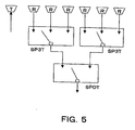
- multi-switching can be implemented through a combination of single pole double throw (SPDT) switches or single pole triple throw (SP3T) switches in a tournament form.
- Unit switches used therein can be planar circuit type high-frequency switches such as MMICs (microwave monolithic integrated circuits) or HICs (hybrid integrated circuits).
- switches in multi-stage connection may cause a degradation in reception sensitivity since a signal will be attenuated every time it passes through each switch.
- US 3,685,051 discloses a technique for forming and interference pattern image of an object which is irradiated with coherent wave energy.
- the present invention provides a holographic radar having a plurality of reception antennas for receiving reflection waves of a radio wave transmitted from transmission antennas, the connection of the plurality of reception antennas to a receiver being switched in sequence to thereby acquire radar signals in a time-shared manner, wherein a plurality of transmission antennas are provided and switched in sequence for the transmission of the radio wave.
- the number of reception antennas can be reduced by switching the plurality of transmission antennas. It is thus possible to reduce the number of switches for switching the reception antennas and to enhance the reception sensitivity. Furthermore, the reduction in the number of the antennas and switches leads to lowered production costs of the device.
- FIG. 1 there is depicted a configuration of the embodiment of a holographic radar in accordance with the present invention.
- An oscillator 10 oscillates in a high-frequency band of, for example, 76 GHz.
- a switch 14 on the transmitter side is connected via a power divider 12 to the oscillator 10.
- the switch 14 is a single pole triple throw (SP3T) switch whose outputs are coupled to three transmission antennas T1, T2, T3. Switching by the switch 14 therefore allows the high frequency signals from the oscillator 10 to be fed to the transmission antennas T1, T2, T3 in a time-shared manner.
- the high frequency signals from the oscillator 10 are thus transmitted in sequence from the transmission antennas T1, T2, T3 in a time-shared manner.
- these transmission antennas have identical radiation pattern, which preferably is the one capable of irradiating a radio wave to the entire detection region.
- a switch 16 on the receiver side is coupled to the reception antennas R1, R2.
- the switch 16 is a single pole double throw (SPDT) switch to which outputs are coupled the two reception antennas R1, R2.
- a mixer 18 is coupled to the single output of the switch 16. Switching by the switch 16 therefore allows reception signals received by the two reception antennas R1, R2 to be fed to the mixer 18 in a time-shared manner.
- these reception antennas have identical radiation pattern, which preferably is the one capable of receiving reflected waves from the entire detection region.
- the transmission antennas T1 to T3 and the reception antennas R1, R2 lie in alignment on the same plane and on the same straight line. With this alignment, a finished product can be made with a simple shape, allowing production costs to be reduced. Further, in considering application of these antennas to an automotive radar, or the like, the radar can be configured so that their overall shape is favorable to being mounted on an automobile. It is, however, to be noted that those antennas need not necessarily be arranged on the same straight line and on the same plane.
- the mixer 18 accepts some of transmission high frequency signals from the power divider 12. The mixer 18 therefore acquires modulated signals in the form of superposition of reception high frequency signals reflected by the target on the transmission high frequency signals.
- An analog-to-digital converter 20 is coupled to the mixer 18 to convert the modulated signals fed from the mixer 18 into digital signals.
- a signal processing circuit 22 is coupled to the analog-to-digital converter 20 to receive the modulated signals in the form of digital signals. The signal processing circuit 22 executes data processing of the thus received modulated signals to acquire desired information such as the distance to the target, relative velocity, etc.
- Lt 2Lr is given where Lr is the interval between the reception antennas R1 and R2, and Lt is the respective intervals between the transmission antennas T1, T2 and T3. That is, the interval Lt of the transmission antennas is equal to the interval Lr of the reception antennas multiplied by the number of reception antennas, which is 2 in the present embodiment.
- Switching of the transmission antennas T1, T2, T3 and the reception antennas R1, R2 is carried out in conformity with the sequence depicted in Fig. 2.
- Fig. 2 illustrates the relationship in pairs between the transmission antennas T1, T2, T3 and the reception antennas R1, R2, which is utilized in time-sharing when the transmission/reception is carried out with the switching of the transmission antennas T1, T2, T3 and the reception antennas R1, R2.
- the pairs of the transmission antennas T1, T2, T3 and the reception antennas R1, R2 vary in the sequence of (1) T1, R1, (2) T1, R2, (3) T2, R1, (4) T2, R2, (5) T3, R1 and (6) T3, R2.
- reception signals received by the reception antennas R1, R2 upon the transmission from the transmission antenna T2 are expected to be identical to ones obtained when the transmission antenna T2 is moved to the position of the transmission antenna T1 with the antennas R1, R2 being translated by Lt in the opposite direction.
- reception signals received by the reception antennas R1, R2 upon the transmission of the transmission antenna T3 are expected to be identical to ones obtained when the transmission antenna T3 is moved to the position of the transmission antenna T1 with the antennas R1, R2 being translated by 2Lt.
- Fig. 3 illustrate the time-sequential relationship in pairs between the transmission antennas and the reception antennas, with the positional relationship in the direction in which the antennas are arrayed.
- reception signals will become equivalent to ones obtained when six reception antennas are arranged for a single transmission antenna, as can be seen in Fig. 4.
- two-stage switching configuration must be employed which consists of two SP3T switches and one SPDT switch.
- the switch 14 is required on the transmitter side whereas provision of the switch 16 in a single stage will suffice for the switching of the reception antennas R1, R2. This may result in a reduction in attenuation of the reception signals through the switches.
- the switch 14 on the transmitter side may subject transmission signals to any attenuation although this will be negligible if the transmission signals have a sufficient signal strength.
- the number of the transmission antennas is larger than the reception antennas. Accordingly, the reception antenna and the switch are connected through a shorter line compared to a unit wherein there are more reception antennas than transmission antennas, and attenuation on the receiver side can thus be reduced. Also, since the number of time of switching in the switch 16 on the receiver side becomes smaller than that in the switch 14 on the transmitter side, and a less number of times of switching results in a less attenuation, it is possible to reduce loss on the receiver side. As a result, reception sensitivity on the receiver side can be improved.
- this embodiment employs by way of example three transmission antennas and two reception antennas, the number of these antennas may further be increased. It is to be appreciated that four or more antennas on each side would require a multi-stage configuration of the switches in tournament form.
- the transmission antennas T1, T2, T3 and the reception antennas R1, R2 are shown to be aligned on the same line, they do not necessarily have to be arrayed as such.
- the intervals between the transmission antennas and the reception antennas could be any arbitrary ones.
- the intervals between the transmission antennas T1, T2 and T3 could be ones except the above-described values. In such a case, the reception signals may be subjected to any calculations for compensating for positional changes.
- the transmission antennas T1, T2, T3 have the same radiation pattern, so that three reception signals received at each reception antennas R1 and R2 for three transmission antennas becomes equal to those received at three positions for a single transmission antenna. Further, it is preferable that the reception antennas R1, R2 have the same radiation pattern, so that reception signals by respective receptions antennas R1, R2 can be compared with one another intact. It should be noted that when the transmission antennas T1, T2, T3 do not have the same radiation pattern or when the reception antennas R1, R2 do not have the same radiation pattern, any calculations for compensating the difference may be applied.
- transmission antennas T1, T2, T3 are able to irradiate a radio wave to the entire detection region. This makes it possible to obtain reflection waves from any target within the detection region. Further, it is preferable that each reception antenna R1, R2 be able to receive a radio wave from the entire detection region. This makes it possible to reliably receive reflection waves from any target within the detection region, regardless of which reception antenna is selected.
- reception antennas R1, R2 be switched during a period when a single transmission antenna T1, T2, or T3 is selected. This makes it easier to maintain a longer period with a single transmission antenna being selected. As a certain amount of time is required for radio wave from a transmission antenna to be reflected by a target and then received by a reception antenna, switching of transmission antennas too early can make it difficult to determine from which transmission antenna the received reflection waves originated. Switching reception antennas while a single transmission antennas is selected can make easier processing with a reception signal.
- Such a holographic radar would be suitable e.g., for being mounted on automobile to monitor the forward vehicles.
- switchable use of a plurality of transmission antennas makes it possible to reduce the number of reception antennas. This results in a reduction in the number of switches for switching the reception antennas, contributing to an enhanced reception sensitivity. This also leads to a reduction in the number of antennas and switches, contributing to a curtailed production cost of the device.
- n and n are the number of transmission antennas and the number of reception antennas, respectively.
- the same functions can be implemented as those obtained when the number of reception antennas is n x m with the number of the transmission antennas being 1.
- the number of the reception antennas can be reduced. This in turn results in a reduction in the number of switches for switching the reception antennas whereby it is possible to achieve a reduced attenuation in the reception signals and to provide an improved reception sensitivity. It is further possible to reduce the total number of the antennas and switches to thereby accomplish a reduction in costs of the device.
- the above transmission antennas and the reception antennas be aligned on the same plane, and especially that they be arrayed in the same line.
- Automotive radars are usually required to have monitoring areas narrower (of the order of 3 to 4 degrees) in the vertical direction but wider (of the order of 20 degrees or more) in the horizontal direction with respect to the position where a target to be detected lies.
- the radiation patterns of the transmission and reception antennas are preferably designed to conform to their respective monitoring areas.
- each antenna tends to have an aperture contour longer in the vertical direction but shorter in the horizontal direction.
- the interval between the transmission antennas depend on the number of the reception antennas, and particularly preferably, the interval between the transmission antennas be equal to the product of the interval between the reception antennas and the number of the reception antennas. Such a configuration ensures the acquisition of reception signals similar to those obtained by the radars having reception antennas arrayed with equal intervals, facilitating processing of the reception signals.
- the number of the reception antennas be equal to or less than the number of the transmission antennas.
- attenuation on the transmitter side induced by the switching and the connections between the switches and the antennas, may become larger than that on the receiver side. Nevertheless, such signal attenuation on the transmitter side will be substantially negligible as long as sufficient strength is conferred on the transmission signals.
- the reception sensitivity can be enhanced as a whole.
Landscapes
- Engineering & Computer Science (AREA)
- Remote Sensing (AREA)
- Radar, Positioning & Navigation (AREA)
- Physics & Mathematics (AREA)
- Computer Networks & Wireless Communication (AREA)
- General Physics & Mathematics (AREA)
- Electromagnetism (AREA)
- Radar Systems Or Details Thereof (AREA)
Claims (13)
- Radar holographique comprenant :caractérisé en ce que la distance entre les antennes voisines de la pluralité d'antennes d'émission (T1, T2, T3) dépend du nombre total de la pluralité d'antennes de réception (R1, R2).une pluralité d'antennes d'émission (T1, T2, T3) destinées à émettre une onde radio conformément à des signaux radio devant être appliqués,un commutateur (14) du côté de l'émetteur, destiné à commuter les signaux d'émission et à les appliquer sur la pluralité d'antennes d'émission (T1, T2, T3) selon une séquence prédéterminée,une pluralité d'antennes de réception (R1, R2) destinées à recevoir les ondes réfléchies à partir de l'onde radio émise de la pluralité d'antennes d'émission (T1, T2, T3), etun commutateur (16) du côté du récepteur, destiné à commuter en séquence les antennes de réception vers un récepteur,la pluralité d'antennes d'émission (T1, T2, T3) émettant la onde radio en temps partagé, la pluralité d'antennes de réception recevant la onde réfléchie en temps partagé,
- Radar holographique selon la revendication 1, dans lequel
la pluralité d'antennes d'émission (T1, T2, T3) et la pluralité d'antennes de réception (R1, R2) sont mises suivant un réseau sur le même plan. - Radar holographique selon la revendication 2, dans lequel
ladite pluralité d'antennes d'émission (T1, T2, T3) et ladite pluralité d'antennes de réception (R1, R2) sont mises suivant un réseau sur la même ligne. - Radar holographique selon la revendication 1, dans lequel
la distance entre des antennes voisines de la pluralité d'antennes d'émission (T1, T2, T3) est égale au produit de la distance entre des antennes voisines de la pluralité d'antennes de réception (R1, R2) et le nombre total de la pluralité d'antennes de réception (R1, R2). - Radar holographique selon la revendication 4, dans lequel
la pluralité d'antennes d'émission (T1, T2, T3) et la pluralité d'antennes de réception (R1, R2) sont mises suivant un réseau sur la même ligne. - Radar holographique selon la revendication 1, dans lequel
le nombre total de la pluralité d'antennes de réception (R1, R2) est inférieur ou égal au nombre total de la pluralité d'antennes d'émission (T1, T2, T3). - Radar holographique selon la revendication 6, dans lequel
le nombre total de la pluralité d'antennes de réception (R1, R2) est inférieur au nombre total de la pluralité d'antennes d'émission (T1, T2, T3). - Radar holographique selon la revendication 1, dans lequel
les plusieurs antennes d'émission (T1, T2, T3) présentent toutes le même diagramme de rayonnement et les plusieurs antennes de réception (R1, R2) présentent toutes le même diagramme de rayonnement. - Radar holographique selon la revendication 8, dans lequel
les plusieurs antennes d'émission (T1, T2, T3) présentent chacune un diagramme de rayonnement capable de rayonner une onde radio vers la totalité d'une région prédéterminée de détection. - Radar holographique selon la revendication 8, dans lequel
les plusieurs antennes de réception (R1, R2) présentent chacune un diagramme de rayonnement capable de recevoir une onde radio provenant de la totalité d'une région prédéterminée de détection. - Radar holographique selon la revendication 10, dans lequel
la pluralité d'antennes d'émission (T1, T2, T3) et la pluralité d'antennes de réception (R1, R2) sont mises en réseau sur la même ligne. - Radar holographique selon la revendication 1, dans lequel
les plusieurs antennes d'émission (T1, T2, T3) sont commutées en séquence selon un ordre prédéterminé et les plusieurs antennes de réception (R1, R2) sont commutées en séquence selon un ordre prédéterminé alors qu'une seule antenne d'émission (T1, T2, T3) est sélectionnée. - Radar holographique selon la revendication 12, dans lequel
la pluralité d'antennes d'émission (T1, T2, T3) et la pluralité d'antennes de réception (R1, R2) sont mises en réseau sur la même ligne.
Applications Claiming Priority (2)
| Application Number | Priority Date | Filing Date | Title |
|---|---|---|---|
| JP26013898 | 1998-09-14 | ||
| JP26013898 | 1998-09-14 |
Publications (3)
| Publication Number | Publication Date |
|---|---|
| EP0987561A2 EP0987561A2 (fr) | 2000-03-22 |
| EP0987561A3 EP0987561A3 (fr) | 2000-11-29 |
| EP0987561B1 true EP0987561B1 (fr) | 2005-12-07 |
Family
ID=17343842
Family Applications (1)
| Application Number | Title | Priority Date | Filing Date |
|---|---|---|---|
| EP99118187A Expired - Lifetime EP0987561B1 (fr) | 1998-09-14 | 1999-09-13 | Radar à holographie |
Country Status (3)
| Country | Link |
|---|---|
| US (1) | US6288672B1 (fr) |
| EP (1) | EP0987561B1 (fr) |
| DE (1) | DE69928735T2 (fr) |
Cited By (1)
| Publication number | Priority date | Publication date | Assignee | Title |
|---|---|---|---|---|
| DE102010040438A1 (de) * | 2009-09-10 | 2011-04-14 | Fujitsu Ten Ltd., Kobe-shi | Radarvorrichtung |
Families Citing this family (65)
| Publication number | Priority date | Publication date | Assignee | Title |
|---|---|---|---|---|
| JP4067456B2 (ja) * | 2003-06-09 | 2008-03-26 | 富士通テン株式会社 | レーダ装置及びその信号処理制御方法 |
| US20050084033A1 (en) * | 2003-08-04 | 2005-04-21 | Lowell Rosen | Scalable transform wideband holographic communications apparatus and methods |
| US20050031051A1 (en) * | 2003-08-04 | 2005-02-10 | Lowell Rosen | Multiple access holographic communications apparatus and methods |
| US20050100076A1 (en) * | 2003-08-04 | 2005-05-12 | Gazdzinski Robert F. | Adaptive holographic wideband communications apparatus and methods |
| US20050041757A1 (en) * | 2003-08-04 | 2005-02-24 | Lowell Rosen | Frequency-hopped holographic communications apparatus and methods |
| US20050041746A1 (en) * | 2003-08-04 | 2005-02-24 | Lowell Rosen | Software-defined wideband holographic communications apparatus and methods |
| US20050031016A1 (en) * | 2003-08-04 | 2005-02-10 | Lowell Rosen | Epoch-variant holographic communications apparatus and methods |
| JP4000103B2 (ja) * | 2003-10-09 | 2007-10-31 | 三菱電機株式会社 | 高周波スイッチ装置及び高周波スイッチ構造 |
| JP2006003303A (ja) | 2004-06-21 | 2006-01-05 | Fujitsu Ten Ltd | レーダ装置 |
| JP2006010329A (ja) * | 2004-06-22 | 2006-01-12 | Fujitsu Ten Ltd | レーダのタイミング調整方法およびタイミング自動調整機能を有するレーダ装置 |
| DE102004034429B4 (de) * | 2004-07-15 | 2009-12-24 | Augustin & Augustin GbR (vertretungsberechtigter Gesellschafter:Christian Augustin, 88709 Meersburg) | Radar Front-End |
| JP4833534B2 (ja) * | 2004-09-29 | 2011-12-07 | 富士通株式会社 | レーダ装置 |
| CN100495951C (zh) * | 2005-05-09 | 2009-06-03 | 上海原动力通信科技有限公司 | 一种动态选择阵列天线结构的方法 |
| US7548185B2 (en) * | 2005-09-30 | 2009-06-16 | Battelle Memorial Institute | Interlaced linear array sampling technique for electromagnetic wave imaging |
| DE102005049772A1 (de) * | 2005-10-18 | 2007-04-19 | Robert Bosch Gmbh | Bewegungssensor sowie Verfahren zu seinem Betrieb |
| GB0710209D0 (en) * | 2007-05-29 | 2007-07-04 | Cambridge Consultants | Radar system |
| DE102007039897B3 (de) * | 2007-08-23 | 2008-10-16 | Universität Karlsruhe (Th) | Verfahren zum Betrieb einer Antennengruppe mit mehreren Sendern und mehreren Empfängern sowie zugehörige Vorrichtung |
| JP2009080024A (ja) * | 2007-09-26 | 2009-04-16 | Fujitsu Ltd | 探知測距装置および探知測距方法 |
| JP5470836B2 (ja) * | 2008-12-19 | 2014-04-16 | 富士通株式会社 | 探知測距装置および探知測距装置の設計方法 |
| KR101053855B1 (ko) * | 2009-01-22 | 2011-08-03 | 주식회사 만도 | 센서 수직 얼라이먼트 조절 장치 및 센서 |
| US8344940B2 (en) * | 2009-01-22 | 2013-01-01 | Mando Corporation | Apparatus and sensor for adjusting sensor vertical alignment |
| US7952515B2 (en) | 2009-02-26 | 2011-05-31 | Mcewan Technologies, Llc | Range gated holographic radar |
| JP5659472B2 (ja) * | 2009-09-01 | 2015-01-28 | 富士通株式会社 | 到来方向推定装置及び方法 |
| JP5630034B2 (ja) * | 2010-03-04 | 2014-11-26 | 富士通株式会社 | レーダ装置及び目標探知方法 |
| KR20120070966A (ko) * | 2010-12-22 | 2012-07-02 | 한국전자통신연구원 | 다중 안테나를 이용한 무선 채널 측정 장치 |
| JP5712649B2 (ja) | 2011-02-07 | 2015-05-07 | 富士通株式会社 | レーダ装置及び目標探知方法 |
| DE102011084610A1 (de) * | 2011-10-17 | 2013-04-18 | Robert Bosch Gmbh | Winkelauflösender Radarsensor |
| JP6036529B2 (ja) | 2013-05-08 | 2016-11-30 | 株式会社デンソー | レーダ装置 |
| KR101477909B1 (ko) | 2013-06-03 | 2014-12-30 | 주식회사 만도 | 레이더 장치 및 안테나 장치 |
| KR20140144826A (ko) * | 2013-06-12 | 2014-12-22 | 주식회사 만도 | 레이더 장치 및 안테나 장치 |
| CN105981215B (zh) | 2014-02-11 | 2019-05-10 | Vega格里沙贝两合公司 | 天线设备及其用途、料位测量装置和表面拓扑确定方法 |
| WO2015120883A1 (fr) | 2014-02-11 | 2015-08-20 | Vega Grieshaber Kg | Détermination de la topologie d'une surface de matière de remplissage |
| EP2963442B1 (fr) | 2014-07-04 | 2016-11-30 | Denso Corporation | Appareil radar |
| US9739881B1 (en) | 2016-03-24 | 2017-08-22 | RFNAV, Inc. | Low cost 3D radar imaging and 3D association method from low count linear arrays for all weather autonomous vehicle navigation |
| WO2017175190A1 (fr) | 2016-04-07 | 2017-10-12 | Uhnder, Inc. | Transmission adaptative et annulation de brouillage pour radar mimo |
| US9846228B2 (en) | 2016-04-07 | 2017-12-19 | Uhnder, Inc. | Software defined automotive radar systems |
| US10261179B2 (en) | 2016-04-07 | 2019-04-16 | Uhnder, Inc. | Software defined automotive radar |
| US9945935B2 (en) | 2016-04-25 | 2018-04-17 | Uhnder, Inc. | Digital frequency modulated continuous wave radar using handcrafted constant envelope modulation |
| US9806914B1 (en) | 2016-04-25 | 2017-10-31 | Uhnder, Inc. | Successive signal interference mitigation |
| US9575160B1 (en) | 2016-04-25 | 2017-02-21 | Uhnder, Inc. | Vehicular radar sensing system utilizing high rate true random number generator |
| EP3449272B1 (fr) | 2016-04-25 | 2022-11-02 | Uhnder, Inc. | Système radar de véhicule comportant un système radar et de communication partagé, et procédé de gestion d'un tel système au sein d'un véhicule |
| WO2017187306A1 (fr) | 2016-04-25 | 2017-11-02 | Uhnder, Inc. | Filtrage adaptatif pour atténuation d'interférence fmcw dans des systèmes de radar pmcw |
| US10573959B2 (en) | 2016-04-25 | 2020-02-25 | Uhnder, Inc. | Vehicle radar system using shaped antenna patterns |
| US9791551B1 (en) | 2016-04-25 | 2017-10-17 | Uhnder, Inc. | Vehicular radar system with self-interference cancellation |
| WO2017187242A1 (fr) | 2016-04-25 | 2017-11-02 | Uhnder, Inc. | Micro-doppler à balayage multiple à la demande pour véhicule |
| EP3449275B1 (fr) | 2016-04-25 | 2025-08-20 | Robert Bosch GmbH | Atténuation d'interférences pmcw-pmcw |
| CN105932427B (zh) * | 2016-05-04 | 2018-10-09 | 西安电子工程研究所 | 一种毫米波成像雷达一维阵列天线及时序控制方法 |
| US9753121B1 (en) | 2016-06-20 | 2017-09-05 | Uhnder, Inc. | Power control for improved near-far performance of radar systems |
| US9869762B1 (en) | 2016-09-16 | 2018-01-16 | Uhnder, Inc. | Virtual radar configuration for 2D array |
| DE102016224900A1 (de) * | 2016-12-14 | 2018-06-14 | Robert Bosch Gmbh | MIMO-Radarsensor für Kraftfahrzeuge |
| CN108267735B (zh) * | 2016-12-30 | 2024-03-26 | 北京行易道科技有限公司 | 雷达 |
| US9971020B1 (en) | 2017-02-10 | 2018-05-15 | Uhnder, Inc. | Radar data buffering |
| US11454697B2 (en) | 2017-02-10 | 2022-09-27 | Uhnder, Inc. | Increasing performance of a receive pipeline of a radar with memory optimization |
| WO2018146530A1 (fr) | 2017-02-10 | 2018-08-16 | Uhnder, Inc. | Corrélation basée sur une fft à complexité réduite pour un radar automobile |
| US11125848B2 (en) * | 2017-07-28 | 2021-09-21 | Silicon Laboratories Inc. | Systems and methods for multiantenna orientation and direction detection |
| US11105890B2 (en) | 2017-12-14 | 2021-08-31 | Uhnder, Inc. | Frequency modulated signal cancellation in variable power mode for radar applications |
| US12386029B2 (en) | 2018-01-29 | 2025-08-12 | Robert Bosch Gmbh | Millimeter wave automotive radar systems |
| US11047956B2 (en) * | 2018-06-14 | 2021-06-29 | Semiconductor Components Industries, Llc | Reconfigurable MIMO radar |
| CN109244681A (zh) * | 2018-10-11 | 2019-01-18 | 上海莫吉娜智能信息科技有限公司 | 基于77GHz毫米波雷达的微带阵列天线系统 |
| US11474225B2 (en) | 2018-11-09 | 2022-10-18 | Uhnder, Inc. | Pulse digital mimo radar system |
| US11681017B2 (en) | 2019-03-12 | 2023-06-20 | Uhnder, Inc. | Method and apparatus for mitigation of low frequency noise in radar systems |
| WO2021144710A2 (fr) | 2020-01-13 | 2021-07-22 | Uhnder, Inc. | Procédé et système pour le fonctionnement multi-puce de systèmes radar |
| WO2022038759A1 (fr) * | 2020-08-21 | 2022-02-24 | 三菱電機株式会社 | Dispositif radar |
| US12498452B2 (en) | 2021-12-02 | 2025-12-16 | Robert Bosch Gmbh | Radar system with enhanced processing for increased contrast ratio, improved angular separability and accuracy, and elimination of ghost targets in a single-snapshot |
| US20250044138A1 (en) * | 2023-08-02 | 2025-02-06 | AlphaHive LLC | Multiple radar transmitter/receiver liquid level sensor systems and methods for mobile, low profile storage tanks |
Family Cites Families (6)
| Publication number | Priority date | Publication date | Assignee | Title |
|---|---|---|---|---|
| JPH0668542B2 (ja) | 1987-04-14 | 1994-08-31 | 三菱電機株式会社 | ホログラフイツクレ−ダ |
| WO1988006295A1 (fr) * | 1987-02-13 | 1988-08-25 | Mitsubishi Denki Kabushiki Kaisha | Radar holographique |
| US5455590A (en) | 1991-08-30 | 1995-10-03 | Battelle Memorial Institute | Real-time holographic surveillance system |
| US5859609A (en) * | 1991-08-30 | 1999-01-12 | Battelle Memorial Institute | Real-time wideband cylindrical holographic surveillance system |
| JP2927393B2 (ja) * | 1994-01-19 | 1999-07-28 | 株式会社アドバンテスト | ホログラフィックレーダ |
| US5583511A (en) * | 1995-06-06 | 1996-12-10 | Hughes Missile Systems Company | Stepped beam active array antenna and radar system employing same |
-
1999
- 1999-09-13 EP EP99118187A patent/EP0987561B1/fr not_active Expired - Lifetime
- 1999-09-13 DE DE69928735T patent/DE69928735T2/de not_active Expired - Lifetime
- 1999-09-13 US US09/394,088 patent/US6288672B1/en not_active Expired - Lifetime
Cited By (3)
| Publication number | Priority date | Publication date | Assignee | Title |
|---|---|---|---|---|
| DE102010040438A1 (de) * | 2009-09-10 | 2011-04-14 | Fujitsu Ten Ltd., Kobe-shi | Radarvorrichtung |
| DE102010040438A8 (de) | 2009-09-10 | 2014-02-06 | Fujitsu Ten Ltd. | Radarvorrichtung |
| DE102010040438B4 (de) * | 2009-09-10 | 2017-08-24 | Fujitsu Ten Ltd. | Radarvorrichtung |
Also Published As
| Publication number | Publication date |
|---|---|
| EP0987561A3 (fr) | 2000-11-29 |
| DE69928735T2 (de) | 2006-07-06 |
| US6288672B1 (en) | 2001-09-11 |
| DE69928735D1 (de) | 2006-01-12 |
| EP0987561A2 (fr) | 2000-03-22 |
Similar Documents
| Publication | Publication Date | Title |
|---|---|---|
| US6288672B1 (en) | Holographic radar | |
| US11959996B2 (en) | Radar device | |
| US10551490B2 (en) | Security inspection system and method using the three-dimensional holographic imaging technology | |
| US12111384B2 (en) | Radar device | |
| US8405541B2 (en) | Multi-range radar system | |
| EP1684087B1 (fr) | Dispositif radar comprenant une matrice de commutation pour formation adaptive de faisceaux pour le distributeur de réception et pour commutation du distributeur d'émission | |
| US6940447B2 (en) | Radar device and method for operating a radar device | |
| EP0831551B1 (fr) | Dispositif d'antenne | |
| EP0898174B1 (fr) | Appareil Radar | |
| JP4204086B2 (ja) | 多ビーム車両レーダシステム | |
| JP4165671B2 (ja) | マルチビーム・レーダ装置 | |
| EP3862771A1 (fr) | Dispositif de radar | |
| EP0965859A1 (fr) | Radar | |
| JP3368874B2 (ja) | ホログラフィックレーダ | |
| US7119733B2 (en) | Angle-scanning radar system | |
| JPH09297173A (ja) | マルチビーム・レーダアンテナ及びモジュール | |
| JP3565140B2 (ja) | アレーアンテナ装置 | |
| JP2802671B2 (ja) | ミリ波レーダ送受信機 | |
| JP3656290B2 (ja) | モノパルスレーダ装置 | |
| JP2964947B2 (ja) | 時分割型レーダシステム | |
| US20110032151A1 (en) | Monostatic Multi-beam Radar Sensor, as Well as Method | |
| US5051753A (en) | Array antenna system with direction finding capability | |
| US4314246A (en) | Device for transmitting radiophonic signals in secondary radar equipment | |
| JPH11160414A (ja) | Dbfレーダ装置 | |
| JP2875509B2 (ja) | Fmレーダ装置 |
Legal Events
| Date | Code | Title | Description |
|---|---|---|---|
| PUAI | Public reference made under article 153(3) epc to a published international application that has entered the european phase |
Free format text: ORIGINAL CODE: 0009012 |
|
| 17P | Request for examination filed |
Effective date: 19990913 |
|
| AK | Designated contracting states |
Kind code of ref document: A2 Designated state(s): DE FR GB |
|
| AX | Request for extension of the european patent |
Free format text: AL;LT;LV;MK;RO;SI |
|
| PUAL | Search report despatched |
Free format text: ORIGINAL CODE: 0009013 |
|
| AK | Designated contracting states |
Kind code of ref document: A3 Designated state(s): AT BE CH CY DE DK ES FI FR GB GR IE IT LI LU MC NL PT SE |
|
| AX | Request for extension of the european patent |
Free format text: AL;LT;LV;MK;RO;SI |
|
| AKX | Designation fees paid |
Free format text: DE FR GB |
|
| 17Q | First examination report despatched |
Effective date: 20041013 |
|
| GRAP | Despatch of communication of intention to grant a patent |
Free format text: ORIGINAL CODE: EPIDOSNIGR1 |
|
| GRAS | Grant fee paid |
Free format text: ORIGINAL CODE: EPIDOSNIGR3 |
|
| GRAA | (expected) grant |
Free format text: ORIGINAL CODE: 0009210 |
|
| AK | Designated contracting states |
Kind code of ref document: B1 Designated state(s): DE FR GB |
|
| REG | Reference to a national code |
Ref country code: GB Ref legal event code: FG4D |
|
| REF | Corresponds to: |
Ref document number: 69928735 Country of ref document: DE Date of ref document: 20060112 Kind code of ref document: P |
|
| ET | Fr: translation filed | ||
| PLBE | No opposition filed within time limit |
Free format text: ORIGINAL CODE: 0009261 |
|
| STAA | Information on the status of an ep patent application or granted ep patent |
Free format text: STATUS: NO OPPOSITION FILED WITHIN TIME LIMIT |
|
| 26N | No opposition filed |
Effective date: 20060908 |
|
| PGFP | Annual fee paid to national office [announced via postgrant information from national office to epo] |
Ref country code: GB Payment date: 20090909 Year of fee payment: 11 |
|
| PGFP | Annual fee paid to national office [announced via postgrant information from national office to epo] |
Ref country code: FR Payment date: 20091012 Year of fee payment: 11 |
|
| GBPC | Gb: european patent ceased through non-payment of renewal fee |
Effective date: 20100913 |
|
| REG | Reference to a national code |
Ref country code: FR Ref legal event code: ST Effective date: 20110531 |
|
| PG25 | Lapsed in a contracting state [announced via postgrant information from national office to epo] |
Ref country code: FR Free format text: LAPSE BECAUSE OF NON-PAYMENT OF DUE FEES Effective date: 20100930 |
|
| PG25 | Lapsed in a contracting state [announced via postgrant information from national office to epo] |
Ref country code: GB Free format text: LAPSE BECAUSE OF NON-PAYMENT OF DUE FEES Effective date: 20100913 |
|
| PGFP | Annual fee paid to national office [announced via postgrant information from national office to epo] |
Ref country code: DE Payment date: 20110907 Year of fee payment: 13 |
|
| REG | Reference to a national code |
Ref country code: DE Ref legal event code: R119 Ref document number: 69928735 Country of ref document: DE Effective date: 20130403 |
|
| PG25 | Lapsed in a contracting state [announced via postgrant information from national office to epo] |
Ref country code: DE Free format text: LAPSE BECAUSE OF NON-PAYMENT OF DUE FEES Effective date: 20130403 |