EP0987574A2 - Ensemble de câbles ascendants à fibres optiques - Google Patents
Ensemble de câbles ascendants à fibres optiques Download PDFInfo
- Publication number
- EP0987574A2 EP0987574A2 EP99117465A EP99117465A EP0987574A2 EP 0987574 A2 EP0987574 A2 EP 0987574A2 EP 99117465 A EP99117465 A EP 99117465A EP 99117465 A EP99117465 A EP 99117465A EP 0987574 A2 EP0987574 A2 EP 0987574A2
- Authority
- EP
- European Patent Office
- Prior art keywords
- cable
- assembly
- connector assembly
- riser
- cable connector
- Prior art date
- Legal status (The legal status is an assumption and is not a legal conclusion. Google has not performed a legal analysis and makes no representation as to the accuracy of the status listed.)
- Withdrawn
Links
- 239000000835 fiber Substances 0.000 title claims abstract description 47
- 230000000712 assembly Effects 0.000 claims abstract description 7
- 238000000429 assembly Methods 0.000 claims abstract description 7
- 230000009977 dual effect Effects 0.000 claims description 28
- 239000013307 optical fiber Substances 0.000 claims description 12
- 238000000034 method Methods 0.000 claims description 11
- 239000004593 Epoxy Substances 0.000 claims description 6
- 230000013011 mating Effects 0.000 claims 3
- 125000006850 spacer group Chemical group 0.000 description 5
- 239000003351 stiffener Substances 0.000 description 5
- 239000000463 material Substances 0.000 description 4
- 229910000831 Steel Inorganic materials 0.000 description 3
- 239000010959 steel Substances 0.000 description 3
- DMFGNRRURHSENX-UHFFFAOYSA-N beryllium copper Chemical compound [Be].[Cu] DMFGNRRURHSENX-UHFFFAOYSA-N 0.000 description 2
- 230000007613 environmental effect Effects 0.000 description 2
- 239000012212 insulator Substances 0.000 description 2
- 230000001681 protective effect Effects 0.000 description 2
- RYGMFSIKBFXOCR-UHFFFAOYSA-N Copper Chemical compound [Cu] RYGMFSIKBFXOCR-UHFFFAOYSA-N 0.000 description 1
- 229910052802 copper Inorganic materials 0.000 description 1
- 239000010949 copper Substances 0.000 description 1
- 230000001419 dependent effect Effects 0.000 description 1
- 238000009413 insulation Methods 0.000 description 1
- 230000003287 optical effect Effects 0.000 description 1
- 239000003381 stabilizer Substances 0.000 description 1
Images


Classifications
-
- G—PHYSICS
- G02—OPTICS
- G02B—OPTICAL ELEMENTS, SYSTEMS OR APPARATUS
- G02B6/00—Light guides; Structural details of arrangements comprising light guides and other optical elements, e.g. couplings
- G02B6/44—Mechanical structures for providing tensile strength and external protection for fibres, e.g. optical transmission cables
- G02B6/4401—Optical cables
- G02B6/4429—Means specially adapted for strengthening or protecting the cables
-
- G—PHYSICS
- G02—OPTICS
- G02B—OPTICAL ELEMENTS, SYSTEMS OR APPARATUS
- G02B6/00—Light guides; Structural details of arrangements comprising light guides and other optical elements, e.g. couplings
- G02B6/44—Mechanical structures for providing tensile strength and external protection for fibres, e.g. optical transmission cables
- G02B6/4401—Optical cables
- G02B6/4415—Cables for special applications
- G02B6/4427—Pressure resistant cables, e.g. undersea cables
-
- G—PHYSICS
- G02—OPTICS
- G02B—OPTICAL ELEMENTS, SYSTEMS OR APPARATUS
- G02B6/00—Light guides; Structural details of arrangements comprising light guides and other optical elements, e.g. couplings
- G02B6/44—Mechanical structures for providing tensile strength and external protection for fibres, e.g. optical transmission cables
- G02B6/4439—Auxiliary devices
- G02B6/4471—Terminating devices ; Cable clamps
- G02B6/4477—Terminating devices ; Cable clamps with means for strain-relieving to interior strengths element
Definitions
- the present invention relates to a riser cable assembly. More specifically, the invention provides for connecting a fiber optic riser cable to a local fiber optics communications cable on a dynamic platform.
- Fiber optic cables have become increasingly utilized for providing communications capabilities to various facilities due to their capacity for carrying large volumes of information.
- a trunk fiber optic cable can be provided to a facility where connections are made to local cables within the facility in order to provide a fiber optic communications capability to that facility.
- problems encountered when attempting to provide fiber optic communication capabilities to dynamic, or moving, facilities/structures and particularly dynamic structures that are located in harsh environments are encountered.
- a typical example of a dynamic structure that is located in a harsh environment that could benefit from fiber optic communications but has not been typically serviced by fiber optic cables is an off-shore oil rig platform.
- the platform itself, and any structures or connections made to the platform, are subject to great environmental forces due to wind, waves, currents, etc.
- a fiber optic termination assembly is provided to terminate a fiber optic riser cable to a local communications cable that is contained on a dynamic platform.
- the termination assembly includes a first cable connector assembly and a second cable connector assembly where the first cable connector assembly and second cable connector assembly are securely joined together to form a rigid connection between the first and second connector assemblies.
- the first cable connector assembly secures the armor jacket of the riser cable within the connector assembly.
- the second cable connector assembly secures the internal strength members of both the local cable and the riser cable within it and joins the fibers of the local cable to the fibers of the riser cable.
- the present invention provides for a secure and rigid termination between a fiber optic riser cable and a local communications cable that is installed on a dynamic platform.
- Figs. 1, 2 and 3 illustrate one embodiment for the riser cable assembly of the present invention.
- a local fiber optics communications cable 100 is connected to a fiber optic riser cable 200 by housing assembly 16.
- Local communications cable 100 provides a fiber optics communications capability to a local platform, e.g., an off-shore floating oil rig platform, and riser cable 200 provides a communications signal to local cable 100.
- Housing assembly 16 provides for optical and physical connection of the optical fibers in cable 100 to the optical fibers in riser cable 200.
- Each fiber optic cable, namely local cable 100 and riser cable 200 may contain multiple fibers, dependent upon the communications requirement of the particular local platform on which the present invention is utilized.
- Both local cable 100 and riser cable 200 include stiffeners 110 and 210, respectively, to support and protect the cables at the connection point to housing 16.
- Stiffener 210, and thus riser cable 200, is joined to housing 16 by boot adaptor 1.
- Boot adaptor 1 is physically connected to stiffener 210 by utilizing screws 42.
- Boot adaptor 1 is similarly physically connected to housing 16 by utilizing screws 33.
- Riser cable 200 passes up through boot adaptor 1 and is received within housing 16 for ultimate connection with local cable 100.
- Stiffener 110 and thus local cable 100, is joined to housing 16 by utilizing cap assembly 3.
- Stiffener 110 includes buffer assembly 112.
- Buffer assembly 112 is joined to cap assembly 3 by utilizing screws 31 to attach buffer assembly 112 to cap nut 4 of cap assembly 3.
- Cap assembly 3 is also joined to housing 16 by utilizing screws.
- Cylinder 13 of cap assembly 3 allows for local cable 100 to pass through cap assembly 3 and into housing assembly 16 to ultimately be joined with riser cable 200.
- shackles 44 which are included on cap assembly 3. Shackles 44 provide for attachment of various devices which can assist in moving and positioning the riser cable assembly.
- Fig. 4 is a cross-sectional view of the riser cable assembly as taken along line 4-4 in Fig. 3.
- local cable 100 is received in housing 16 and is secured within housing 16 by a single connection.
- Local cable 100 is secured within housing 16 by upper cable connector assembly 300.
- upper cable connector assembly 300 the strength members contained within the core jacket of local cable 100 are secured within connector assembly 300 and the optical fibers within local cable 100 are fanned out.
- Riser cable 200 is received in housing 16 and is secured within housing 16 at two connection points.
- the first connection point for riser cable 200 within housing 16 is lower cable connector assembly 400.
- lower cable connector assembly 400 the dual armor jackets of riser cable 200 are secured within the connector assembly.
- the second connection point for riser cable 200 within housing 16 is upper cable connector assembly 300.
- the core jacket 20 of riser cable 200 passes through lower cable connector assembly 400 and into upper cable connector assembly 300.
- Within upper cable connector assembly 300 the strength members contained within core jacket 20 are secured to the connector assembly and the optical fibers within riser cable 200 are also fanned out for joining with the optical fibers of local cable 100.
- Upper cable connector assembly 300 is physically and securely connected to lower cable connector assembly 400 by a connecting member, or jack support assembly 17, as is shown in Fig. 5.
- Jack support assembly 17 is comprised of a female receiving portion 17A which is secured to lower cable connector assembly 400 and a male threaded portion 17B which is ultimately secured to upper cable connector assembly 300.
- Male threaded portion 17B is threaded into female receiving portion 17A to rigidly secure upper cable connector assembly 300 to lower cable connector assembly 400.
- jack support assembly 17 secures upper cable connector assembly 300 to lower cable connector assembly 400.
- local cable 100 which provides communications capability to a dynamic platform such as a floating oil rig
- riser cable 200 which extends up from the sea floor, is rigidly secured within housing 16 by utilizing two connection points.
- One of these connection points secures the dual armor jacketing of the riser cable to the housing and the second of these connection points secures the strength members of the inner core jacket of the riser cable to the housing.
- the present invention is not limited to any specific method of terminating local cable 100 and riser cable 200 within housing 16.
- One embodiment for the connections within upper cable connector assembly 300 and lower cable connector assembly 400 is provided below.
- riser cable 200 extends up through boot adaptor 1 and into housing 16.
- Riser cable 200 is received within split armor clamp 9 and extends up through clamp 9.
- the split armor clamp serves to position and secure riser cable 200 within boot adaptor 1 as the riser cable enters the lower cable connector assembly 400.
- the split armor clamp is preferably constructed of steel and is formed of two similarly constructed structures, one of which is shown in Fig. 6. When the two structures of split armor clamp 9 are joined together, a center, cylindrical opening is formed in the split clamp to receive riser cable 200 through it.
- Clamp 9 secures the riser cable within it though pressure applied to the riser cable when joining the two structures of the clamp together. Clamp 9 is secured at its upper end to lower cable connector assembly 400 and housing 16.
- Figs. 4 and 7-10 illustrate one embodiment for the lower cable connector assembly 400 of the present invention.
- Connector assembly 400 consists of dual armor socket body 55, as shown in Fig. 8, and, contained within socket body 55, a dual cold flow termination arrangement, as will be described below.
- Dual armor socket body 55 is fabricated out of a high strength material such as steel or beryllium copper. Dual armor socket body 55 is secured at its upper end 55A to jack support assembly 17 and at its lower end 55B to split armor clamp 9 and housing assembly 16.
- riser cable 200 is a dual armor jacket cable.
- the dual armor jackets of cable 200 are illustrated as outer armor jacket 22 and inner armor jacket 21.
- the dual armor jackets are exposed by stripping away the outermost jacket of riser cable 200.
- Both armor jackets 21 and 22 are received within lower cable connector assembly 400 in dual armor socket body 55.
- both dual jackets 21 and 22 are secured to lower cable connector assembly 400.
- Fig. 7 illustrates one embodiment for securing dual armor jackets 21 and 22 within lower cable connector assembly 400.
- the principles disclosed in U.S. Patent Number 4,507,008, which is incorporated by reference herein in its entirety and which discloses a cold flow stranded cable termination arrangement for terminating a fiber optic cable that contains a single armor jacket have been applied to this different application for securing a dual armor jacketed cable.
- riser cable 200 is received within lower cable connector assembly 400 in dual armor socket body 55.
- Outer armor jacket 22 and inner armor jacket 21 are separated from each other and are separated from core jacket 20.
- two cold flow securing assemblies namely outer assembly 425 and inner assembly 424 are utilized. Each cold flow securing assembly is similarly constructed.
- Outer cold flow assembly 425 consists of outer sleeve 425A and outer plug 425B. Both outer sleeve 425A and outer plug 425B are hollow, cone-shaped structures, as illustrated in Fig. 9. Outer sleeve 425A is fabricated of a malleable material, such as annealed copper, which is relatively soft and workable, or pliable. Outer plug 425B is fabricated out of a high strength material such as steel or beryllium copper. Outer armor jacket 22 is placed between dual armor socket body 55 and outer sleeve 425A. Outer plug 425B is placed in contact with outer sleeve 425A as shown.
- Outer plug 425B is press-fitted into contact with outer sleeve 425A. Because outer sleeve 425A is formed of a malleable material, when outer plug 425B is press-fitted into contact with outer sleeve 425A, outer sleeve 425A will slightly deform to form a snug fitting between outer plug 425B, outer sleeve 425A, outer armor jacket 22, and socket body 55. In this manner, outer armor jacket 22 is rigidly secured within dual armor socket body 55 and, thus, within lower cable connector assembly 400.
- Inner armor jacket 21 is secured within dual armor socket body 55 and lower cable connector assembly 400 in a similar manner.
- inner cold flow securing assembly 424 is utilized to secure inner armor jacket 21, inner cold flow securing assembly 424 is utilized. Inner armor jacket 21 is placed between inner sleeve 424A of cold flow assembly 424 and inner plug 424B as shown. Inner sleeve 424A and inner plug 424B are constructed similarly to outer sleeve 425A and outer plug 425B, respectively, and are illustrated in Fig. 10. Inner plug 424B is press-fitted into contact with inner sleeve 424A. In this manner, inner armor jacket 21 is rigidly secured within dual armor socket body 55 and, thus, lower cable connector assembly 400.
- jack support assembly 17 connects lower cable connector assembly 400 and upper cable connector assembly 300.
- Jack assembly 17 contains a hollow center such that core jacket 20 of riser cable 200 can extend up through jack assembly 17 for termination in upper cable connector assembly 300.
- Upper cable connector assembly 300 is connected to jack assembly 17 by utilizing core termination support 59 and support collar 58. Core termination support 59 and support collar 58 are connected to upper cable connector assembly 300 and jack 17 is secured to core termination support 59 by utilizing conventional screws.
- Upper stabilizer 57 provides physical support for upper cable connector assembly 300 within housing 16.
- core jacket 20 extends up through lower cable connector assembly 400 and jack assembly 17 and is received in upper cable connector assembly 300.
- local cable 100 is also received in upper cable connector assembly 300.
- Local cable 100 enters housing assembly 16 through cap assembly 3 and is then received in connector assembly 300.
- Core jacket 19 of local cable 100 enters upper cable connector assembly 300 and is secured within the connector assembly. Therefore, upper cable connector assembly 300 is the assembly where local cable 100 is secured within housing 16 and where the optical fibers in local cable 100 are joined to the optical fibers in riser cable 200.
- Figs. 11 and 12 illustrate one embodiment for the upper cable connector assembly 300 of the present invention.
- upper cable connector assembly 300 consists of the outer structural members of sleeve 52 and housing 15.
- Core jacket 20 of riser cable 200 and core jacket 19 of local cable 100 are received and secured in upper cable connector assembly 300 in cold flow assemblies 310 and 320, respectively.
- Core jacket 20 and core jacket 19 are each comprised of an armor jacket.
- the armor jacket of each core cable is secured within upper connector assembly 300 by utilizing the arrangement as disclosed in U.S. Pat. No. 4,507,008, as discussed previously. Therefore, strength member 20B of core jacket 20 and strength member 19B of core jacket 19 are secured within sockets 54A and 54B, respectively.
- Inner protective tube 20A of core jacket 20 contains the optical fibers from riser cable 200.
- Inner protective tube 19A of core jacket 19 contains the optical fibers from local cable 100.
- the optical fibers from each cable are joined by utilizing well-known methods.
- Shelf assembly 45 is one apparatus that may be used to join the optical fibers from local cable 100 and riser cable 200 in the present invention.
- a secure, multi-attachment point cable riser assembly is provided. Dual physical connections are provided within the cable riser assembly for riser cable 200 and a single connection point is provided for local cable 100.
- a riser cable may be rigidly and securely connected to a local communications cable.
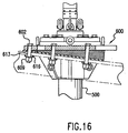
- Figs. 13-17 illustrate one configuration for securing an embodiment of the riser assembly of the present invention to a dynamic platform.
- Figs. 13 and 14 show side and top views, respectively, of the riser cable assembly 500 and platform assembly 600. Supporting structure of the platform is shown in phantom.
- split flange 606 is provided and securely mates within collar 510 of riser cable assembly 500.
- Split flange 606 rests on top of support flange 607 and is secured to platform assembly 600 by utilizing bolts 605.
- Platform assembly 600 is mounted at an angle with respect to the dynamic platform (shown in phantom). Platform assembly 600 is mounted at an angle in order to reduce the stresses applied to riser cable 200 as it extends downward toward the sea floor. An angle of 7 degrees is preferable.
- rear spacer 617 and side spacer 618 are provided. Rear and side spacers 617 and 618 are positioned between platform assembly 600 and the dynamic platform. Insulation plate 610 is positioned between rear spacer 617 and the dynamic platform. Platform assembly 600 is mounted to the dynamic platform by utilizing bolts 602, insulator sleeves 613, insulator spacers 616, and nuts 609.
- the platform assembly may be formed in several segments which, when assembled together, fit around riser cable assembly 500.
- the various segments may be assembled and joined together by utilizing studs 619 and nuts 608.
- Figs. 18-19 illustrate an alternative configuration for securing an embodiment of the riser assembly of the present invention to a dynamic platform.
- Figs. 18 and 19 show side and top views, respectively, of the riser cable assembly 500 and platform assembly 700. Again, supporting structure of the platform is shown in phantom.
- Fig. 20 which is a cross-sectional view of the embodiment of Figs. 18 and 19
- split flange 703 is provided and securely mates within collar 510 of riser cable assembly 500.
- Split flange 703 rests on top of support flange 704 and is secured to platform assembly 700 by utilizing bolts 702.
- platform assembly 700 is not mounted at an angle with respect to the dynamic platform in this embodiment.
- the platform assembly may be formed in several segments which, when assembled together, fit around riser cable assembly 500.
- the various segments may again be assembled and secured together by utilizing studs 708 and nuts 705.
- riser cable 200 was secured in lower cable connector assembly 400 by utilizing a dual cold flow arrangement and riser cable 200 and local cable 100 were secured in upper cable connector assembly 300 by utilizing a single cold flow arrangement for each cable, however, it is not required that this configuration of cold flow arrangements be utilized in each cable connector assembly.
- a single cold flow arrangement could be utilized in lower cable connector assembly 400 and dual cold flow arrangements could be utilized for connecting each of riser cable 200 and local cable 100 in upper cable connector assembly 300.
- Any number of cold flow arrangements could be utilized in each connector assembly depending upon the particular application in which the riser cable assembly is utilized.
- epoxy could be utilized in each of the upper and lower cable connector assemblies in order to enhance the connection between the connector assembly and the cable(s).
Landscapes
- Physics & Mathematics (AREA)
- General Physics & Mathematics (AREA)
- Optics & Photonics (AREA)
- Cable Accessories (AREA)
- Mechanical Coupling Of Light Guides (AREA)
- Light Guides In General And Applications Therefor (AREA)
Applications Claiming Priority (2)
| Application Number | Priority Date | Filing Date | Title |
|---|---|---|---|
| US15334898A | 1998-09-15 | 1998-09-15 | |
| US153348 | 1998-09-15 |
Publications (1)
| Publication Number | Publication Date |
|---|---|
| EP0987574A2 true EP0987574A2 (fr) | 2000-03-22 |
Family
ID=22546827
Family Applications (1)
| Application Number | Title | Priority Date | Filing Date |
|---|---|---|---|
| EP99117465A Withdrawn EP0987574A2 (fr) | 1998-09-15 | 1999-09-09 | Ensemble de câbles ascendants à fibres optiques |
Country Status (4)
| Country | Link |
|---|---|
| EP (1) | EP0987574A2 (fr) |
| JP (1) | JP2000155240A (fr) |
| AU (1) | AU4746899A (fr) |
| CA (1) | CA2281176A1 (fr) |
Cited By (1)
| Publication number | Priority date | Publication date | Assignee | Title |
|---|---|---|---|---|
| CN110761728A (zh) * | 2018-07-26 | 2020-02-07 | 中国石油天然气股份有限公司 | 防窜动结构及具有其的测井仪器 |
-
1999
- 1999-08-30 CA CA002281176A patent/CA2281176A1/fr not_active Abandoned
- 1999-09-09 AU AU47468/99A patent/AU4746899A/en not_active Abandoned
- 1999-09-09 EP EP99117465A patent/EP0987574A2/fr not_active Withdrawn
- 1999-09-16 JP JP11262186A patent/JP2000155240A/ja active Pending
Cited By (1)
| Publication number | Priority date | Publication date | Assignee | Title |
|---|---|---|---|---|
| CN110761728A (zh) * | 2018-07-26 | 2020-02-07 | 中国石油天然气股份有限公司 | 防窜动结构及具有其的测井仪器 |
Also Published As
| Publication number | Publication date |
|---|---|
| JP2000155240A (ja) | 2000-06-06 |
| CA2281176A1 (fr) | 2000-03-15 |
| AU4746899A (en) | 2000-03-23 |
Similar Documents
| Publication | Publication Date | Title |
|---|---|---|
| US7409127B1 (en) | Fiber optic assemblies suitable for adding nodes to a communication network | |
| EP0105597B1 (fr) | Système de connexion à fibre optique | |
| US4336977A (en) | Crimped connector assembly for fiber optic cables | |
| US9069151B2 (en) | Composite cable breakout assembly | |
| US4382653A (en) | Connector | |
| JP2868828B2 (ja) | 光ファイバケーブル接合装置 | |
| US20050170692A1 (en) | Compression connector with integral coupler | |
| US10852487B1 (en) | Hardened optical cable assemblies, optical plug connector assemblies, optical receptacle assemblies and optical connection systems having multiple optical fibers | |
| JPS63287916A (ja) | 複合ケ−ブルの端末部 | |
| US11906795B2 (en) | Fiber optic connector assembly with crimp tube subassembly and method of use | |
| JP2003531453A (ja) | 異なった寸法の同軸ケーブル用のコネクタ及び関連する方法 | |
| US5212750A (en) | Fiber optic harness having reduced weight and bulk, and method | |
| CN110212485A (zh) | 一种三芯高压海底电缆接头盒及其安装方法 | |
| US8920193B2 (en) | Preconnectorized coaxial cable connector apparatus | |
| JPH0440922B2 (fr) | ||
| US20060258208A1 (en) | High density mount for a co-axial connector | |
| US6227881B1 (en) | Cable management coupling and shielding interconnect system and method | |
| EP0497463A2 (fr) | Dispositif de blindage pour connecteurs | |
| EP0987574A2 (fr) | Ensemble de câbles ascendants à fibres optiques | |
| TW382663B (en) | Submarine fiber-optic cable joint with load-bearing casing | |
| US20260024966A1 (en) | Conductor terminations | |
| CN109560524B (zh) | 接头结构及具有其的连接装置 | |
| KR20070066981A (ko) | 편복선 동축 케이블용 압축 커넥터 | |
| US7431515B1 (en) | Fiber optic termini having multiple crimp portions and method of using same | |
| US20020170735A1 (en) | Electric cable joints and methods of making them |
Legal Events
| Date | Code | Title | Description |
|---|---|---|---|
| PUAI | Public reference made under article 153(3) epc to a published international application that has entered the european phase |
Free format text: ORIGINAL CODE: 0009012 |
|
| AK | Designated contracting states |
Kind code of ref document: A2 Designated state(s): AT BE CH CY DE DK ES FI FR GB GR IE IT LI LU MC NL PT SE |
|
| AX | Request for extension of the european patent |
Free format text: AL;LT;LV;MK;RO;SI |
|
| STAA | Information on the status of an ep patent application or granted ep patent |
Free format text: STATUS: THE APPLICATION HAS BEEN WITHDRAWN |
|
| 18W | Application withdrawn |
Withdrawal date: 20000414 |