EP0987736B1 - Keramische Lampe - Google Patents
Keramische Lampe Download PDFInfo
- Publication number
- EP0987736B1 EP0987736B1 EP99118467A EP99118467A EP0987736B1 EP 0987736 B1 EP0987736 B1 EP 0987736B1 EP 99118467 A EP99118467 A EP 99118467A EP 99118467 A EP99118467 A EP 99118467A EP 0987736 B1 EP0987736 B1 EP 0987736B1
- Authority
- EP
- European Patent Office
- Prior art keywords
- electrically conductive
- lamp
- hermetically
- sealing material
- conductive cermet
- Prior art date
- Legal status (The legal status is an assumption and is not a legal conclusion. Google has not performed a legal analysis and makes no representation as to the accuracy of the status listed.)
- Expired - Lifetime
Links
- 239000000919 ceramic Substances 0.000 title claims description 48
- 239000011195 cermet Substances 0.000 claims description 116
- 239000003566 sealing material Substances 0.000 claims description 90
- 238000007789 sealing Methods 0.000 claims description 84
- VYPSYNLAJGMNEJ-UHFFFAOYSA-N Silicium dioxide Chemical compound O=[Si]=O VYPSYNLAJGMNEJ-UHFFFAOYSA-N 0.000 claims description 21
- 239000000377 silicon dioxide Substances 0.000 claims description 15
- 239000000463 material Substances 0.000 claims description 13
- 239000000155 melt Substances 0.000 claims description 8
- 238000009792 diffusion process Methods 0.000 claims description 7
- 235000012239 silicon dioxide Nutrition 0.000 claims description 6
- 239000010410 layer Substances 0.000 description 35
- 238000002474 experimental method Methods 0.000 description 17
- 229910052736 halogen Inorganic materials 0.000 description 12
- 150000002367 halogens Chemical class 0.000 description 11
- 230000035882 stress Effects 0.000 description 10
- 229910052681 coesite Inorganic materials 0.000 description 9
- 229910052906 cristobalite Inorganic materials 0.000 description 9
- TWNQGVIAIRXVLR-UHFFFAOYSA-N oxo(oxoalumanyloxy)alumane Chemical compound O=[Al]O[Al]=O TWNQGVIAIRXVLR-UHFFFAOYSA-N 0.000 description 9
- 229910052682 stishovite Inorganic materials 0.000 description 9
- 239000002344 surface layer Substances 0.000 description 9
- 229910052905 tridymite Inorganic materials 0.000 description 9
- 230000015572 biosynthetic process Effects 0.000 description 8
- 229910017970 MgO-SiO2 Inorganic materials 0.000 description 7
- 238000003466 welding Methods 0.000 description 7
- 239000000126 substance Substances 0.000 description 6
- 238000005336 cracking Methods 0.000 description 5
- 238000011156 evaluation Methods 0.000 description 5
- 229910052751 metal Inorganic materials 0.000 description 5
- 239000002184 metal Substances 0.000 description 5
- 239000000203 mixture Substances 0.000 description 5
- PNEYBMLMFCGWSK-UHFFFAOYSA-N aluminium oxide Inorganic materials [O-2].[O-2].[O-2].[Al+3].[Al+3] PNEYBMLMFCGWSK-UHFFFAOYSA-N 0.000 description 4
- 238000010438 heat treatment Methods 0.000 description 4
- 238000000034 method Methods 0.000 description 4
- 230000005855 radiation Effects 0.000 description 4
- ZOKXTWBITQBERF-UHFFFAOYSA-N Molybdenum Chemical compound [Mo] ZOKXTWBITQBERF-UHFFFAOYSA-N 0.000 description 3
- 239000000470 constituent Substances 0.000 description 3
- NLQFUUYNQFMIJW-UHFFFAOYSA-N dysprosium(III) oxide Inorganic materials O=[Dy]O[Dy]=O NLQFUUYNQFMIJW-UHFFFAOYSA-N 0.000 description 3
- 229910052750 molybdenum Inorganic materials 0.000 description 3
- 239000011733 molybdenum Substances 0.000 description 3
- 229910052593 corundum Inorganic materials 0.000 description 2
- 239000007791 liquid phase Substances 0.000 description 2
- 230000002093 peripheral effect Effects 0.000 description 2
- 239000000843 powder Substances 0.000 description 2
- 238000003825 pressing Methods 0.000 description 2
- 238000005245 sintering Methods 0.000 description 2
- 239000007790 solid phase Substances 0.000 description 2
- WFKWXMTUELFFGS-UHFFFAOYSA-N tungsten Chemical compound [W] WFKWXMTUELFFGS-UHFFFAOYSA-N 0.000 description 2
- 229910052721 tungsten Inorganic materials 0.000 description 2
- 239000010937 tungsten Substances 0.000 description 2
- 229910001845 yogo sapphire Inorganic materials 0.000 description 2
- 238000002441 X-ray diffraction Methods 0.000 description 1
- 230000001070 adhesive effect Effects 0.000 description 1
- 230000002146 bilateral effect Effects 0.000 description 1
- 239000011248 coating agent Substances 0.000 description 1
- 238000000576 coating method Methods 0.000 description 1
- 239000002131 composite material Substances 0.000 description 1
- 230000007547 defect Effects 0.000 description 1
- FJBFPHVGVWTDIP-UHFFFAOYSA-N dibromomethane Chemical compound BrCBr FJBFPHVGVWTDIP-UHFFFAOYSA-N 0.000 description 1
- 238000009826 distribution Methods 0.000 description 1
- 238000010891 electric arc Methods 0.000 description 1
- 239000000945 filler Substances 0.000 description 1
- 239000010419 fine particle Substances 0.000 description 1
- 125000005843 halogen group Chemical group 0.000 description 1
- 238000004519 manufacturing process Methods 0.000 description 1
- 238000002844 melting Methods 0.000 description 1
- 230000008018 melting Effects 0.000 description 1
- 229910001507 metal halide Inorganic materials 0.000 description 1
- 150000005309 metal halides Chemical class 0.000 description 1
- 238000002156 mixing Methods 0.000 description 1
- 239000012768 molten material Substances 0.000 description 1
- SIWVEOZUMHYXCS-UHFFFAOYSA-N oxo(oxoyttriooxy)yttrium Chemical compound O=[Y]O[Y]=O SIWVEOZUMHYXCS-UHFFFAOYSA-N 0.000 description 1
- 239000003870 refractory metal Substances 0.000 description 1
- 238000004626 scanning electron microscopy Methods 0.000 description 1
- 230000008646 thermal stress Effects 0.000 description 1
- XLYOFNOQVPJJNP-UHFFFAOYSA-N water Substances O XLYOFNOQVPJJNP-UHFFFAOYSA-N 0.000 description 1
- 229910052724 xenon Inorganic materials 0.000 description 1
- FHNFHKCVQCLJFQ-UHFFFAOYSA-N xenon atom Chemical compound [Xe] FHNFHKCVQCLJFQ-UHFFFAOYSA-N 0.000 description 1
Images


Classifications
-
- H—ELECTRICITY
- H01—ELECTRIC ELEMENTS
- H01J—ELECTRIC DISCHARGE TUBES OR DISCHARGE LAMPS
- H01J61/00—Gas-discharge or vapour-discharge lamps
- H01J61/02—Details
- H01J61/36—Seals between parts of vessels; Seals for leading-in conductors; Leading-in conductors
- H01J61/361—Seals between parts of vessel
- H01J61/363—End-disc seals or plug seals
-
- H—ELECTRICITY
- H01—ELECTRIC ELEMENTS
- H01J—ELECTRIC DISCHARGE TUBES OR DISCHARGE LAMPS
- H01J61/00—Gas-discharge or vapour-discharge lamps
- H01J61/02—Details
- H01J61/36—Seals between parts of vessels; Seals for leading-in conductors; Leading-in conductors
- H01J61/366—Seals for leading-in conductors
Definitions
- the invention relates to a ceramic lamp having a lamp vessel made of translucent ceramic and using a hermetically sealing body of electrically conductive cermet to route current into the lamp vessel, the sealing body being hermetically sealed relative to sealing portions of the lamp vessel via a sealing material.
- a ceramic lamp in which the lamp vessel is made of a translucent ceramic and an electrically conductive cermet is used for the hermetically sealing body, and thus current is routed into the lamp vessel, and in which the lamp vessel is hermetically sealed relative to the sealing body using a sealing material, conventionally several sealing processes are performed.
- Fig. 11 shows, for example, an arrangement in which a hermetically sealing tube portion 3 is connected on opposite ends of a bulb portion 2, and the periphery of hermetically sealing bodies 4 of electrically conductive cermet is sealed relative to the inside wall of the tube portions 3 of the lamp vessel 1 using a sealing material 5, and thus, hermetically sealed portions 7 are formed.
- a hermetically sealing tube portion 3 is connected on opposite ends of a bulb portion 2, and the periphery of hermetically sealing bodies 4 of electrically conductive cermet is sealed relative to the inside wall of the tube portions 3 of the lamp vessel 1 using a sealing material 5, and thus, hermetically sealed portions 7 are formed.
- a hermetically sealing tube portion 3 is connected on opposite ends of a bulb portion 2
- the periphery of hermetically sealing bodies 4 of electrically conductive cermet is sealed relative to the inside wall of the tube portions 3 of the lamp vessel 1 using a sealing material 5, and thus, hermetically sealed portions 7 are formed.
- One such lamp is described,
- a process is known in which, in one of the hermetically sealed ends of a lamp with bilateral hermetic seals (of the double-end type), a hermetically sealing body of electrically conductive cermet and a hermetically sealed tube portion of the lamp vessel are sintered to one another in one part, and in which the other hermetically sealed end, upon evacuation of the lamp, is sealed with a sealing material.
- hermetically sealing bodies of electrically conductive cermet are enclosed with a sealing material in a hermetically sealed tube, there are differences in the coefficients of linear expansion between the respective components of the hermetically sealed portions, i.e., between the hermetically sealed tube, the hermetically sealing body, the sealing material and the electrically conductive supply component, such as the upholding part of the electrode and the like. Therefore, there are cases in which cracks form in these hermetically sealing portions, or as a result of these cracks, leaks occur. In the hermetically sealed portions of a conventional ceramic lamp in which the electrically conductive cermet which is conventionally present is used as the hermetically sealing body, to date sufficiently reliability could not be achieved.
- US 4602956 A discloses sealing bodies for a metal halide light arc discharge lamp, wherein said sealing bodies of a composite cermet have a central core containing refractory metal in an amount to make it sufficiently electrically conductive to provide operating current to an arc tube electrode, and have at least one outer layer containing alumina in an amount to provide a thermal expansion coefficient which is compatible with that of the arc tube wall made of polycristalline alumina.
- Finer gradations can be achieved by increasing the number of layers surrounding the core, and progressively increasing one or more constituents at the expense of the remaining constituents, from layer to layer. Where the gradations are sufficiently fine and sintering is carried out for a time sufficient to produce substantial diffusion of constituents between layers, it is possible to achieve a continuous gradation of composition and properties from center to outer wall.
- a primary object of the present invention is to provide a ceramic lamp in which the hermetically sealing bodies of electrically conductive cermet in the hermetically sealed tube portion of the lamp vessel are sealed with a sealing material in a manner which reduces the difference of the coefficients of linear expansion between the components of the lamp, and at the same time, and to otherwise insure that the arrangement and material components of the hermetically sealed portions have a high reliability and are tight.
- a discharge lamp of translucent ceramic which has a lamp vessel which has a bulb portion and a hermetically sealed tube portion which is connected to the bulb portion, in which furthermore, in the bulb portion, there are electrically conductive supply components, and in which, by seal welding of the hermetically sealing bodies of electrically conductive cermet on the hermetically sealed tube portion with a sealing material, a hermetically sealed arrangement is obtained, the base parts of the above described electrically conductive supply components being inserted into the hermetically sealed bodies of electrically conductive cermet, the indicated object of the invention is obtained by an intermediate layer being formed in the area of the surface layers of the respective hermetically sealing body, the intermediate layer having components of the electrically conductive cermet of the hermetically sealing body intermixed with components of the sealing materials.
- electrically conductive supply component in a discharge lamp is defined as electrodes and the upholding parts of the electrode, and in an incandescent lamp, such as a halogen lamp or the like, filaments and inner lead pins.
- the object is also achieved in accordance with the invention, in a ceramic lamp, by providing the electrically conductive cermet with components which melt at a temperature at which the sealing material melts and welding the hermetically sealing body to the hermetically sealed tube portion.
- the object is achieved according to the invention in a ceramic lamp by having the noted intermediate layer have an area with a relatively small concentration gradient which is formed by a diffusion of the components of the sealing material into the intermediate layer and an area with a steep concentration gradient thereof.
- the object is advantageously achieved in accordance with the invention by the intermediate layer being an area with a thickness of at least 20 ⁇ m (microns) in which the concentration of the components of the sealing material is at least half the concentration in the pure sealing material.
- the expression "area of the intermediate layer with a thickness " is defined mainly as the area in which the surface layers of the electrically conductive cermet are caused to melt, and in this way, components of the sealing material in a larger amount are able to diffuse into the molten material.
- This thickness furthermore, represents the distance from a position at the outer surface of the cermet before seal welding to the inside as far as the position where the concentration of the components, which are distributed in the intermediate layer and which are contained in the sealing material, however are not contained in the electrically conductive cermet, reaches 1/2 of the initial concentration of these components in the sealing material.
- the object is advantageously achieved in accordance with the invention especially in that the sealing material and the electrically conductive cermet contain the same component, specifically silicon dioxide.
- the object is advantageously achieved according to the invention, in a ceramic lamp, by the sealing material filling at least a gap between inside faces of the hermetically sealing body and bordering outside faces of the hermetically sealed tube of the lamp vessel.
- the object is also advantageously achieved in accordance with the invention, in a ceramic lamp, in that the surface of the electrically conductive cermet which faces outward of the lamp is at least partially covered with the sealing material.
- the object is advantageously achieved according to the invention, in a ceramic lamp, by the following conditions being met at the same time:
- ⁇ 1 , ⁇ 2 , and ⁇ 3 are, respectively, the average coefficients of linear expansion of the ceramic of the lamp vessel, the electrically conductive cermet of the hermetically sealing body and the sealing materials at 25°C to 350°C.
- the object is advantageously achieved in accordance with the invention by holes of the hermetically sealing body of electrically conductive cermet into which the base parts of the electrically conductive supply components are inserted each having a widened entry opening.
- the object is also advantageously achieved according to the invention, in a ceramic lamp, by the condition
- the object is advantageously achieved in accordance with the invention, in a ceramic lamp, by the faces of the hermetically sealing body of electrically conductive cermet and the ends of the hermetically sealed tube of the lamp vessel being attached to one another with sealing material and sealed relative to one another, and by the difference between the outside diameter of the ends of the hermetically sealing body of electrically conductive cermet and the outside diameter of the ends of the hermetically sealed tube of the lamp vessel being less than or equal to 0.7 mm.
- the object is advantageously achieved according to the invention, in a ceramic lamp, by the lamp being used in such a way that, in the operating state of the lamp, the temperature of the hermetically sealing body of electrically conductive cermet is kept constant at 760°C or less.
- the electrically conductive cermet contains components which melt at the operating temperature at which the sealing material melts and the hermetically sealing bodies in the hermetically sealed tube portion are sealed, the formation of an intermediate layer is promoted.
- the above described intermediate layer has an area with a relatively small concentration gradient in which components of the sealing material are distributed and an area with a steep concentration gradient thereof, the stress on the connection boundary between the sealing material and the electrically conductive cermet is reduced.
- the concentration gradient As the distance from the applied sealing material increases, the concentration of the components of the sealing material which have diffused in becomes clearly less, the concentration gradient correspondingly greater.
- this intermediate area has an area with a thickness of at least 20 ⁇ m (microns) when an area is reached in which the concentration of the components which have diffused in is cut in half, the reduction of the stress which occurs on the connection boundary is improved even more.
- the sealing material and the electrically conductive cermet contain the same component, specifically silicon dioxide, the temperature can be reduced at which the area of the surface layers of the cermet begins to melt. In this way, the formation of the intermediate layer is simplified even more.
- sealing material extends as far as the face of the hermetically sealed tube portion of the lamp vessel, strong, highly hermetic sealing is produced.
- the electrically conductive cermet which face toward the lamp exterior is at least partially covered with the sealing material, the concentration of water absorbed on the outside surface of the electrically conductive cermet is reduced.
- the electrically conductive cermet of the hermetically sealing body and the sealing material is reduced to ⁇ 1 x 10 -6 /K, the formation of macroscopic stress between the electrically conductive cermet and the lamp vessel is reduced.
- the opening diameter of the holes of the hermetically sealing body of electrically conductive cermet into which the base parts of the electrically conductive supply components are inserted is made larger than the inside diameter of the holes, the amount of coating of sealing material in the openings of the holes can be increased. Thus the stress in the vicinity of the openings is reduced.
- the sealing material is smoothly joined to the outside peripheral area of the hermetically sealed tube because only small stages between the two parts are present.
- the temperature of the hermetically sealing body of electrically conductive cermet is kept constant at less than or equal to 760°C, the thermal stress which forms between the respective substances within the electrically conductive cermet can be kept low.
- Fig. 1 is a schematic cross section of one embodiment of a ceramic discharge lamp in accordance with the invention.
- the lamp is a 20 W metal halogen lamp.
- the outside diameter of the bulb portion 2 is 5.8 mm, the total length of the lamp is 24 mm, and the outside diameter of the hermetically sealed tube part 3 is 1.8 mm.
- the lamp vessel 1 contains 4 mg DyI 3 -TlI-NaI, 2.6 mg of Hg and 13 kPa Ar as the filler gas.
- the hermetically sealing body 4 of electrically conductive cermet is columnar with an outside diameter of 1.8 mm and a length of 3.0 mm.
- the end face of the hermetically sealed tube part 3 and the end face of the hermetically sealing body 4 are sealed via sealing material 5 creating a hermetically sealed portion 7.
- the lamp vessel 1 is made of translucent ceramic which is a sintered body of polycrystalline aluminum oxide.
- the bulb portion 2 of lamp vessel 1 is connected to the hermetically sealed tube portion 3, in this embodiment, by being integrally sintered to one another.
- the bulb portion 2 and the hermetically sealed tube part 3 are temporarily sintered separately, then combined with one another, then completely sintered and formed.
- a polycrystalline YAG sintered body or a polycrystalline yttrium oxide sintered body, or the like is used for the lamp vessel 1.
- each electrode 8 there is a pair of electrodes 8 opposite one another.
- the tip of the upholding part 6 of the electrode is wound with a metal coil and is arranged together with the upholding part 6 of the electrode as an electrically conductive supply component.
- the base part 61 of each upholding part 6 of the electrode is inserted into a hermetically sealing body 4 of electrically conductive cermet. Tungsten or molybdenum is used for the electrodes 8 and the upholding part 6 of the electrode.
- the electrically conductive cermet which is used as the hermetically sealing body 4
- a mixture of Mo-Al 2 O 3 -MgO-SiO 2 (40:35:15:10 % volumetric proportion) is used.
- the composition of the cermet is, however, not limited thereto, but can be changed with consideration of the coefficient of linear expansion of the material of the lamp vessel 1 to be used, for example, a suitable choice of 5 to 30% of silicon dioxide content being made.
- the above described electrically conductive cermet based on Mo-Al 2 O 3 -MgO-SiO 2 is produced by pressing the raw powder of fine particles of 5 ⁇ m (microns) or less of the respective material component, yielding a compacted body. This compacted body was heated at 1700°C for 5 minutes and sintered.
- the ends of the hermetically sealed tube and the hermetically sealing body 4 of electrically conductive cermet are sealed to one another by welding using a sealing material 5, by which a hermetically sealed arrangement is formed on both ends in this embodiment.
- the sealing material 5 extends to the outer surface of the sealed tube portion 3 of the lamp vessel 1, a mixture of Dy 2 O 3 -Al 2 O 3 -SiO 2 being used as the sealing material.
- a light irradiation heating device which is also called a "photo image furnace" and in which visible radiation and IR light are emitted from a radiation source and are focused by a reflector at a focal point, so that a substance which has been placed at the focal point is briefly heated by increasing the temperature.
- the radiation source of the visible rays and IR light is a halogen lamp, a xenon lamp or the like. Furthermore, it is possible to use an IR laser as the radiation source.
- Fig. 3 is a schematic of the arrangement of a light irradiation heating device which was used to form this embodiment.
- two halogen lamps 11 with a power of 1 kW were used.
- the visible rays and the IR rays emitted by the halogen lamps 11 were focused by means of a reflector 12 on the hermetically sealed portions 7 of the lamp vessel 1 which was located in a translucent vacuum vessel 13.
- the sealing material was briefly heated, i.e., for only a few seconds, thus melted, and afterwards, it was held at the temperature at which the molten sealing material is brought into a solid phase for a certain time, i.e., roughly 20 seconds, by which sealing has taken place.
- the light irradiation heating raises the temperature of the sealing material, which conventionally melts at roughly 1600° C, for an instant to roughly 1800°C, at which the operating temperature for sealing the hermetically sealed portions lies. At this operating temperature, the material components of the electrically conductive cermet partially melt.
- an intermediate layer 20 is formed in the area of the surface layers of the hermetically sealing body 4 in which the components of sealing material 5 and the material components of the electrically conductive cermet are mixed with one another. This state is shown schematically in Fig. 4.
- both the electrically conductive cermet and also the sealing material contain the same component, silicon dioxide, which melts at the operating temperature for sealing, i.e., at roughly 1800°C, the material components of the electrically conductive cermet of the hermetically sealing body 4 in the area of the surface layers of the body 4 melt when the sealing material melts.
- Fig. 5 shows another embodiment of the type of lamp according to the invention in which a sleeve 9 of ceramic is held in a concave area with which the inside face of the hermetically sealing body 4 of electrically conductive cermet is provided.
- the components of the electrically conductive cermet melt, forming a liquid phase. Since, in general, the diffusion rate of the molecules in the liquid phase is far greater than the diffusion rate of the solid phase, during the short time of photoheating, a layer is formed in which the components of the sealing material and the components of the electrically conductive cermet are distributed and mixed with one another. It is assumed that, by forming this layer, the stress is distributed which forms at the boundary between the sealing material and the electrically conductive cermet. In this invention, the layer formed by this mixing is called the "intermediate layer 20".
- the concentration gradient formed by the diffusion thereof is shown by way of example in Fig. 6, which can be confirmed by SEM-EDS (scanning electron microscopy and x-ray analysis). Furthermore, an area with a thickness of at least 20 ⁇ m (microns) in the intermediate layer of the finished hermetically sealed portion can also be ascertained within which the concentration has not yet been reduced by diffusion to less than half the concentration in the sealing material used. Only at a distance of greater than 20 ⁇ m (microns) from the surface of the metal ceramic is the concentration of the components of the sealing material in the intermediate layer less than half the concentration of the pure sealing material. This thickness can be measured by SEM-EDS.
- the electrically conductive cermet contains silicon dioxide and is heated to 1800°C, i.e., to a relatively low temperature, an area is easily obtained in which the thickness is greater than or equal to 20 ⁇ m (microns) when the concentration of the scattered components of the sealing material of the intermediate layer has retreated to half
- the sealing material such that the sealing material melts and the surface of the electrically conductive cermet is covered therewith, and by photoheating and seal welding being performed, the lateral outside surface of the electrically conductive cermet which is adjacent to the end of the tube portion is covered with the sealing material in the finished hermetically sealed portions.
- the material is chosen such that the following conditions are met at the same time:
- ⁇ 1 , ⁇ 2 , and ⁇ 3 are, respectively, the average coefficients of linear expansion of the ceramic of the lamp vessel, the electrically conductive cermet of the hermetically sealing body and the sealing material at 25°C to 350°C.
- the average coefficients of linear expansion of the sintered body of the polycrystalline aluminum oxide as the ceramic of the lamp vessel are 6.8 x 10 -6 /K
- of the cermet based on Mo-Al 2 O 3 -MgO-SiO 2 as the electrically conductive cermet are 6.5 x 10 -6 /K at 25 to 350°C
- of the sealing material based on Dy 2 O 3 -Al 2 O 3 -SiO 2 at 25 to 350°C are 6.6 x 10 -6 /K.
- the stress exerted on the sealing material which often causes cracks, can be reduced by this choice of the ceramic of the lamp vessel, the electrically conductive cermet of the hermetically sealing body, and the sealing material with similar coefficients of linear expansion.
- a lamp was produced using an electrically conductive cermet of Al 2 O 3 -Mo.
- the average coefficient of linear expansion of this cermet at 25 to 350°C is 5 x 10 -6 /K.
- the difference between the coefficients of linear expansion of the translucent sintered body of polycrystalline aluminum oxide of the lamp vessel and of the sealing material based on Dy 2 O 3 -Al 2 O 3 -SiO 2 and this electrically conductive cermet is greater than 1 x 10 -6 /K.
- the diameter of the base part of the upholding part 6 of the electrode in the vicinity of its tip is progressively reduced in order to increase the reliability of the hermetically sealed portion. This measure reduces the stress in the vicinity of the base part of the upholding part 6 of the electrode in the electrically conductive cermet.
- a lamp was produced using the hermetically sealing body 4 of electrically conductive cermet with holes 21 which each have a widened opening in which the base parts of the upholding part 6 of the electrode are inserted.
- the bottom surface 22 of the hole 21 of the hermetically sealing body of electrically conductive cermet in which the base part of the upholding part of the electrode is inserted was made in the form of a polyhedral, convex surface as is illustrated in Fig. 9. This was done by a pin with a polyhedral tip shape being placed in the press mold to keep the hole 21 open when pressing the raw powder before sintering of the cermet. Also the shape of the base part of the upholding part of the electrode corresponding to the hole was matched to the polyhedral convex surface of the bottom. This measure can prevent formation of cracks locally.
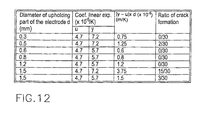
- the material was chosen such that the condition
- d (mm) is the diameter of the upholding parts 6 of the electrode 8 which are inserted into the hermetically sealing bodies of electrically conductive cermet
- y and u (1/K) are the average coefficients of linear expansion of the electrically conductive cermet and of the upholding part of the electrode at 25 to 350°C, respectively.
- d is 0.3 mm
- for y is 6.5 x 10 -6 /K
- u is 4.7 x 10 -6 /K. This reduces the formation of macroscopic stress between the upholding part of the electrode and the electrically conductive cermet.
- Fig. 12 shows the results of an experiment in which the upholding parts of the electrode were inserted into the electrically conductive cermet, the entirety was sintered and the presence or absence of cracks was checked to select the above described numerical values. The cracks were observed at the locations at which the inserted upholding parts of the electrodes project out of the electrically conductive cermet.
- the ends of the hermetically sealing body of electrically conductive cermet and the end of the hermetically sealed tube of the lamp vessel were sealed relative one another. Both the outside diameter of the ends of the hermetically sealing body of electrically conductive cermet and also the outside diameter of the end of the hermetically sealed tube of the lamp vessel are 1.8 mm.
- the sealing material extended as far as the face of the hermetically sealed tube of the lamp vessel.
- the failure rate is thus as good as 0 in that, in the operating state of the lamp, the temperature of the hermetically sealing body of the electrically conductive cermet is kept constant at less than or equal 760°C.
- Fig. 10 shows a 4 kW ceramic halogen lamp 31 in which the outside diameter of the bulb portion 40 is 10 mm and the total length is 520 mm.
- Ar + CH 2 Br 2 (0.1% by volume) with a pressure of 70 kPa were added.
- the faces of the hermetically sealed tube portions 41 and the faces of the hermetically sealing bodies 32 are sealed relative to one another via the sealing material 33.
- the lamp vessel 31 is made of a translucent sintered body of a polycrystalline aluminum oxide. Furthermore, the hermetically sealing body 32 is made of an electrically conductive cermet based on Mo-Al 2 O 3 -MgO-SiO 2 (40:35:15:10% volumetric proportion). The sealing material 33 used is based on Dy 2 O 3 -Al 2 O 3 -SiO 2 . Also shown in Fig. 10 are an inner lead pin 34, a filament 35, and an outer lead pin 36.
- hermetically sealed portions 37 were seal welded by means of the sealing material.
- intermediate layers 20 were formed in the area of the surface layers of the hermetically sealing body 32 of electrically conductive cermet.
- the intermediate layer 20 had a thickness of roughly 50 ⁇ m (microns) in its thicker area.
- the temperature of the hermetically sealed portions in operation were at most 650°C.
- the lamp output was controlled such that the temperature of the hermetically sealed portions was 800° C.
- the lamp was operated for 15 minutes and turned off for 15 minutes; this was considered one cycle.
- the experiment was completed after 3000 cycles.
- the experiment is stopped.
- the leakage is determined by the materials added to the inner tube being deposited on the inside of the outer tube of the double tube.
- a lamp was produced under the same conditions as in the above described experiment 3, except for the condition of the electrically conductive cermet, and the temperature cycle experiment was performed.
- the sealing material melts in the area of the surface layers of the electrically conductive cermet of the respective hermetically sealing body, an intermediate layer is formed, by which the difference between the coefficient of linear expansion of the lamp components is reduced. Furthermore, the sealing material was joined to the electrically conductive cermet with an extremely good adhesive property. The reliability of the hermetically sealed portions of the lamp was thus greatly increased compared to a conventional lamp in which the electrically conductive cermet was sealed by a sealing material.
Landscapes
- Vessels And Coating Films For Discharge Lamps (AREA)
Claims (12)
- Keramische Lampe aus lichtdurchlässiger Keramik, aufweisend ein Lampengefäß (1) mit einem Kolbenbereich (2) und mit hermetisch abgedichteten Röhrenbereichen (3), die mit dem Kolbenbereich (2) verbunden sind, elektrisch leitende Versorgungsbauteile im Kolbenbereich (2) und hermetisch abdichtende Körper (4) aus elektrisch leitender Metallkeramik, die mit einem Dichtungsmaterial (5) an die hermetisch abgedichteten Röhrenbereiche (3) angeschweißt sind, um eine hermetisch abgedichtete Anordnung zu bilden, wobei Basisteile (61) der elektrisch leitenden Versorgungsbauteile in den hermetisch abgedichteten Körpern (4) aus elektrisch leitender Metallkeramik gehalten werden,
dadurch gekennzeichnet, dass in einem Oberflächenbereich des hermetisch abdichtenden Körpers (4) eine Zwischenschicht (20) gebildet ist, wobei in der Zwischenschicht (20) Komponenten der elektrisch leitenden Metallkeramik des hermetisch abdichtenden Körpers (4) mit Komponenten des Dichtungsmaterials (5) vermischt sind. - Keramische Lampe nach Anspruch 1, worin die elektrisch leitende Metallkeramik Komponenten enthält, welche bei einer Temperatur schmelzen, bei welcher das Dichtungsmaterial (5) schmilzt und bei welcher die hermetisch abdichtenden Körper (4) mit den hermetisch abgedichteten Röhrenbereichen (3) verschweißt werden.
- Keramische Lampe nach Anspruch 1 oder 2, worin die Zwischenschicht (20) einen Bereich mit einem relativ kleinen Konzentrationsgradienten, welcher durch eine Diffusion von Komponenten des Dichtungsmaterials (5) in die Zwischenschicht (20) entsteht, und einen Bereich mit einem steilen Konzentrationsgradienten von Komponenten des Dichtungsmaterials (5) umfasst.
- Keramische Lampe nach einem der Ansprüche 1 bis 3, worin die Zwischenschicht (20) ein Bereich mit einer Dicke von größer oder gleich 20 µm (microns) ist und in welcher die Konzentration der Komponenten des Dichtungsmaterials (5) wenigstens die Hälfte der Konzentration der Komponenten in dem reinen Dichtungsmaterial (5) ist.
- Keramische Lampe nach einem der Ansprüche 1 bis 4, worin das Dichtungsmaterial (5) und die elektrisch leitende Metallkeramik Siliciumdioxid als gemeinsame Komponente enthalten.
- Keramische Lampe nach einem der Ansprüche 1 bis 5, worin Innenstirnseiten des hermetisch abdichtenden Körpers (4) an Außenstirnseiten der hermetisch abgedichteten Röhre des Lampengefäßes (1) angrenzen und worin das Dichtungsmaterial (5) zumindest einen Spalt zwischen den Stirnseiten füllt.
- Keramische Lampe nach einem der Ansprüche 1 bis 6, worin eine nach außen weisende Oberfläche der elektrisch leitenden Metallkeramik zumindest teilweise mit dem Dichtungsmaterial (5) bedeckt ist.
- Keramische Lampe nach einem der Ansprüche 1 bis 7, worin die folgenden Bedingungen gleichzeitig erfüllt sind:
- Keramische Lampe nach einem der Ansprüche 1 bis 8, worin jeder der hermetisch abdichtenden Körper (4) aus elektrisch leitender Metallkeramik eine Öffnung (21) aufweist, in welche jeweils eines der Basisteile (61) der elektrisch leitenden Versorgungsbauteile eingesetzt ist, wobei die Öffnung (21) eine erweiterte Eingangsöffnung aufweist.
- Keramische Lampe nach einem der Ansprüche 1 bis 9, worin die Bedingung |y - u| x d ≤ 1,2 x 10⁻⁹ (m/K) erfüllt ist, wobei d (m) der Durchmesser der elektrisch leitenden Versorgungsbauteile ist, welche in die hermetisch abdichtenden Körper (4) aus elektrisch leitender Metallkeramik eingesetzt sind, und y und u (1/K) die durchschnittlichen linearen Ausdehnungskoeffizienten der elektrisch leitenden Metallkeramik bzw. des Materials für das elektrisch leitende Versorgungsbauteil bei 25 bis 350 °C sind.
- Keramische Lampe nach einem der Ansprüche 1 bis 10, worin die Enden der hermetisch abdichtenden Körper (4) aus elektrisch leitender Metallkeramik und die Enden der hermetisch abgedichteten Röhre des Lampengefäßes (1) aneinander befestigt und mit dem Dichtungsmaterial (5) gegeneinander abgedichtet sind und ein Unterschied zwischen einem Außendurchmesser der Enden des hermetisch abdichtenden Körpers (4) aus elektrisch leitender Metallkeramik und einem Außendurchmesser der Enden der hermetisch abgedichteten Röhre des Lampengefäßes (1) 0,7 mm oder kleiner ist.
- Verwendung einer keramischen Lampe nach einem der Ansprüche 1 bis 11 unter solchen Bedingungen, dass die hermetisch abdichtenden Körper (4) aus elektrisch leitender Metallkeramik bei einer im Wesentlichen konstanten Temperatur von höchstens 760 °C gehalten werden.
Applications Claiming Priority (2)
| Application Number | Priority Date | Filing Date | Title |
|---|---|---|---|
| JP28205598 | 1998-09-18 | ||
| JP28205598A JP3397145B2 (ja) | 1998-09-18 | 1998-09-18 | セラミック製ランプ |
Publications (2)
| Publication Number | Publication Date |
|---|---|
| EP0987736A1 EP0987736A1 (de) | 2000-03-22 |
| EP0987736B1 true EP0987736B1 (de) | 2005-03-02 |
Family
ID=17647580
Family Applications (1)
| Application Number | Title | Priority Date | Filing Date |
|---|---|---|---|
| EP99118467A Expired - Lifetime EP0987736B1 (de) | 1998-09-18 | 1999-09-17 | Keramische Lampe |
Country Status (4)
| Country | Link |
|---|---|
| US (1) | US6313582B1 (de) |
| EP (1) | EP0987736B1 (de) |
| JP (1) | JP3397145B2 (de) |
| DE (1) | DE69923902T2 (de) |
Cited By (1)
| Publication number | Priority date | Publication date | Assignee | Title |
|---|---|---|---|---|
| DE102006052761A1 (de) * | 2006-11-08 | 2008-05-15 | Patent-Treuhand-Gesellschaft für elektrische Glühlampen mbH | Keramisches Entladungsgefäß und Hochdruckentladungslampe mit einem derartigen Entladungsgefäß |
Families Citing this family (16)
| Publication number | Priority date | Publication date | Assignee | Title |
|---|---|---|---|---|
| EP1043754B1 (de) * | 1999-04-06 | 2004-05-26 | Ushiodenki Kabushiki Kaisha | Lampenabdichtung mit einem abhängigen Gradienten |
| DE60016557T2 (de) * | 1999-08-31 | 2005-12-15 | Koninklijke Philips Electronics N.V. | Metallhalogenidlampe |
| WO2001082331A1 (en) * | 2000-04-19 | 2001-11-01 | Koninklijke Philips Electronics N.V. | High-pressure discharge lamp |
| EP1182681B1 (de) * | 2000-08-23 | 2006-03-01 | General Electric Company | Spritzgegossene Keramik-Metallhalogenidbogenröhre mit einem nicht-konischen Ende |
| JP3591439B2 (ja) * | 2000-09-21 | 2004-11-17 | ウシオ電機株式会社 | ショートアーク放電ランプ |
| US7035932B1 (en) * | 2000-10-27 | 2006-04-25 | Eric Morgan Dowling | Federated multiprotocol communication |
| EP1205963B1 (de) * | 2000-11-07 | 2012-01-18 | Panasonic Corporation | Hochdruckentladungslampe und Bogenröhre |
| JP3960796B2 (ja) * | 2001-12-27 | 2007-08-15 | 日本碍子株式会社 | 接合体、高圧放電灯用組み立て体および高圧放電灯 |
| US6791250B2 (en) * | 2002-10-23 | 2004-09-14 | Eye Lighting International | Seal and flag assembly for lamp base sidewire welding |
| US7132797B2 (en) * | 2002-12-18 | 2006-11-07 | General Electric Company | Hermetical end-to-end sealing techniques and lamp having uniquely sealed components |
| US6774547B1 (en) | 2003-06-26 | 2004-08-10 | Osram Sylvania Inc. | Discharge lamp having a fluted electrical feed-through |
| JP4585823B2 (ja) * | 2004-09-24 | 2010-11-24 | 東芝ライテック株式会社 | 管球および封止部材 |
| DE102005003892A1 (de) * | 2005-01-27 | 2006-08-03 | Patent-Treuhand-Gesellschaft für elektrische Glühlampen mbH | Verfahren zum Testen einer Abdichtung |
| JP5281151B2 (ja) | 2008-05-05 | 2013-09-04 | ジャンス・ハオマイ・ライティング・サイエンス・アンド・テクノロジー・カンパニー・リミテッド | 複合hid電気アーク管 |
| WO2010151881A1 (en) * | 2009-06-26 | 2010-12-29 | Advanced Lighting Technologies, Inc. | Infrared halogen lamp with improved efficiency |
| EP3015845A1 (de) * | 2014-11-03 | 2016-05-04 | Anton Paar TriTec SA | Einrichtung zum Beheizen einer Materialprüfungsvorrichtung |
Family Cites Families (10)
| Publication number | Priority date | Publication date | Assignee | Title |
|---|---|---|---|---|
| NL185482C (nl) * | 1980-09-05 | 1991-01-16 | Philips Nv | Hogedrukontladingslamp. |
| NL8200783A (nl) * | 1982-02-26 | 1983-09-16 | Philips Nv | Hogedrukontladingslamp. |
| JPS6063871A (ja) * | 1983-09-19 | 1985-04-12 | Toshiba Corp | メタルハライドランプ |
| US4602956A (en) * | 1984-12-17 | 1986-07-29 | North American Philips Lighting Corporation | Cermet composites, process for producing them and arc tube incorporating them |
| GB8521809D0 (en) * | 1985-09-03 | 1985-10-09 | Emi Plc Thorn | Metal halide discharge lamps |
| US5404078A (en) * | 1991-08-20 | 1995-04-04 | Patent-Treuhand-Gesellschaft Fur Elektrische Gluhlampen Mbh | High-pressure discharge lamp and method of manufacture |
| JPH05334995A (ja) * | 1992-05-29 | 1993-12-17 | Iwasaki Electric Co Ltd | 金属蒸気放電灯 |
| DE4338377A1 (de) * | 1993-11-10 | 1995-05-11 | Patent Treuhand Ges Fuer Elektrische Gluehlampen Mbh | Metallhalogenidentladungslampe mit keramischem Entladungsgefäß und Herstellverfahren für eine derartige Lampe |
| EP0751549B1 (de) * | 1995-01-13 | 2003-08-06 | Ngk Insulators, Ltd. | Hochdruckentladungslampe und ihr herstellungsverfahren |
| JP3314123B2 (ja) * | 1995-03-23 | 2002-08-12 | 京セラ株式会社 | 金属蒸気放電灯用発光管 |
-
1998
- 1998-09-18 JP JP28205598A patent/JP3397145B2/ja not_active Expired - Fee Related
-
1999
- 1999-09-17 EP EP99118467A patent/EP0987736B1/de not_active Expired - Lifetime
- 1999-09-17 DE DE69923902T patent/DE69923902T2/de not_active Expired - Lifetime
- 1999-09-17 US US09/398,035 patent/US6313582B1/en not_active Expired - Fee Related
Cited By (1)
| Publication number | Priority date | Publication date | Assignee | Title |
|---|---|---|---|---|
| DE102006052761A1 (de) * | 2006-11-08 | 2008-05-15 | Patent-Treuhand-Gesellschaft für elektrische Glühlampen mbH | Keramisches Entladungsgefäß und Hochdruckentladungslampe mit einem derartigen Entladungsgefäß |
Also Published As
| Publication number | Publication date |
|---|---|
| DE69923902T2 (de) | 2006-04-06 |
| US6313582B1 (en) | 2001-11-06 |
| EP0987736A1 (de) | 2000-03-22 |
| JP2000100387A (ja) | 2000-04-07 |
| JP3397145B2 (ja) | 2003-04-14 |
| DE69923902D1 (de) | 2005-04-07 |
Similar Documents
| Publication | Publication Date | Title |
|---|---|---|
| EP0987736B1 (de) | Keramische Lampe | |
| KR100538392B1 (ko) | 세라믹밀봉장치,이러한밀봉장치를구비한램프,및이러한장치의제조방법 | |
| US5552670A (en) | Method of making a vacuum-tight seal between a ceramic and a metal part, sealed structure, and discharge lamp having the seal | |
| US5810635A (en) | High-pressure discharge lamp, method of its manufacture, and sealing material used with the method and the resulting lamp | |
| US6791266B2 (en) | Ceramic discharge chamber for a discharge lamp | |
| HU218226B (hu) | Záróelem nagynyomású kisülőlámpákhoz és eljárás a záróelem előállítására | |
| EP1568066B1 (de) | Hockdruckgasentladungslampe und verfahren zur herstellung | |
| JPH1167155A (ja) | 高圧放電ランプ | |
| US5159239A (en) | Electric lamp with SiO2 vessel and seal therefor | |
| JP2003297289A (ja) | 高圧放電ランプおよび多重管形高圧放電ランプならびに照明装置 | |
| EP1001453B1 (de) | Stromzuführungskörper für birne und verfahren zu seiner herstellung | |
| KR20030019167A (ko) | 고압방전 램프 및 그 제조방법 | |
| US20060279218A1 (en) | High-pressure discharge lamp, high-pressure discharge lamp operating apparatus, and illuminating apparatus | |
| JP2598983Y2 (ja) | 高圧放電ランプ | |
| CA2298270A1 (en) | Metal halide lamp with ceramic discharge vessel | |
| WO2007005259A2 (en) | Ceramic lamps and methods of making same | |
| US7297037B2 (en) | Ceramic discharge chamber for a discharge lamp | |
| US20020180357A1 (en) | Lamp with shape having high dimensional accuracy | |
| CN100375224C (zh) | 端部封闭部件和放电灯及其制造方法 | |
| US7667406B2 (en) | Electrode for metal halide lamp with ceramic discharge vessel | |
| JP2007115651A (ja) | 高圧放電ランプ、高圧放電ランプ点灯装置および照明装置 | |
| US20090267513A1 (en) | High-Pressure Discharge Lamp With Ceramic Discharge Vessel | |
| US20080185963A1 (en) | Lamp having axially and radially graded structure | |
| JP2009110769A (ja) | 高圧放電ランプ | |
| JP2009009921A (ja) | ランプ |
Legal Events
| Date | Code | Title | Description |
|---|---|---|---|
| PUAI | Public reference made under article 153(3) epc to a published international application that has entered the european phase |
Free format text: ORIGINAL CODE: 0009012 |
|
| AK | Designated contracting states |
Kind code of ref document: A1 Designated state(s): DE GB NL |
|
| AX | Request for extension of the european patent |
Free format text: AL;LT;LV;MK;RO;SI |
|
| 17P | Request for examination filed |
Effective date: 20000303 |
|
| AKX | Designation fees paid |
Free format text: DE GB NL |
|
| 17Q | First examination report despatched |
Effective date: 20020417 |
|
| GRAP | Despatch of communication of intention to grant a patent |
Free format text: ORIGINAL CODE: EPIDOSNIGR1 |
|
| GRAS | Grant fee paid |
Free format text: ORIGINAL CODE: EPIDOSNIGR3 |
|
| GRAA | (expected) grant |
Free format text: ORIGINAL CODE: 0009210 |
|
| AK | Designated contracting states |
Kind code of ref document: B1 Designated state(s): DE GB NL |
|
| REG | Reference to a national code |
Ref country code: GB Ref legal event code: FG4D |
|
| REF | Corresponds to: |
Ref document number: 69923902 Country of ref document: DE Date of ref document: 20050407 Kind code of ref document: P |
|
| PLBE | No opposition filed within time limit |
Free format text: ORIGINAL CODE: 0009261 |
|
| STAA | Information on the status of an ep patent application or granted ep patent |
Free format text: STATUS: NO OPPOSITION FILED WITHIN TIME LIMIT |
|
| 26N | No opposition filed |
Effective date: 20051205 |
|
| PGFP | Annual fee paid to national office [announced via postgrant information from national office to epo] |
Ref country code: GB Payment date: 20120912 Year of fee payment: 14 |
|
| PGFP | Annual fee paid to national office [announced via postgrant information from national office to epo] |
Ref country code: DE Payment date: 20120912 Year of fee payment: 14 |
|
| PGFP | Annual fee paid to national office [announced via postgrant information from national office to epo] |
Ref country code: NL Payment date: 20120919 Year of fee payment: 14 |
|
| REG | Reference to a national code |
Ref country code: NL Ref legal event code: V1 Effective date: 20140401 |
|
| GBPC | Gb: european patent ceased through non-payment of renewal fee |
Effective date: 20130917 |
|
| REG | Reference to a national code |
Ref country code: DE Ref legal event code: R119 Ref document number: 69923902 Country of ref document: DE Effective date: 20140401 |
|
| PG25 | Lapsed in a contracting state [announced via postgrant information from national office to epo] |
Ref country code: GB Free format text: LAPSE BECAUSE OF NON-PAYMENT OF DUE FEES Effective date: 20130917 |
|
| PG25 | Lapsed in a contracting state [announced via postgrant information from national office to epo] |
Ref country code: NL Free format text: LAPSE BECAUSE OF NON-PAYMENT OF DUE FEES Effective date: 20140401 Ref country code: DE Free format text: LAPSE BECAUSE OF NON-PAYMENT OF DUE FEES Effective date: 20140401 |