EP0987787A2 - Cavité hyperfréquence avec paroi terminale démontable - Google Patents
Cavité hyperfréquence avec paroi terminale démontable Download PDFInfo
- Publication number
- EP0987787A2 EP0987787A2 EP99116194A EP99116194A EP0987787A2 EP 0987787 A2 EP0987787 A2 EP 0987787A2 EP 99116194 A EP99116194 A EP 99116194A EP 99116194 A EP99116194 A EP 99116194A EP 0987787 A2 EP0987787 A2 EP 0987787A2
- Authority
- EP
- European Patent Office
- Prior art keywords
- cavity
- end caps
- end cap
- cylindrical cavity
- microwave
- Prior art date
- Legal status (The legal status is an assumption and is not a legal conclusion. Google has not performed a legal analysis and makes no representation as to the accuracy of the status listed.)
- Withdrawn
Links
Images

Classifications
-
- H—ELECTRICITY
- H01—ELECTRIC ELEMENTS
- H01P—WAVEGUIDES; RESONATORS, LINES, OR OTHER DEVICES OF THE WAVEGUIDE TYPE
- H01P7/00—Resonators of the waveguide type
- H01P7/06—Cavity resonators
Definitions
- the present invention relates generally to microwave cavities and, more particularly, to a microwave cavity having a removable end wall.
- microwave devices such as frequency modulated oscillators, amplifiers, filters, resonators, wavemeters, etc. include a waveguide or other microwave cavity supporting electromagnetic waves.
- the electromagnetic waves resonate in the cavity at a resonant frequency.
- the cavity may be tuned with a metallic screw, probe, or other sliding short circuit type of plunger that extends through a wall thereof to change the resonant frequency.
- a problem with a conventional tuning element is that at least some portion of the tuning element and/or the driving unit for driving the tuning element extend out of the cavity for operator access.
- a sliding plunger inside a cavity is connected to a drive unit outside of the cavity.
- a tuning screw extending inside a cavity includes a portion extending out of the cavity. Accordingly, the total volume of the cavity and the tuning element is unnecessarily large. Further, the portions extending out of the cavity may be exposed to accidental contact which can change the tune of the cavity.
- tuning elements lack the ability to be removed and replaced with another tuning element having a different configuration for controlling the electrical response of a cavity. For instance, by using tuning elements with different configurations, the passband characteristics of a cavity can be quickly changed. Further, by using tuning elements with different configurations and then securing these tuning elements to a common position relative to a cavity, the passband characteristics of the cavity can be changed even quicker.
- the present invention provides a plurality of end caps engagable with a microwave cavity.
- Each of the end caps has an underside.
- the undersides of the end caps are configured differently to cause the microwave cavity to have different electrical responses depending on which end cap engages the microwave cavity.
- the present invention provides a microwave device.
- the microwave device includes a cylindrical cavity having a threaded surface and an end cap having an outer threaded surface cooperative with the threaded surface of the cavity to enable removal and insertion of the end cap within the cavity.
- the threaded surfaces are further cooperative to enable movement of the end cap within the cylindrical cavity to change its axial position within the cavity thereby varying the volume and the electrical response of the cavity.
- a microwave filter system employing the microwave device described above is provided.
- a microwave cavity can be altered by changing a small piece instead of altering an entire cavity.
- Tunability of a microwave cavity is more feasible and quicker by using end caps with different underside configurations and securing these end caps to a common position relative to the cavity.
- Individual cavity resonator quality factors can be easily controlled by end cap underside configurations.
- passband characteristics of the cavity can be shaped to meet various requirements.
- Another benefit is that a cavity can be easily disassembled and reassembled with less detriment to the electrical response of the cavity than with conventional tuning systems.
- the end cap can also be designed to provide a passive intermodulation (PIM) free junction. Another feature of the end caps is that their use significantly decreases radio frequency (RF) leakage of a cavity.
- PIM passive intermodulation
- Filter system 10 includes a plurality of cylindrical cavities 12 with associated end caps 14. Cylindrical cavities 12 and end caps 14 are formed from metallic electrically conducting metals. Cylindrical cavities 12 are coupled (not specifically shown) to filter microwave energy input at one end of filter system 10 and then output at another end of the filter system. Cylindrical cavities 12 can be tuned by end caps 14 to generate different individual electrical responses such that the electrical response of filter system 10 is variable.
- end cap 14 is removable from cylindrical cavity 12. As will be described later, end cap 14 can be removed from cylindrical cavity 12 and then another end cap having a different underside can be inserted into the cavity. For instance, the undersides may be different by being recessed to different depths.
- the axial position of end cap 14 may also be adjusted within cylindrical cavity 12 to vary the electrical response of the cavity. By changing the axial position of end cap 12 within cylindrical cavity 12, the volume of the cavity changes. Changing the volume of cylindrical cavity 12 changes the electrical response of the cavity. Further, the volume and the electrical response of cylindrical cavity 12 changes between end caps placed at the same axial position having different undersides.
- end cap 14 includes a threaded outer surface 16. Outer surface 16 mates with the threads of cylindrical cavity 12 to enable adjustment of the axial position of end cap 14 in the cavity by rotating the end cap. End cap 14 further includes a threaded inner receiving aperture 18. Receiving aperture 18 is capable of receiving a tuning element such as a screw 17 for fine tuning cylindrical cavity 12 once end cap 14 is secured to a given axial position. End cap 14 also includes a top side 19 with four recessed portions 21 to provide access for an operator to rotate the end cap.
- Cylindrical cavity 12 is formed within housing body 20.
- Cylindrical cavity 12 includes a wall 23 having an upper portion with a threaded receiving surface 22 for mating with the threads of outer surface 16 of end cap 14.
- Cylindrical cavity 12 further includes a projection 24 located beneath receiving surface 22.
- Projection 24 prevents end cap 14 from moving past a predetermined axial position thereby setting a minimum volume limit of cylindrical cavity 12.
- Projection 24 also enables end caps having different undersides to be placed at the predetermined axial position.
- a washer, ring, shim, or the like 27 may be placed on projection 24 to fit between the projection and end cap 14 to move the predetermined axial position upward thereby making cylindrical cavity 12 larger.
- Cylindrical cavity 12 may also include a dielectric resonator 25 positioned within the cavity.
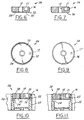
- End cap 26 includes threaded outer surface 16 and threaded inner receiving aperture 18.
- End cap 26 further includes an underside 28.
- Underside 28 has a recessed portion 30 and a strip portion 32 extending around and out from the recessed portion.
- Recessed portion 30 is recessed to a given depth.
- Other end caps useable with cylindrical cavity 12 have recessed portions recessed to different depths.
- Recessed portion 30 and strip portion 32 define a determined geometric configuration of underside 28. The determined geometric configuration causes cylindrical cavity 12 to have certain electrical response characteristics independent of the axial position of end cap 26 within the cavity.
- End cap 34 includes threaded outer surface 16 and threaded inner receiving aperture 18.
- End cap 34 further includes an underside 36.
- underside 36 does not include a recessed portion.
- underside 36 defines a determined geometric configuration. The determined geometric configuration causes cylindrical cavity 12 to have certain electrical response characteristics independent of the axial position of end cap 34 within the cavity.
- End cap 34 like end cap 26, preferably includes a cavity outgassing port 38.
- the electrical response of cylindrical cavity 12 can be changed by the end caps with different undersides.
- the electrical response of cylindrical cavity 12 can be altered by simply choosing an end cap 14 with a suitable underside and then position the end cap to a predetermined axial position.
- the axial position of end cap 14 can be changed to change the electrical response of cylindrical cavity 12.
- a ridge such as strip portion 32 may be on projection 24 of cylindrical cavity 12 for engaging with the strip portion.
- the ridge engages with strip portion 32 as end cap 26 is tightened down such that the electrical leakage of cavity 12 is decreased as a result of the higher pressure between the ridge and the strip portion.
- the present invention is applicable in many microwave applications such as satellite system input and output filter resonators and waveguides. Use of the present invention decreases weight, size, and number of piece parts typically used to form a tunable microwave cavity while improving overall electrical characteristics of the cavity.
- the present invention has been found to be valuable for devices employing the cylindrical TE 011 mode and the TE 01 ⁇ dielectric resonator mode.
Landscapes
- Control Of Motors That Do Not Use Commutators (AREA)
- Details Of Connecting Devices For Male And Female Coupling (AREA)
Applications Claiming Priority (2)
| Application Number | Priority Date | Filing Date | Title |
|---|---|---|---|
| US154488 | 1998-09-16 | ||
| US09/154,488 US6118356A (en) | 1998-09-16 | 1998-09-16 | Microwave cavity having a removable end wall |
Publications (2)
| Publication Number | Publication Date |
|---|---|
| EP0987787A2 true EP0987787A2 (fr) | 2000-03-22 |
| EP0987787A3 EP0987787A3 (fr) | 2001-08-22 |
Family
ID=22551540
Family Applications (1)
| Application Number | Title | Priority Date | Filing Date |
|---|---|---|---|
| EP99116194A Withdrawn EP0987787A3 (fr) | 1998-09-16 | 1999-08-24 | Cavité hyperfréquence avec paroi terminale démontable |
Country Status (3)
| Country | Link |
|---|---|
| US (1) | US6118356A (fr) |
| EP (1) | EP0987787A3 (fr) |
| CA (1) | CA2281150C (fr) |
Cited By (3)
| Publication number | Priority date | Publication date | Assignee | Title |
|---|---|---|---|---|
| EP1935485A1 (fr) * | 2006-12-21 | 2008-06-25 | Biotage AB | Réacteur pour système de chauffage d'un micro-onde |
| WO2008074799A1 (fr) * | 2006-12-21 | 2008-06-26 | Biotage Ab | Récipient de réaction pour un système de chauffage par micro-ondes |
| WO2009027720A1 (fr) * | 2007-08-31 | 2009-03-05 | Bae Systems Plc | Oscillateurs résonants diélectriques à faibles vibrations |
Families Citing this family (6)
| Publication number | Priority date | Publication date | Assignee | Title |
|---|---|---|---|---|
| DE10010967A1 (de) * | 2000-03-07 | 2001-09-13 | Bosch Gmbh Robert | Hohlraumresonator mit abstimmbarer Resonanzfrequenz |
| SE517746C2 (sv) * | 2000-10-20 | 2002-07-09 | Ericsson Telefon Ab L M | Lageranordning, Kavitetsfilter samt förfarande för montering därav |
| US7034266B1 (en) | 2005-04-27 | 2006-04-25 | Kimberly-Clark Worldwide, Inc. | Tunable microwave apparatus |
| US8884723B2 (en) * | 2010-06-02 | 2014-11-11 | Com Dev International Ltd. | TE011 cavity filter assembly |
| US10454149B2 (en) | 2016-11-08 | 2019-10-22 | LDS Innovations LLC | Tuning and measurement fixtures for ceramic filters |
| EP3660977B1 (fr) * | 2018-11-30 | 2023-12-13 | Nokia Solutions and Networks Oy | Résonateur pour signaux de fréquence radio |
Family Cites Families (22)
| Publication number | Priority date | Publication date | Assignee | Title |
|---|---|---|---|---|
| US2890421A (en) * | 1953-02-26 | 1959-06-09 | Univ California | Microwave cavity filter |
| US3202944A (en) * | 1962-04-09 | 1965-08-24 | Varian Associates | Cavity resonator apparatus |
| US3247475A (en) * | 1963-09-06 | 1966-04-19 | Motorola Inc | Helical resonator with variable capacitor having fixed plate which also functions as inductance |
| US3618135A (en) * | 1970-02-06 | 1971-11-02 | Avco Corp | Variable capacitor of the locking type |
| US3771074A (en) * | 1972-03-20 | 1973-11-06 | Nasa | Tunable cavity resonator with ramp shaped supports |
| US4035749A (en) * | 1976-04-06 | 1977-07-12 | Harvard Industries, Inc. | Microwave tuning screw assembly having positive shorting |
| AU3500078A (en) * | 1977-04-21 | 1979-10-18 | Del Technology Ltd | Coaxial resonator tuning |
| US4241322A (en) * | 1979-09-24 | 1980-12-23 | Bell Telephone Laboratories, Incorporated | Compact microwave filter with dielectric resonator |
| US4360793A (en) * | 1981-04-02 | 1982-11-23 | Rhodes John D | Extracted pole filter |
| US4410865A (en) * | 1982-02-24 | 1983-10-18 | Hughes Aircraft Company | Spherical cavity microwave filter |
| US4494093A (en) * | 1982-11-01 | 1985-01-15 | Gte Communications Systems Corporation | Lockable tuning mechanism with reduced backlash |
| GB8323143D0 (en) * | 1983-08-27 | 1983-09-28 | Oxley R F | Tuning screw |
| US4728913A (en) * | 1985-01-18 | 1988-03-01 | Murata Manufacturing Co., Ltd. | Dielectric resonator |
| US4639690A (en) * | 1985-07-05 | 1987-01-27 | Litton Systems, Inc. | Tunable, dielectric-resonator-stabilized oscillator and method of tuning same |
| IT1185323B (it) * | 1985-07-29 | 1987-11-12 | Gte Telecom Spa | Cavita' metallica a microonde |
| US4673894A (en) * | 1986-04-10 | 1987-06-16 | California Microwave, Incorporated | Oscillator coupled through cylindrical cavity for generating low noise microwaves |
| SU1555727A1 (ru) * | 1987-06-23 | 1990-04-07 | Московский государственный педагогический институт им.В.И.Ленина | Фильтр |
| JPH01151302A (ja) * | 1987-12-08 | 1989-06-14 | Toyo Commun Equip Co Ltd | 誘電体共振器 |
| FR2655199B1 (fr) * | 1989-11-30 | 1992-10-02 | Alcatel Transmission | Filtre eliminateur de bande pour guide d'ondes hyperfrequences. |
| US5218330A (en) * | 1990-05-18 | 1993-06-08 | Fujitsu Limited | Apparatus and method for easily adjusting the resonant frequency of a dielectric TEM resonator |
| US5243310A (en) * | 1992-01-27 | 1993-09-07 | The United States Of America As Represented By The Administrator Of The National Aeronautics And Space Administration | Three point lead screw positioning apparatus for a cavity tuning plate |
| US5825267A (en) * | 1997-07-24 | 1998-10-20 | Allen Telecom Inc. | Filter tuning assmebly |
-
1998
- 1998-09-16 US US09/154,488 patent/US6118356A/en not_active Expired - Fee Related
-
1999
- 1999-08-24 EP EP99116194A patent/EP0987787A3/fr not_active Withdrawn
- 1999-08-30 CA CA002281150A patent/CA2281150C/fr not_active Expired - Fee Related
Cited By (3)
| Publication number | Priority date | Publication date | Assignee | Title |
|---|---|---|---|---|
| EP1935485A1 (fr) * | 2006-12-21 | 2008-06-25 | Biotage AB | Réacteur pour système de chauffage d'un micro-onde |
| WO2008074799A1 (fr) * | 2006-12-21 | 2008-06-26 | Biotage Ab | Récipient de réaction pour un système de chauffage par micro-ondes |
| WO2009027720A1 (fr) * | 2007-08-31 | 2009-03-05 | Bae Systems Plc | Oscillateurs résonants diélectriques à faibles vibrations |
Also Published As
| Publication number | Publication date |
|---|---|
| US6118356A (en) | 2000-09-12 |
| CA2281150A1 (fr) | 2001-02-28 |
| CA2281150C (fr) | 2002-01-29 |
| EP0987787A3 (fr) | 2001-08-22 |
Similar Documents
| Publication | Publication Date | Title |
|---|---|---|
| US5777534A (en) | Inductor ring for providing tuning and coupling in a microwave dielectric resonator filter | |
| US4037182A (en) | Microwave tuning device | |
| US7310031B2 (en) | Dielectric resonators and circuits made therefrom | |
| US6002311A (en) | Dielectric TM mode resonator for RF filters | |
| US7057480B2 (en) | Cross-coupled dielectric resonator circuit | |
| US4521754A (en) | Tuning and temperature compensation arrangement for microwave resonators | |
| US7352264B2 (en) | Electronically tunable dielectric resonator circuits | |
| KR101685099B1 (ko) | 세라믹 공진기를 포함하는 캐비티 필터 | |
| CA2216158A1 (fr) | Filtre a resonateurs dielectriques | |
| US5373270A (en) | Multi-cavity dielectric filter | |
| US6118356A (en) | Microwave cavity having a removable end wall | |
| EP0316813B1 (fr) | Résonateur diélectrique | |
| US4630012A (en) | Ring shaped dielectric resonator with adjustable tuning screw extending upwardly into ring opening | |
| US4124830A (en) | Waveguide filter employing dielectric resonators | |
| US4389624A (en) | Dielectric-loaded coaxial resonator with a metal plate for wide frequency adjustments | |
| KR20010112362A (ko) | 고주파필터 | |
| US7078990B1 (en) | RF cavity resonator with low passive inter-modulation tuning element | |
| EP3384551B1 (fr) | Résonateur coaxial avec disque diélectrique | |
| US6362707B1 (en) | Easily tunable dielectrically loaded resonators | |
| WO2000038269A1 (fr) | Manchon pour filtre hf | |
| WO2006059159A1 (fr) | Filtre a resonateur dielectrique pouvant etre accorde ou reconfigure | |
| JPH01260901A (ja) | 誘電体フィルタ | |
| WO2023237183A1 (fr) | Agencement de résonateur accordable, filtre de fréquence accordable et procédé d'accord correspondant | |
| RU2709030C1 (ru) | Полосно-заграждающий фильтр | |
| US20120019339A1 (en) | Filter utilizing combination of TE and modified HE mode dielectric resonators |
Legal Events
| Date | Code | Title | Description |
|---|---|---|---|
| PUAI | Public reference made under article 153(3) epc to a published international application that has entered the european phase |
Free format text: ORIGINAL CODE: 0009012 |
|
| AK | Designated contracting states |
Kind code of ref document: A2 Designated state(s): AT BE CH CY DE DK ES FI FR GB GR IE IT LI LU MC NL PT SE |
|
| AX | Request for extension of the european patent |
Free format text: AL;LT;LV;MK;RO;SI |
|
| PUAL | Search report despatched |
Free format text: ORIGINAL CODE: 0009013 |
|
| AK | Designated contracting states |
Kind code of ref document: A3 Designated state(s): AT BE CH CY DE DK ES FI FR GB GR IE IT LI LU MC NL PT SE |
|
| AX | Request for extension of the european patent |
Free format text: AL;LT;LV;MK;RO;SI |
|
| 17P | Request for examination filed |
Effective date: 20020123 |
|
| AKX | Designation fees paid |
Free format text: DE FR GB IT |
|
| RAP1 | Party data changed (applicant data changed or rights of an application transferred) |
Owner name: THE BOEING COMPANY |
|
| 17Q | First examination report despatched |
Effective date: 20061116 |
|
| RAP1 | Party data changed (applicant data changed or rights of an application transferred) |
Owner name: L-3 COMMUNICATIONS - ELECTRON TECHNOLOGIES, INC. |
|
| RAP1 | Party data changed (applicant data changed or rights of an application transferred) |
Owner name: COM DEV USA, LLC |
|
| STAA | Information on the status of an ep patent application or granted ep patent |
Free format text: STATUS: THE APPLICATION IS DEEMED TO BE WITHDRAWN |
|
| 18D | Application deemed to be withdrawn |
Effective date: 20111029 |