EP0987790A1 - Abgeschirmter Kabelstecker und Verfahren um daran ein abgeschirmtes Kabel zu verbinden - Google Patents
Abgeschirmter Kabelstecker und Verfahren um daran ein abgeschirmtes Kabel zu verbinden Download PDFInfo
- Publication number
- EP0987790A1 EP0987790A1 EP99202938A EP99202938A EP0987790A1 EP 0987790 A1 EP0987790 A1 EP 0987790A1 EP 99202938 A EP99202938 A EP 99202938A EP 99202938 A EP99202938 A EP 99202938A EP 0987790 A1 EP0987790 A1 EP 0987790A1
- Authority
- EP
- European Patent Office
- Prior art keywords
- shielding
- hood
- cable
- outer jacket
- bodies
- Prior art date
- Legal status (The legal status is an assumption and is not a legal conclusion. Google has not performed a legal analysis and makes no representation as to the accuracy of the status listed.)
- Granted
Links
- 238000000034 method Methods 0.000 title claims abstract description 27
- 238000002788 crimping Methods 0.000 claims abstract description 6
- 239000004020 conductor Substances 0.000 claims description 15
- 239000011810 insulating material Substances 0.000 claims description 3
- 230000004323 axial length Effects 0.000 description 2
- RYGMFSIKBFXOCR-UHFFFAOYSA-N Copper Chemical compound [Cu] RYGMFSIKBFXOCR-UHFFFAOYSA-N 0.000 description 1
- 239000011889 copper foil Substances 0.000 description 1
Images






Classifications
-
- H—ELECTRICITY
- H01—ELECTRIC ELEMENTS
- H01R—ELECTRICALLY-CONDUCTIVE CONNECTIONS; STRUCTURAL ASSOCIATIONS OF A PLURALITY OF MUTUALLY-INSULATED ELECTRICAL CONNECTING ELEMENTS; COUPLING DEVICES; CURRENT COLLECTORS
- H01R9/00—Structural associations of a plurality of mutually-insulated electrical connecting elements, e.g. terminal strips or terminal blocks; Terminals or binding posts mounted upon a base or in a case; Bases therefor
- H01R9/03—Connectors arranged to contact a plurality of the conductors of a multiconductor cable, e.g. tapping connections
- H01R9/05—Connectors arranged to contact a plurality of the conductors of a multiconductor cable, e.g. tapping connections for coaxial cables
- H01R9/0518—Connection to outer conductor by crimping or by crimping ferrule
Definitions
- the invention relates to a method for connecting a connector to a shielded cable, said cable having a plurality of wires, a common shielding and an outer jacket, comprising exposing the wires and the shielding at one end of the cable, providing a first sleeve-like body on the outer jacket near the exposed shielding, laying the exposed shielding on the first body and mounting a second sleeve-like body of conductive material on the first body to thereby clamp the exposed shielding between both bodies.
- the invention further relates to a cable connector with a shielded cable and to cable connector parts to be used in the method.
- the first body is a plastic sleeve having an inner diameter sufficient to receive the outer jacket of the cable.
- the shielding generally made as braided metallic wires, is clamped between the plastic sleeve and the second conductive body.
- US-A-4 902 249 discloses a method for connecting a connector to a shielded cable, wherein an inner ferrule is mounted on the exposed shielding, the shielding is laid on the inner ferrule and the shielding laid back on the inner ferrule is covered by a conductive layer such as a copper foil.
- the invention aims to provide an improved method of the above-mentioned type.
- the method is characterized in that the first body is mounted on the outer jacket by crimping an axial section of the first body at its end directed away from the exposed shielding, and in that the second body is crimped on the first body with an axial section at its end adjacent the exposed wires covering at least partially the non-crimped section of the first body.
- the first body is fixed in position on the outer jacket before mounting the second body, whereas the second body is crimped on a non-crimped section of the first body so that a good electrical connection between the first and second bodies can be obtained without exerting high forces on the cable.
- the forces exerted on the cable for fixation of the inner body can be determined in an accurate manner to fix the inner body in position and to provide a desired strain relief of the cable through locking the body/bodies within a hood of the connector.
- a cable connector is provided with a shielded cable having a plurality of wires, a shielding and an outer jacket, said cable connector comprising a housing of insulating material accommodating a plurality of contacts connected to said wires, and a hood of conductive material connected to the cable shielding, wherein a first sleeve-like body is provided on the outer jacket and a second sleeve-like body of conductive material is mounted on the first body, the cable shielding being clamped between both bodies, characterized in that an axial section of the first body directed away from the insulating housing is crimped on the outer jacket, in that an axial section of the second body is crimped on the first body, the axial section of the second body covering at least partially the non-crimped section of the first body, and in that the bodies are received within a chamber of the hood having a stop co-operating with at least one of the bodies to lock the bodies in the hood.
- cable connector parts for use in the method of the invention comprising an insulating housing accommodating a plurality of contacts, first and second hood parts of conductive material, a first sleeve-like body and a second sleeve-like body, at least the second body being made of conductive material, characterized in that the second body comprises a cylindrical and a conical part, at least said conical part having a plurality of axial slots which are open at one end to provide a plurality of spring-type legs.
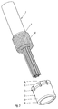
- Fig. 1 shows a shielded cable 1 having a plurality of wires 2, a common shielding 3 and an outer jacket 4.
- the shielding 3 is made of braided metallic wires.
- a first sleeve-like body 5 made of a conductive material, for example a metallic ring is slid onto the outer jacket 4 such that one end of the body 5 extends beyond the outer jacket 4 along a short distance as shown in fig. 2.
- the body is fixed in position on the outer jacket 4 by crimping an axial section 6 on the outer jacket 4. In this manner the remaining section 7 does not clamp the outer jacket 4 and remains relatively flexible.
- the exposed part 8 of the shielding 3 is laid on the inner body 5, wherein it is guaranteed that the shielding 3 will contact the inner body 5 both at the outer circumferential surface and the end extending beyond the outer jacket 4.
- a second sleeve-like outer body 9 of conductive material is slid on the inner body 5 until an inwardly directed shoulder 10 at its end near the exposed wires 2 abuts against the exposed shielding part 8 at the corresponding end of the inner body 5.
- an axial section 11 at the end of the outer body 9 near the exposed wires 2 is crimped on the exposed shielding part 8 supported by the non-crimped section 7 of the inner body 5. In this manner the shielding 3 is clamped with a high clamping force between the bodies 5, 9 without exerting high forces on the cable 1. A good electrical connection between the bodies 5, 9 and the shielding 3 is guaranteed.
- Fig. 3 and 4 further show that the second or outer body 9 has a substantially cylindrical part 12 joining the inwardly directed shoulder 10 and a conical part 13 with slots 14 providing outwardly flaring spring-type legs 15. The purpose of these legs 15 will be explained hereinafter.
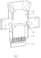
- the connector further comprises a hood including two hood parts 18, one of which is shown in fig. 6 and 7.
- the hood parts 18 are made of conductive material, wherein a covering plate 19 is mounted on one end of each hood part 18.
- the covering plate 19 is made of insulating material and covers the exposed parts of the contacts 16 when the housing 17 is mounted in the hood.
- the covering plate 19 is fixed on the hood part 18 by means of two wing parts 20 having a slot engaging oblique edges 21 of the hood part 18 and two lugs 22 engaging into openings 23 of the hood part 18.
- Each hood part 18 is provided with a semi-cylindrical chamber 24 for receiving the outer body 9.
- This chamber 24 is limited in axial direction by a first shoulder section 25 and a second shoulder section 26.
- the insulating housing 17 is mounted in the lower end of the hood part 18 whereas the second body 9 is fittingly received in the chamber 24.
- the diameter in this chamber 24 is such that the spring-type legs 15 will be forced inwardly to guarantee a good electrical connection between the outer body 9 and the hood parts 18 and thereby between the shielding 3 and the hood parts 18.
- the axial length of the chamber 24 is such that the second body 9 is locked within the chamber 24 between the shoulder sections 25, 26, so that the bodies 5, 9 provide a strain relief for the cable 1.
- the strength of the strain relief can be determined by the force used to crimp the first body 5 on the outer jacket 4.
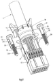
- the bolts 28 each comprise a head 31, a shaft section 32 and a screw thread section 33.
- the outer diameter of the shaft section 32 is smaller than the outer diameter of the head and screw thread section 33, respectively.
- Each bolt chamber has a passage 34 receiving the shaft section 32 with play, wherein however the diameter of the passage 34 is smaller than the outer diameter of the head 31 and screw thread section 33, respectively.
- Fig. 10-12 show an alternative embodiment of the method, connector and connector parts of the invention. Parts corresponding to the parts of the embodiment of fig. 1-9 are indicated by the same reference numerals.
- the shielded cable 1, wires 2 and shielding 3 are only schematically indicated.
- the wires 2 and shielding 3 are exposed at one end of the cable 1.
- the first body or inner ferrule 5 is mounted on the outer jacket 4 of the cable with one end extending beyond the outer jacket 4.
- the inner ferrule 5 is fixed on the cable 1 by crimping the axial section 6 on the outer jacket 4.
- the inner ferrule 5 is provided with a radially extending ring 35 at its end directed away from the exposed shielding 3.
- the second sleeve-like body or outer ferrule 9 is slid on the first body 5 until its inwardly directed shoulder 10 engages the corresponding axial end of the first body 5.
- the second body 9 is provided with slots 14 extending along the major part of the axial length of the second body 9 as shown in fig. 12, so that flexible legs 36 are obtained directed outwardly as shown in fig. 10.
- the hood parts 18 are provided with a receiving chamber 24 for the outer ferrule 9, wherein at one end a slot 37 is provided for receiving the ring 35 of the inner ferrule 5.
- the diameter A of the chamber 24 near the slot 37 is smaller than the outer diameter B of the flexible legs 36 such that when the bodies 5, 9 are mounted in the chamber 24, the flexible legs 36 of the outer body 9 are pressed against the inner body 5 thereby clamping the exposed shielding part 8 between both bodies 5, 9.
- the ring 35 is received in the slot 37 so that the first and second bodies 5, 9 are locked within the hood parts 18 and a desired strain relief is obtained.
- wires 2 can be connected to IDC-contacts 16 accommodated in an insulated housing 17 in the same manner as in the first embodiment of fig. 1-9.
- Fig. 13-16 show a third embodiment of the method, connector and connector parts of the invention. Corresponding parts are indicated by the same reference numerals.
- the shielded cable 1, the wires 2, the shielding 3 and the outer jacket 4 are shown very schematically in fig. 15 and 16.
- the wires 2 and shielding 3 are exposed at one end of the cable 1 and the same inner ferrule 5 with a radial ring 35 at one end directed away from the exposed shielding 3 is mounted on the outer jacket 4 by crimping an axial section 6 on the outer jacket 4.
- one end of the inner ferrule 5 is aligned with the end of the outer jacket 4.
- the exposed shielding part 8 is laid on the outer surface of the inner ferrule 5.
- a second sleeve-like body or outer ferrule 38 having a conical shape is used.
- the diameter of the outer ferrule 38 increases from a radially inwardly directed shoulder 39 at its end near the exposed wires 2 to the end directed away from the exposed wires.
- the inner diameter of the outer ferrule 38 near the shoulder 43 is approximately the same as the outer diameter of the inner ferrule 5.
- hood parts 40 and 41 are used, which are shown in fig. 13 and 14, respectively.
- the hood part 40 is provided with a cylindrical receiving chamber 42 having an outer diameter A which is larger than the largest outer diameter B of the outer ferrule 38.
- a shoulder 43 of the hood part 40 provides a stop for the ring 35 of the inner ferrule 5.
- the second hood part 41 is provided with a receiving chamber 44 and a slot 45 for receiving the ring 35 of the outer ferrule 5.
- the receiving chamber 44 has a conical shape corresponding to the conical shape of the outer ferrule 38, wherein the largest diameter of the receiving chamber 44 near the slot 45 corresponds to the largest diameter of the outer ferrule 38.
Landscapes
- Details Of Connecting Devices For Male And Female Coupling (AREA)
- Multi-Conductor Connections (AREA)
Applications Claiming Priority (2)
| Application Number | Priority Date | Filing Date | Title |
|---|---|---|---|
| NL1010080 | 1998-09-14 | ||
| NL1010080A NL1010080C2 (nl) | 1998-09-14 | 1998-09-14 | Werkwijze voor het aansluiten van een afgeschermde kabel op een connector, kabelconnector met een afgeschermde kabel en kabelconnectoronderdelen voor toepassing bij deze werkwijze. |
Publications (2)
| Publication Number | Publication Date |
|---|---|
| EP0987790A1 true EP0987790A1 (de) | 2000-03-22 |
| EP0987790B1 EP0987790B1 (de) | 2011-05-25 |
Family
ID=19767809
Family Applications (1)
| Application Number | Title | Priority Date | Filing Date |
|---|---|---|---|
| EP19990202938 Expired - Lifetime EP0987790B1 (de) | 1998-09-14 | 1999-09-10 | Abgeschirmter Kabelstecker und Verfahren um daran ein abgeschirmtes Kabel zu verbinden |
Country Status (2)
| Country | Link |
|---|---|
| EP (1) | EP0987790B1 (de) |
| NL (1) | NL1010080C2 (de) |
Cited By (4)
| Publication number | Priority date | Publication date | Assignee | Title |
|---|---|---|---|---|
| US6431905B2 (en) | 2000-01-31 | 2002-08-13 | Framatome Connectors International | Cable connector |
| NL1022159C2 (nl) * | 2002-12-13 | 2004-06-15 | Framatome Connectors Int | Kabelconnector en methode voor het vervaardigen van een kabelconnector. |
| CN119689045A (zh) * | 2024-12-24 | 2025-03-25 | 广东电网有限责任公司 | 屏蔽装置 |
| CN120432909A (zh) * | 2025-07-07 | 2025-08-05 | 洛阳凡讯电子科技有限公司 | 一种室内弱电箱监控安防装置的导电连接结构 |
Citations (6)
| Publication number | Priority date | Publication date | Assignee | Title |
|---|---|---|---|---|
| EP0094312A1 (de) * | 1982-05-06 | 1983-11-16 | RADIALL INDUSTRIE, Société Anonyme dite: | Winkelverbinder für Koaxialkabel |
| EP0346027A2 (de) * | 1988-06-04 | 1989-12-13 | Nippon Acchakutanshi Seizo Kabushiki Kaisha | Zusammenbau eines elektrischen Steckverbinders mit einem abgeschirmten Kabel |
| EP0391520A1 (de) * | 1989-04-03 | 1990-10-10 | Electro Adapter, Inc. | Abgeschirmte Verbindungen für einen elektrischen Kabelsteckverbinder |
| GB2241391A (en) * | 1990-02-22 | 1991-08-28 | Brand Rex Ltd | Earth continuity in electrical connector |
| WO1993005547A1 (en) * | 1991-09-05 | 1993-03-18 | Lrc Electronics, Inc. | A manually installable coaxial cable connector |
| US5342216A (en) * | 1992-10-01 | 1994-08-30 | The Whitaker Corporation | Jackscrew mechanism |
-
1998
- 1998-09-14 NL NL1010080A patent/NL1010080C2/nl not_active IP Right Cessation
-
1999
- 1999-09-10 EP EP19990202938 patent/EP0987790B1/de not_active Expired - Lifetime
Patent Citations (6)
| Publication number | Priority date | Publication date | Assignee | Title |
|---|---|---|---|---|
| EP0094312A1 (de) * | 1982-05-06 | 1983-11-16 | RADIALL INDUSTRIE, Société Anonyme dite: | Winkelverbinder für Koaxialkabel |
| EP0346027A2 (de) * | 1988-06-04 | 1989-12-13 | Nippon Acchakutanshi Seizo Kabushiki Kaisha | Zusammenbau eines elektrischen Steckverbinders mit einem abgeschirmten Kabel |
| EP0391520A1 (de) * | 1989-04-03 | 1990-10-10 | Electro Adapter, Inc. | Abgeschirmte Verbindungen für einen elektrischen Kabelsteckverbinder |
| GB2241391A (en) * | 1990-02-22 | 1991-08-28 | Brand Rex Ltd | Earth continuity in electrical connector |
| WO1993005547A1 (en) * | 1991-09-05 | 1993-03-18 | Lrc Electronics, Inc. | A manually installable coaxial cable connector |
| US5342216A (en) * | 1992-10-01 | 1994-08-30 | The Whitaker Corporation | Jackscrew mechanism |
Cited By (7)
| Publication number | Priority date | Publication date | Assignee | Title |
|---|---|---|---|---|
| US6431905B2 (en) | 2000-01-31 | 2002-08-13 | Framatome Connectors International | Cable connector |
| NL1022159C2 (nl) * | 2002-12-13 | 2004-06-15 | Framatome Connectors Int | Kabelconnector en methode voor het vervaardigen van een kabelconnector. |
| WO2004055942A1 (en) * | 2002-12-13 | 2004-07-01 | Fci | Cable connector and method for assembling such a connector |
| CN100367567C (zh) * | 2002-12-13 | 2008-02-06 | Fci公司 | 电缆连接器和用于组装该连接器的方法 |
| US7476129B2 (en) | 2002-12-13 | 2009-01-13 | Fci | Cable connector and method for assembling such a connector |
| CN119689045A (zh) * | 2024-12-24 | 2025-03-25 | 广东电网有限责任公司 | 屏蔽装置 |
| CN120432909A (zh) * | 2025-07-07 | 2025-08-05 | 洛阳凡讯电子科技有限公司 | 一种室内弱电箱监控安防装置的导电连接结构 |
Also Published As
| Publication number | Publication date |
|---|---|
| EP0987790B1 (de) | 2011-05-25 |
| NL1010080C2 (nl) | 2000-03-15 |
Similar Documents
| Publication | Publication Date | Title |
|---|---|---|
| EP0986135B1 (de) | Abgeschirmter Kabelstecker und Verfahren um daran ein abgeschirmtes Kabel zu verbinden | |
| EP0907221B1 (de) | Elektrischer Kabelsteckverbinder | |
| EP0001701B1 (de) | Elektrischer Endverbinder für ein Koaxialkabel | |
| US6153830A (en) | Connector and method of operation | |
| US6517379B2 (en) | Plug connector | |
| US7140912B2 (en) | Triaxial connector and method | |
| US4272148A (en) | Shielded connector housing for use with a multiconductor shielded cable | |
| US6019615A (en) | Construction of and method of processing end portion of shielded cable | |
| CA1286743C (en) | Shielded connector | |
| EP0694989B1 (de) | Anschlussstruktur eines abgeschirmten Kabels und dessen Anschlussverfahren | |
| US7056148B2 (en) | Electrical terminal connection, especially for connecting an outer conductor of a coaxial cable | |
| GB2085676A (en) | Connector element for an armoured cable with two multi-core conductors | |
| EP2452402A1 (de) | Hochfester elektrischer steckverbinder | |
| US6896549B2 (en) | Device for connecting coaxial conductors to a plug-in connector | |
| US6048227A (en) | Connector backshell | |
| US4468080A (en) | Cable shield termination means for plug and receptacle connectors | |
| US6227881B1 (en) | Cable management coupling and shielding interconnect system and method | |
| EP0987790B1 (de) | Abgeschirmter Kabelstecker und Verfahren um daran ein abgeschirmtes Kabel zu verbinden | |
| EP0913900B1 (de) | Kabelklemmvorrichtung | |
| AU602900B2 (en) | Branch connector for coaxial cable | |
| EP0991138A2 (de) | Elektrischer Verbinder mit Erdungsvorrichtung | |
| CN117438815A (zh) | 屏蔽弹簧触头、插入式连接器和插入式连接器系统 | |
| JP2681430B2 (ja) | 電気ケーブルの接続部構造 | |
| JP3012286U (ja) | 同軸ケーブルコネクタ | |
| EP0980118A2 (de) | Kabelabschirmungsanschluss |
Legal Events
| Date | Code | Title | Description |
|---|---|---|---|
| PUAI | Public reference made under article 153(3) epc to a published international application that has entered the european phase |
Free format text: ORIGINAL CODE: 0009012 |
|
| AK | Designated contracting states |
Kind code of ref document: A1 Designated state(s): BE DE FR GB IE SE |
|
| AX | Request for extension of the european patent |
Free format text: AL;LT;LV;MK;RO;SI |
|
| 17P | Request for examination filed |
Effective date: 20000816 |
|
| AKX | Designation fees paid |
Free format text: BE DE FR GB IE SE |
|
| GRAP | Despatch of communication of intention to grant a patent |
Free format text: ORIGINAL CODE: EPIDOSNIGR1 |
|
| GRAC | Information related to communication of intention to grant a patent modified |
Free format text: ORIGINAL CODE: EPIDOSCIGR1 |
|
| GRAS | Grant fee paid |
Free format text: ORIGINAL CODE: EPIDOSNIGR3 |
|
| RAP1 | Party data changed (applicant data changed or rights of an application transferred) |
Owner name: FCI |
|
| GRAA | (expected) grant |
Free format text: ORIGINAL CODE: 0009210 |
|
| AK | Designated contracting states |
Kind code of ref document: B1 Designated state(s): BE DE FR GB IE SE |
|
| REG | Reference to a national code |
Ref country code: GB Ref legal event code: FG4D |
|
| REG | Reference to a national code |
Ref country code: IE Ref legal event code: FG4D |
|
| REG | Reference to a national code |
Ref country code: DE Ref legal event code: R096 Ref document number: 69943450 Country of ref document: DE Effective date: 20110707 |
|
| REG | Reference to a national code |
Ref country code: SE Ref legal event code: TRGR |
|
| PG25 | Lapsed in a contracting state [announced via postgrant information from national office to epo] |
Ref country code: BE Free format text: LAPSE BECAUSE OF FAILURE TO SUBMIT A TRANSLATION OF THE DESCRIPTION OR TO PAY THE FEE WITHIN THE PRESCRIBED TIME-LIMIT Effective date: 20110525 |
|
| PLBI | Opposition filed |
Free format text: ORIGINAL CODE: 0009260 |
|
| PLAX | Notice of opposition and request to file observation + time limit sent |
Free format text: ORIGINAL CODE: EPIDOSNOBS2 |
|
| 26 | Opposition filed |
Opponent name: VOLEX PLC Effective date: 20120227 |
|
| REG | Reference to a national code |
Ref country code: DE Ref legal event code: R026 Ref document number: 69943450 Country of ref document: DE Effective date: 20120227 |
|
| PLAF | Information modified related to communication of a notice of opposition and request to file observations + time limit |
Free format text: ORIGINAL CODE: EPIDOSCOBS2 |
|
| PLBB | Reply of patent proprietor to notice(s) of opposition received |
Free format text: ORIGINAL CODE: EPIDOSNOBS3 |
|
| PLBP | Opposition withdrawn |
Free format text: ORIGINAL CODE: 0009264 |
|
| PLBD | Termination of opposition procedure: decision despatched |
Free format text: ORIGINAL CODE: EPIDOSNOPC1 |
|
| PLBM | Termination of opposition procedure: date of legal effect published |
Free format text: ORIGINAL CODE: 0009276 |
|
| STAA | Information on the status of an ep patent application or granted ep patent |
Free format text: STATUS: OPPOSITION PROCEDURE CLOSED |
|
| 27C | Opposition proceedings terminated |
Effective date: 20130302 |
|
| REG | Reference to a national code |
Ref country code: GB Ref legal event code: 732E Free format text: REGISTERED BETWEEN 20141009 AND 20141015 |
|
| REG | Reference to a national code |
Ref country code: DE Ref legal event code: R081 Ref document number: 69943450 Country of ref document: DE Owner name: FCI ASIA PTE. LTD, SG Free format text: FORMER OWNER: FRAMATOME CONNECTORS INTERNATIONAL, COURBEVOIE, FR Effective date: 20110428 Ref country code: DE Ref legal event code: R081 Ref document number: 69943450 Country of ref document: DE Owner name: FCI ASIA PTE. LTD, SG Free format text: FORMER OWNER: FCI, GUYANCOURT, FR Effective date: 20150113 |
|
| REG | Reference to a national code |
Ref country code: FR Ref legal event code: PLFP Year of fee payment: 18 |
|
| PGFP | Annual fee paid to national office [announced via postgrant information from national office to epo] |
Ref country code: IE Payment date: 20160826 Year of fee payment: 18 Ref country code: GB Payment date: 20160830 Year of fee payment: 18 |
|
| PGFP | Annual fee paid to national office [announced via postgrant information from national office to epo] |
Ref country code: SE Payment date: 20160908 Year of fee payment: 18 Ref country code: FR Payment date: 20160817 Year of fee payment: 18 |
|
| PGFP | Annual fee paid to national office [announced via postgrant information from national office to epo] |
Ref country code: DE Payment date: 20160928 Year of fee payment: 18 |
|
| REG | Reference to a national code |
Ref country code: DE Ref legal event code: R119 Ref document number: 69943450 Country of ref document: DE |
|
| REG | Reference to a national code |
Ref country code: SE Ref legal event code: EUG |
|
| GBPC | Gb: european patent ceased through non-payment of renewal fee |
Effective date: 20170910 |
|
| REG | Reference to a national code |
Ref country code: IE Ref legal event code: MM4A |
|
| REG | Reference to a national code |
Ref country code: FR Ref legal event code: ST Effective date: 20180531 |
|
| PG25 | Lapsed in a contracting state [announced via postgrant information from national office to epo] |
Ref country code: DE Free format text: LAPSE BECAUSE OF NON-PAYMENT OF DUE FEES Effective date: 20180404 Ref country code: GB Free format text: LAPSE BECAUSE OF NON-PAYMENT OF DUE FEES Effective date: 20170910 Ref country code: IE Free format text: LAPSE BECAUSE OF NON-PAYMENT OF DUE FEES Effective date: 20170910 |
|
| PG25 | Lapsed in a contracting state [announced via postgrant information from national office to epo] |
Ref country code: FR Free format text: LAPSE BECAUSE OF NON-PAYMENT OF DUE FEES Effective date: 20171002 |
|
| PG25 | Lapsed in a contracting state [announced via postgrant information from national office to epo] |
Ref country code: SE Free format text: LAPSE BECAUSE OF NON-PAYMENT OF DUE FEES Effective date: 20170911 |