EP0987792A2 - Steckverbinder für Leiterplattenmontage - Google Patents
Steckverbinder für Leiterplattenmontage Download PDFInfo
- Publication number
- EP0987792A2 EP0987792A2 EP99118304A EP99118304A EP0987792A2 EP 0987792 A2 EP0987792 A2 EP 0987792A2 EP 99118304 A EP99118304 A EP 99118304A EP 99118304 A EP99118304 A EP 99118304A EP 0987792 A2 EP0987792 A2 EP 0987792A2
- Authority
- EP
- European Patent Office
- Prior art keywords
- board
- housing
- circuit board
- electrical connector
- center line
- Prior art date
- Legal status (The legal status is an assumption and is not a legal conclusion. Google has not performed a legal analysis and makes no representation as to the accuracy of the status listed.)
- Withdrawn
Links
- 230000014759 maintenance of location Effects 0.000 claims abstract description 34
- 230000037431 insertion Effects 0.000 claims abstract description 5
- 238000003780 insertion Methods 0.000 claims abstract description 5
- 239000002184 metal Substances 0.000 claims description 5
- 239000004033 plastic Substances 0.000 claims description 5
- 239000000463 material Substances 0.000 claims description 3
- 239000002991 molded plastic Substances 0.000 claims 1
- 230000013011 mating Effects 0.000 description 11
- 230000000295 complement effect Effects 0.000 description 1
- 239000003989 dielectric material Substances 0.000 description 1
- 239000007769 metal material Substances 0.000 description 1
- 230000000717 retained effect Effects 0.000 description 1
- 238000005476 soldering Methods 0.000 description 1
Images

Classifications
-
- H—ELECTRICITY
- H01—ELECTRIC ELEMENTS
- H01R—ELECTRICALLY-CONDUCTIVE CONNECTIONS; STRUCTURAL ASSOCIATIONS OF A PLURALITY OF MUTUALLY-INSULATED ELECTRICAL CONNECTING ELEMENTS; COUPLING DEVICES; CURRENT COLLECTORS
- H01R13/00—Details of coupling devices of the kinds covered by groups H01R12/70 or H01R24/00 - H01R33/00
- H01R13/648—Protective earth or shield arrangements on coupling devices, e.g. anti-static shielding
- H01R13/6485—Electrostatic discharge protection
-
- H—ELECTRICITY
- H01—ELECTRIC ELEMENTS
- H01R—ELECTRICALLY-CONDUCTIVE CONNECTIONS; STRUCTURAL ASSOCIATIONS OF A PLURALITY OF MUTUALLY-INSULATED ELECTRICAL CONNECTING ELEMENTS; COUPLING DEVICES; CURRENT COLLECTORS
- H01R12/00—Structural associations of a plurality of mutually-insulated electrical connecting elements, specially adapted for printed circuits, e.g. printed circuit boards [PCB], flat or ribbon cables, or like generally planar structures, e.g. terminal strips, terminal blocks; Coupling devices specially adapted for printed circuits, flat or ribbon cables, or like generally planar structures; Terminals specially adapted for contact with, or insertion into, printed circuits, flat or ribbon cables, or like generally planar structures
- H01R12/50—Fixed connections
- H01R12/51—Fixed connections for rigid printed circuits or like structures
- H01R12/52—Fixed connections for rigid printed circuits or like structures connecting to other rigid printed circuits or like structures
-
- H—ELECTRICITY
- H01—ELECTRIC ELEMENTS
- H01R—ELECTRICALLY-CONDUCTIVE CONNECTIONS; STRUCTURAL ASSOCIATIONS OF A PLURALITY OF MUTUALLY-INSULATED ELECTRICAL CONNECTING ELEMENTS; COUPLING DEVICES; CURRENT COLLECTORS
- H01R12/00—Structural associations of a plurality of mutually-insulated electrical connecting elements, specially adapted for printed circuits, e.g. printed circuit boards [PCB], flat or ribbon cables, or like generally planar structures, e.g. terminal strips, terminal blocks; Coupling devices specially adapted for printed circuits, flat or ribbon cables, or like generally planar structures; Terminals specially adapted for contact with, or insertion into, printed circuits, flat or ribbon cables, or like generally planar structures
- H01R12/70—Coupling devices
- H01R12/71—Coupling devices for rigid printing circuits or like structures
- H01R12/712—Coupling devices for rigid printing circuits or like structures co-operating with the surface of the printed circuit or with a coupling device exclusively provided on the surface of the printed circuit
- H01R12/716—Coupling device provided on the PCB
-
- H—ELECTRICITY
- H01—ELECTRIC ELEMENTS
- H01R—ELECTRICALLY-CONDUCTIVE CONNECTIONS; STRUCTURAL ASSOCIATIONS OF A PLURALITY OF MUTUALLY-INSULATED ELECTRICAL CONNECTING ELEMENTS; COUPLING DEVICES; CURRENT COLLECTORS
- H01R12/00—Structural associations of a plurality of mutually-insulated electrical connecting elements, specially adapted for printed circuits, e.g. printed circuit boards [PCB], flat or ribbon cables, or like generally planar structures, e.g. terminal strips, terminal blocks; Coupling devices specially adapted for printed circuits, flat or ribbon cables, or like generally planar structures; Terminals specially adapted for contact with, or insertion into, printed circuits, flat or ribbon cables, or like generally planar structures
- H01R12/70—Coupling devices
- H01R12/7005—Guiding, mounting, polarizing or locking means; Extractors
- H01R12/7011—Locking or fixing a connector to a PCB
- H01R12/7017—Snap means
- H01R12/7029—Snap means not integral with the coupling device
-
- H—ELECTRICITY
- H01—ELECTRIC ELEMENTS
- H01R—ELECTRICALLY-CONDUCTIVE CONNECTIONS; STRUCTURAL ASSOCIATIONS OF A PLURALITY OF MUTUALLY-INSULATED ELECTRICAL CONNECTING ELEMENTS; COUPLING DEVICES; CURRENT COLLECTORS
- H01R12/00—Structural associations of a plurality of mutually-insulated electrical connecting elements, specially adapted for printed circuits, e.g. printed circuit boards [PCB], flat or ribbon cables, or like generally planar structures, e.g. terminal strips, terminal blocks; Coupling devices specially adapted for printed circuits, flat or ribbon cables, or like generally planar structures; Terminals specially adapted for contact with, or insertion into, printed circuits, flat or ribbon cables, or like generally planar structures
- H01R12/70—Coupling devices
- H01R12/7005—Guiding, mounting, polarizing or locking means; Extractors
- H01R12/7011—Locking or fixing a connector to a PCB
- H01R12/7064—Press fitting
Definitions
- This invention generally relates to the art of electrical connectors and, particularly, to an electrical connector for mounting on a circuit board.
- a conventional circuit board mounted electrical connector includes a dielectric housing mounting a plurality of terminals for connection to appropriate circuit traces on the circuit board.
- the housing typically includes one or more board retention members, such as mounting pegs or posts or other boardlock members to hold the housing mounted on a surface of the board.
- the housing may be molded of plastic material, with the board retention member comprising a peg or post integral with the housing and projecting from a mounting face thereof for insertion into an appropriate mounting hole in the circuit board.
- the connector may include one or more separate board retention members, such as metal boardlocks, mounted on the plastic housing and projecting into mounting holes in the circuit board.
- the present invention is directed to solving these problems by providing an electrical connector structure which allows for connectors to be mounted directly on opposite sides of a circuit board notwithstanding the fact that one or both of the connectors include board retention members extending into or through mounting holes in the circuit board.
- An object, therefore, of the invention is to provide a new and improved electrical connector for mounting on a circuit board and allowing connectors to be mounted directly on opposite sides of the board.
- the connector includes a dielectric housing having a board mounting face. At least one board retention member projects from the board mounting face for insertion into an appropriate mounting hole in the circuit board. A recess is formed in the board mounting face for accommodating a board retention member projecting into the circuit board from a connecting device mounted on an opposite side of the circuit board.
- the dielectric housing is elongated, defining a longitudinal center line.
- the board retention member is located on one side of the center line, and the recess is located on the opposite side of the center line.
- a pair of the board retention members are spaced longitudinally of the housing and are located on opposite sides of the center line.
- a pair of the recesses also are spaced longitudinally of the housing and are located on opposite sides of the center line in alignment opposite the board retention members.
- the board retention member(s) may be a peg molded integral with the housing or the board retention member(s) may be a metal member mounted on the plastic housing.
- the concepts of the invention lend themselves appropriately for providing a hermaphroditic connector whereby the board retention member(s) and the recess(es) are located so that identical electrical connectors can be mounted on both sides of the circuit board immediately opposite each other.
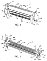
- an electrical connector is designed for mounting on one side of a circuit board, such as a printed circuit board, backplane or the like, as shown hereinafter.
- the connector includes a one-piece dielectric housing, generally designated 12, which can be unitarily molded of dielectric material such as plastic or the like.
- the housing is elongated and defines a longitudinal center line 14 (Fig. 2).
- the housing has a mating portion 16 defining a mating face 16a opposite a board mounting face defined by board-mounting surfaces 18a and 18b.
- the housing mounts a plurality of terminals in two rows, the terminals having contact portions 20 inside opposite side walls of mating portion 16, along with right-angled tail portions 22 for surface mounting to appropriate circuit traces on the circuit board.
- Board-mounting surfaces 18a are elongated in the direction of center line 14.
- Board-mounting surfaces 18b are elongated transversely of the center line.
- a pair of the board-mounting surfaces 18a are provided and located at opposite ends of the housing and spaced on opposite sides of the center line.
- a pair of the board-mounting surfaces 18b are provided and are located at opposite ends of the housing and spaced on opposite sides of the center line.
- housing 12 includes a pair of wing portions 24 spaced outside opposite ends of mating portion 16 and between which a complementary mating connector (not shown) is inserted.
- the mating connector will have a receptacle for receiving mating portion 16, along with a tongue for insertion into an elongated slot 25 (Fig. 1) within mating portion 16.
- Appropriate terminals of the mating connector will have contact portions on opposite sides of the tongue for engaging contact portions 20 inside the side walls of mating portion 16.
- Housing 12 of connector 10 includes a pair of integrally molded board retention members or pegs 26 which project from board-mounting surfaces 18a of the housing.
- the pegs have small, longitudinal ribs 26a which can be crushed when inserted into the mounting holes in the circuit board to provide a tight interference fit between the pegs and the holes.
- one of the pair of mounting pegs 16 is disposed at each opposite end of the longitudinal housing and on each opposite side of center line 14.
- Housing 12 of connector 10 also includes a pair of recesses 28 in the mounting face of the housing for accommodating board retention members projecting through the circuit board from a connecting device mounted on the opposite side of the board, as will be seen hereinafter.
- recesses 28 are located at opposite ends of the housing and on opposite sides of center line 14 adjacent board mounting surfaces 18b. The recesses are aligned transversely on opposite sides of the center line from board retention posts 26.
- An elongated tail aligner 30 includes a plurality of passages through which tails 22 of the terminals extend.
- the aligner maintains proper spacing or pitch for the terminals.
- the tail aligner is press-fit into sockets 32 (Fig. 2) in the bottom of housing 12 and is retained therein either by a press-fit or by the addition of an adhering medium.
- Connector 10 also includes an electrostatic discharge clip 34 (Fig. 1) mounted within each wing 24 at each end of the housing.
- the electrostatic discharge clip is of metal material and is located for engaging appropriate grounding contacts on the mating connector.
- the electrostatic discharge clips extend downwardly through the housing and terminate in U-shaped feet 34a for surface connection to appropriate grounding pads on the circuit board, as by soldering. Therefore, the electrostatic discharge clip performs an additional function of acting as a "fitting nail" to hold the connector to the circuit board.
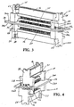
- Figures 3-5 show connector 10 mounted on a top side 36a of a circuit board 36. It can be seen that board retention pegs 26 project entirely through the circuit board.
- a second connector, generally designated 10A, is mounted to a bottom or opposite side 36b of the circuit board.
- Connector 10A differs from connector 10 only in that connector 10A has independent metal board retention members or boardlocks 26A projecting upwardly through the circuit board. Otherwise, the two connectors are substantially identical and like reference numerals have been applied to the components of connector 10A corresponding to the description of connector 10, above, in relation to Figures 1 and 2.
- Figures 3-5 clearly show how recesses 28 of both connectors 10 and 10A are aligned or in registry with board retention pegs 26 and boardlocks 26A when the connectors are mounted on opposite sides of the circuit board directly opposite each other.
- the recesses of one connector accommodate the board retention members projecting through the board from the other connector.
- Figures 6 and 7 show how the concepts of the invention save considerably space or "real estate" on circuit board 36.
- Connectors 40 have integral board retention pegs 44 similar to retention pegs 26 of connector 10.
- Connectors 42 have metal boardlocks 46 similar to boardlocks 26A of connector 10A.
- none of the connectors 40 or 42 have any recesses for accommodating the retention pegs or boardlocks projecting through the board from the opposite side thereof. Therefore, the connectors must be staggered as shown in Figure 6, and it is not possible to mount two connectors directly opposite each other on opposite sides of the circuit board.
- Figure 7 a comparison of Figure 7 can be made with the arrangement of Figure 6 to clearly see the space-saving aspects of the invention.
- three connectors 10 according to the invention are mounted on one side 36a of the circuit board directly opposite three respective connectors 10A on the opposite side 36b of the circuit board.
- board retention pegs 26 and boardlocks 26a of all of the connectors project into recesses 28 of the connector immediately on the opposite side of the circuit board.
- six connectors are mounted on the circuit board in Figure 7 within the same space as only four connectors in Figure 6. In fact, if the pairs of connectors shown in Figure 7 are mounted closer together than that shown therein, still additional space is saved on the circuit board.
Landscapes
- Coupling Device And Connection With Printed Circuit (AREA)
- Details Of Connecting Devices For Male And Female Coupling (AREA)
Applications Claiming Priority (2)
| Application Number | Priority Date | Filing Date | Title |
|---|---|---|---|
| SG9803661 | 1998-09-15 | ||
| SG9803661A SG106555A1 (en) | 1998-09-15 | 1998-09-15 | Circuit board mounted electrical connector |
Publications (2)
| Publication Number | Publication Date |
|---|---|
| EP0987792A2 true EP0987792A2 (de) | 2000-03-22 |
| EP0987792A3 EP0987792A3 (de) | 2000-10-18 |
Family
ID=20430095
Family Applications (1)
| Application Number | Title | Priority Date | Filing Date |
|---|---|---|---|
| EP99118304A Withdrawn EP0987792A3 (de) | 1998-09-15 | 1999-09-15 | Steckverbinder für Leiterplattenmontage |
Country Status (6)
| Country | Link |
|---|---|
| EP (1) | EP0987792A3 (de) |
| JP (1) | JP3213891B2 (de) |
| KR (1) | KR20000023154A (de) |
| CN (1) | CN1254209A (de) |
| SG (1) | SG106555A1 (de) |
| TW (1) | TW427581U (de) |
Cited By (1)
| Publication number | Priority date | Publication date | Assignee | Title |
|---|---|---|---|---|
| US12341276B2 (en) | 2019-05-09 | 2025-06-24 | Intel Corporation | Memory module connector |
Families Citing this family (2)
| Publication number | Priority date | Publication date | Assignee | Title |
|---|---|---|---|---|
| JP4621039B2 (ja) * | 2005-02-22 | 2011-01-26 | 株式会社日立製作所 | ディスク装置 |
| US7891989B2 (en) * | 2009-06-18 | 2011-02-22 | J. S. T. Corporation | Electrical connector and electrical connector housing |
Family Cites Families (4)
| Publication number | Priority date | Publication date | Assignee | Title |
|---|---|---|---|---|
| US5230638A (en) * | 1992-08-12 | 1993-07-27 | Molex Incorporated | Surface mounted electrical connector for printed circuit boards |
| US5482474A (en) * | 1994-05-17 | 1996-01-09 | The Whitaker Corporation | Edge-mountable circuit board connector |
| US5634810A (en) * | 1995-03-22 | 1997-06-03 | Molex Incorporated | Printed circuit board mounted electrical connector assembly |
| US5697812A (en) * | 1996-06-14 | 1997-12-16 | Molex Incorporated | Board-mounted electrical connector |
-
1998
- 1998-09-15 SG SG9803661A patent/SG106555A1/en unknown
-
1999
- 1999-09-14 JP JP30001999A patent/JP3213891B2/ja not_active Expired - Fee Related
- 1999-09-14 CN CN99122149A patent/CN1254209A/zh active Pending
- 1999-09-15 EP EP99118304A patent/EP0987792A3/de not_active Withdrawn
- 1999-09-15 KR KR1019990039456A patent/KR20000023154A/ko not_active Ceased
- 1999-09-23 TW TW088216258U patent/TW427581U/zh not_active IP Right Cessation
Cited By (1)
| Publication number | Priority date | Publication date | Assignee | Title |
|---|---|---|---|---|
| US12341276B2 (en) | 2019-05-09 | 2025-06-24 | Intel Corporation | Memory module connector |
Also Published As
| Publication number | Publication date |
|---|---|
| JP2000138080A (ja) | 2000-05-16 |
| TW427581U (en) | 2001-03-21 |
| JP3213891B2 (ja) | 2001-10-02 |
| KR20000023154A (ko) | 2000-04-25 |
| SG106555A1 (en) | 2004-10-29 |
| EP0987792A3 (de) | 2000-10-18 |
| CN1254209A (zh) | 2000-05-24 |
Similar Documents
| Publication | Publication Date | Title |
|---|---|---|
| US5269694A (en) | Surface mount electrical connector | |
| US5259793A (en) | Edge connector for a printed circuit board | |
| US5188535A (en) | Low profile electrical connector | |
| US6951488B2 (en) | Circuit board mounted electrical connector | |
| US5876222A (en) | Electrical connector for printed circuit boards | |
| US6071152A (en) | Electrical connector with inserted terminals | |
| US5613860A (en) | Universal grounding clip for card-receiving connector | |
| US4867690A (en) | Electrical connector system | |
| US5145386A (en) | Low profile electrical connector | |
| US6083046A (en) | Receptacle connector | |
| US5259789A (en) | Retention system for circuit board mounted electrical connector | |
| US6183273B1 (en) | Stacked electrical card connector assembly | |
| US6036548A (en) | Double slot edge card connector | |
| JPH11514131A (ja) | 応力を分離したはんだテールを有する電気コネクタ | |
| US7063539B2 (en) | Memory card connector with auxiliary printed circuit board | |
| US20040253848A1 (en) | Low profile board-to-board connector assembly | |
| US20030082938A1 (en) | Circuit board connector with improved terminal tails | |
| US5378175A (en) | Electrical connector for mounting on a printed circuit board | |
| US6345992B1 (en) | Electrical connector for mounting on a printed circuit board and including a terminal tail aligner | |
| US5993257A (en) | Shielded board mounted electrical connector | |
| US6190183B1 (en) | Electrical connector | |
| US6634908B1 (en) | High density electrical connector with improved grounding bus | |
| US7014506B2 (en) | Board mounted memory card connector | |
| US6986671B2 (en) | Board mounted electrical connector assembly | |
| EP0987792A2 (de) | Steckverbinder für Leiterplattenmontage |
Legal Events
| Date | Code | Title | Description |
|---|---|---|---|
| PUAI | Public reference made under article 153(3) epc to a published international application that has entered the european phase |
Free format text: ORIGINAL CODE: 0009012 |
|
| AK | Designated contracting states |
Kind code of ref document: A2 Designated state(s): DE FR GB IT |
|
| AX | Request for extension of the european patent |
Free format text: AL;LT;LV;MK;RO;SI |
|
| PUAL | Search report despatched |
Free format text: ORIGINAL CODE: 0009013 |
|
| AK | Designated contracting states |
Kind code of ref document: A3 Designated state(s): AT BE CH CY DE DK ES FI FR GB GR IE IT LI LU MC NL PT SE |
|
| AX | Request for extension of the european patent |
Free format text: AL;LT;LV;MK;RO;SI |
|
| RIC1 | Information provided on ipc code assigned before grant |
Free format text: 7H 01R 12/16 A, 7H 01R 12/22 B |
|
| STAA | Information on the status of an ep patent application or granted ep patent |
Free format text: STATUS: THE APPLICATION HAS BEEN WITHDRAWN |
|
| 17P | Request for examination filed |
Effective date: 20010411 |
|
| AKX | Designation fees paid |
Free format text: DE FR GB IT |
|
| 18W | Application withdrawn |
Withdrawal date: 20010605 |