EP0987807A2 - Appareil de protection contre des defauts - Google Patents
Appareil de protection contre des defauts Download PDFInfo
- Publication number
- EP0987807A2 EP0987807A2 EP99307349A EP99307349A EP0987807A2 EP 0987807 A2 EP0987807 A2 EP 0987807A2 EP 99307349 A EP99307349 A EP 99307349A EP 99307349 A EP99307349 A EP 99307349A EP 0987807 A2 EP0987807 A2 EP 0987807A2
- Authority
- EP
- European Patent Office
- Prior art keywords
- fault
- circuit breaker
- line
- current measurement
- protection apparatus
- Prior art date
- Legal status (The legal status is an assumption and is not a legal conclusion. Google has not performed a legal analysis and makes no representation as to the accuracy of the status listed.)
- Granted
Links
- 238000005259 measurement Methods 0.000 claims abstract description 58
- 230000004044 response Effects 0.000 claims abstract description 21
- 238000000034 method Methods 0.000 claims abstract description 12
- 230000008569 process Effects 0.000 claims abstract description 9
- 238000001514 detection method Methods 0.000 claims description 13
- 230000003111 delayed effect Effects 0.000 claims description 2
- 230000008859 change Effects 0.000 description 7
- 230000001934 delay Effects 0.000 description 7
- 238000012544 monitoring process Methods 0.000 description 5
- 230000001419 dependent effect Effects 0.000 description 2
- 230000001681 protective effect Effects 0.000 description 2
- 238000005070 sampling Methods 0.000 description 2
- IPNDWAYKBVVIBI-UHFFFAOYSA-N 2-hydroxy-3,5-bis(morpholin-4-ium-4-ylmethyl)-7-propan-2-ylcyclohepta-2,4,6-trien-1-one;dichloride Chemical compound [Cl-].[Cl-].C=1C(C[NH+]2CCOCC2)=C(O)C(=O)C(C(C)C)=CC=1C[NH+]1CCOCC1 IPNDWAYKBVVIBI-UHFFFAOYSA-N 0.000 description 1
- 230000001133 acceleration Effects 0.000 description 1
- 230000008901 benefit Effects 0.000 description 1
- 238000004364 calculation method Methods 0.000 description 1
- 230000002688 persistence Effects 0.000 description 1
- 239000007787 solid Substances 0.000 description 1
- 230000007704 transition Effects 0.000 description 1
Images



Classifications
-
- H—ELECTRICITY
- H02—GENERATION; CONVERSION OR DISTRIBUTION OF ELECTRIC POWER
- H02H—EMERGENCY PROTECTIVE CIRCUIT ARRANGEMENTS
- H02H7/00—Emergency protective circuit arrangements specially adapted for specific types of electric machines or apparatus or for sectionalised protection of cable or line systems, and effecting automatic switching in the event of an undesired change from normal working conditions
- H02H7/26—Sectionalised protection of cable or line systems, e.g. for disconnecting a section on which a short-circuit, earth fault, or arc discharge has occured
- H02H7/30—Staggered disconnection
-
- H—ELECTRICITY
- H02—GENERATION; CONVERSION OR DISTRIBUTION OF ELECTRIC POWER
- H02H—EMERGENCY PROTECTIVE CIRCUIT ARRANGEMENTS
- H02H3/00—Emergency protective circuit arrangements for automatic disconnection directly responsive to an undesired change from normal electric working condition with or without subsequent reconnection ; integrated protection
- H02H3/08—Emergency protective circuit arrangements for automatic disconnection directly responsive to an undesired change from normal electric working condition with or without subsequent reconnection ; integrated protection responsive to excess current
- H02H3/081—Emergency protective circuit arrangements for automatic disconnection directly responsive to an undesired change from normal electric working condition with or without subsequent reconnection ; integrated protection responsive to excess current and depending on the direction
-
- H—ELECTRICITY
- H02—GENERATION; CONVERSION OR DISTRIBUTION OF ELECTRIC POWER
- H02H—EMERGENCY PROTECTIVE CIRCUIT ARRANGEMENTS
- H02H3/00—Emergency protective circuit arrangements for automatic disconnection directly responsive to an undesired change from normal electric working condition with or without subsequent reconnection ; integrated protection
- H02H3/38—Emergency protective circuit arrangements for automatic disconnection directly responsive to an undesired change from normal electric working condition with or without subsequent reconnection ; integrated protection responsive to both voltage and current; responsive to phase angle between voltage and current
- H02H3/385—Emergency protective circuit arrangements for automatic disconnection directly responsive to an undesired change from normal electric working condition with or without subsequent reconnection ; integrated protection responsive to both voltage and current; responsive to phase angle between voltage and current using at least one homopolar quantity
Definitions
- This invention relates to improvements in fault protection apparatus for protecting electrical power lines, and in particular to an improved time graded fault protection apparatus.
- Overcurrent Protection One of the most important fault protection techniques for power lines is known as Overcurrent Protection.
- a circuit breaker is provided which in normal operation is closed to connect two portions of a line.
- a current measurement means typically a current transformer, monitors current flowing in the line through the circuit breaker. This is often referred to as a relay.
- the output of the current measurement means is monitored by a fault detection means, and in the event that the output corresponds to a current indicative of a fault condition the circuit breaker is opened to isolate one portion of the line from the other.
- circuit breaker On extended lengths of power line, more than one circuit breaker (and associated current measuring means and fault detection means) are provided. These are spaced apart along the electrical line. In this case, to ensure that only the minimum number of circuit breakers are opened to clear a fault, a time grading strategy is employed whereby each circuit breaker is adapted to be opened after a predetermined time has elapsed following detection of a fault by its associated fault detection means.
- the current detection means are made directional, i.e. to monitor the current flowing in each direction, and the time delays for each circuit breaker are graded according to their position relative to other circuit breakers on the line, and the direction along the line from the circuit breaker in which the fault has been detected.
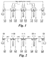
- FIG. 1 A typical prior art apparatus involving five circuit breakers is shown in figure 1.
- the circuit breakers are denoted CB1, CB2, CB3, CB4 and CB5 and are provided in series between a first end 'S' of a protected line and a second end'R'.
- Each circuit breaker is provided with two current measurement relays, one for each direction.
- the time delays for each circuit breaker, starting with that nearest the first end are T 1 , T 2 , T 3 , T 4 and T 5 were T 5 > T 4 > T 3 > T 2 > T 1 .
- time delays relate to the time which elapses after a fault has been detected at a respective circuit breaker until the breaker is opened for a fault in the direction of the first end of the line, i.e. to the left of the circuit breaker.
- the delays are (starting with the circuit breaker nearest the second end of the line) T 1 ', T 2 ', T 3 ', T 4 ' and T 5 ' where T 5 ' > T 4 ' > T 3 ' > T 2 ' > T 1 '.
- Each circuit breaker therefore has two time delays associated with the breaker. With the exception of the central breaker CB3, these will be different valued.
- circuit breakers nearest an end of the line open after a shorter delay for current flowing from the direction of the near end.
- a problem with the prior art time grading technique arises where line lengths are long and a high number of circuit breakers are provided. In such a case, the some of the time delay may be unacceptably high. Also, the time delays are fixed in value once the apparatus is installed.
- a fault protection apparatus for use in a time graded fault protection scheme
- a circuit breaker means having a normally closed trip contact provided in a line
- current measurement means adapted to produce an output signal indicative of the current in the line at the circuit breaker means
- fault signal processing means adapted to process the output signal from the current measurement means to detect an initial fault on the line at a first instance
- the fault signal processing means is further adapted to process the output of the current measurement means after the initial fault has been detected and to produce an accelerated opening signal in the event that the output signal meets a predetermined criteria
- control means are adapted to open the circuit breaker trip contact in response to said accelerated opening signal.
- the output signal may be adapted to meet the predetermined criteria when an event on the line indicative of the operation of a remote circuit breaker means on the line occurs and the output signal after the operation remains indicative of a fault on the line. Under these conditions on accelerated opening signal may be produced and the circuit breaker may then be opened instantly. If the output signal indicates that a remote circuit breaker has opened and the fault has been cleared from the protected portion of line, no accelerated trip signal will be generated and the circuit breaker may be kept closed.
- the current measurement means may comprise a forward and reverse current measurement means adapted to produce an output signal indicative of the current flowing in the line on either side of the fault protection apparatus. This allows the apparatus to decide where the fault is on the line. Two fault signal processing means may then be provided, one for each direction. A directional response to faults can then be achieved.
- the fault signal processing means may be adapted to produce an accelerated opening signal if a fault condition meeting the predetermined criteria is detected by the forward current measurement means but not by the reverse opening means. If a fault is initially detected by the reverse current measurement means, a time delayed opening signal may be generated which is used by the control means to open the circuit breaker after a predetermined time delay, say 0.5 seconds.
- each fault protection apparatus comprising at least two fault protection apparatus respectively provided at a first and second end of a protected portion of the line, each fault protection apparatus comprising at least one circuit breaker means, a forward and reverse current measurement means associated with each circuit breaker means, the forward current measurement means being adapted to measure current flowing in the line from a first direction and, the reverse current measurement means being adapted to measure current flowing in the line from the second opposite direction, control means associated with each circuit breaker, each control means being adapted to open its respective circuit breaker after a first predetermined period of time in response to an initial fault detected by processing the output of the forward current measurement means associated with the breaker and fault signal processing means associated with at least one of said circuit breakers adapted to monitor the output of the reverse current measurement means so that in the event that the output from the reverse current measurement means meets a predetermined criteria after an initial fault has been detected, the control means is adapted to open the respective circuit breaker at an accelerated time.
- the fault signal processing means may be adapted to produce an accelerated opening signal which is used by the control means to open the circuit breaker.
- control means may cause the circuit breaker to open after a predetermined time period has elapsed since an initial fault is detected by the reverse current measurement means.
- the invention provides a time graded fault protection apparatus for a line in which at least one fault protection apparatus is adapted to make an accelerated opening decision for certain fault conditions which increases speed of response.
- the slower reacting fault protection apparatus (those at a far end from a fault) can only open the circuit breaker after their predetermined time delay has elapsed following initial fault detection.
- the current measurement means may, in an alternative, be replaced by a voltage signal measurement means adapted to measure the voltage on the line. This may be processed to produce a current signal.
- additional fault protection apparatus comprising one or more circuit breakers, associated control means and current measurement means provided in the line. Not all of the additional circuit breakers need to be able to open at an accelerated rate.
- these additional fault protection apparatus may be adapted to monitor the output of the forward and reverse current measurement means and to open the circuit breaker after a first predetermined time delay when the output of the forward circuit measurement means indicates an initial fault on the line, and after a second time delay for faults detected by monitoring the output of the reverse current measurement means.
- the second time period which elapses is greater than the first time period.
- Those circuit breakers which are further away from the end of the line from which the current flows may have increasing time delays for that direction.
- a fault signal processing means may be associated with each respective circuit breaker. This may be adapted to produce an output signal indicative of an initial fault by processing the output from the current measurement means.
- the predetermined criteria used by the fault signal processing means to make the accelerated opening decision may be satisfied if the current measured after the initial detection of a fault indicates that a remote circuit breaker on the line in the direction of the measured fault has opened and the fault has not been cleared from the protected portion of line.
- the fault signal processing means may therefore be adapted to detect the operation of another circuit breaker on a portion of line in the direction of the detected fault by processing the output of the current measurement means .
- the current measurement means may be adapted to produce three output sub-signals.
- Each signal may be associated with a respective phase of the three phase supply.
- the output sub-signals may be continuous or discontinuous, i.e. a sequence of measured values over time.
- the output signals may be indicative of the current and/or voltage on the line. They may be digital or analogue.
- the fault signal processing means may be adapted to produce an accelerated trip signal by combining values of the output signals obtained substantially at the instant that the initial fault is detected with values of the output signals obtained after the initial fault is detected.
- the circuit breaker means may comprise a forward circuit breaker and a reverse circuit breaker associated with the forward and reverse current measurement means respectively. Alternatively, it may comprise a single circuit breaker.
- the forward and reverse circuit breaker may be located on either side of a load on the line to protect the load. This enables a load to be isolated from a fault regardless of which side of the line it occurs.
- the fault signal processing means is adapted to detect changes in the output signals over time after an initial fault in order to sense the operation of another circuit breaker on the line in the direction of the fault.
- the fault signal processing means may be adapted to produce an initial fault signal in the event that the output signals indicate an unbalanced fault current condition on the line.
- the three-phase system may be represented as the sum of three phase components; a positive sequence having the same phase rotation as the original system, a negative sequence having the opposite phase rotation, and a zero sequence having no phase rotation.
- a system is said to be unbalanced when the three currents and/or voltages signals are not of equal amplitude and/or the phase differences between successive signals are unequal.
- An unbalanced fault current condition may therefore be detected by providing means adapted to monitor the negative and zero sequence quantities in the output signals.
- faults which are symmetrical may be detected by monitoring changes in the positive sequence quantity.
- Changes in the zero and/or positive and/or negative sequence quantities after the initial fault is detected can be used to detect operation of the remote circuit breaker.
- a combination of the negative, zero and/or positive sequence values before and after opening of the second circuit breaker is detected can be used to determine the location of a fault of the line. For instance, this can be used to decide if the fault is on the portion of line between the first and second circuit breakers.
- the fault signal processing means may be adapted to calculate the RMS (root mean square) values of one or more of the sequence quantities in a first step of processing the sequences to produce the initial fault signal.
- the processing means may calculate one or more ratio signals from the measured sequence values.
- the value of the ratio signals can be used as an indication of a fault condition. For example, if a ratio exceeds a predetermined threshold, a fault can be assumed to have occurred.
- a first ratio may comprise the change in the zero and negative sequence quantities. This ratio may, for example, change either on transition from non-fault to a fault condition or upon closure of a remote circuit breaker.
- a second ratio may comprise the change in the positive sequence quantity during the time period following initial fault detection. This can provide an indication of the presence of the symmetrical fault.
- the first ratio signal may be chosen so as to have a zero value under no fault or symmetrical fault condition as there will be no negative or zero sequence quantities.
- the first ratio will increase from zero if a unsymmetrical fault is detected. This increase can trigger the initial fault signal. If, subsequently, the ratio returns to zero, the fault has either cleared (transistent fault) or a remote breaker has opened to isolate the fault.
- the second ratio will increase from zero or will return to zero if the fault is cleared by the remote breaker.
- the output signals can be processed in either ways to indicate the presence of a fault and the operation of a remote breaker.
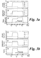
- FIG. 2 An embodiment of the present invention is shown in figure 2 of the accompanying drawings.
- the circuit breakers divide the power line into four sections named line 1, line 2, line 3 and line 4 respectively.
- Each fault protection apparatus comprises a forward direction circuit breaker CBF and a reverse direction circuit breaker CBR.
- the forward circuit breakers are adapted to open in response to currents flowing from the right in the figure 2.
- a directional current measurement device R is associated with each circuit breaker.
- the fault protection apparatus are divided into two groups.
- the first group consists of conventional time graded circuit breakers which open after either a first or a second predetermined time period as in the prior art.
- the second group consists of circuit breakers which can be opened at an accelerated rate dependent upon fault condition in response to an accelerated fault signal. Circuit breakers on the second group are shown by the use of an underscore in the figure. It can be seen that the second group consists of those circuit breakers which would have the longest default time delay in a conventional time graded scheme and which therefore benefit most from acceleration operation.
- a fault occurring on section line 1 can be considered, for example at point 'F1'.
- Each fault protection apparatus comprises a forward and reverse circuit breaker and a forward and reverse current measurement means, referred to hereinafter as relays. Only relays R1F , R1R, R2R, R3R and R4R will detect the fault since the fault is in the forward direction for these current measurement means.
- the conventional relays R1R and R2R will operate after their predetermined fixed time periods.
- the accelerated circuit breakers and associated current measurement means R1F, R3R and R4R will monitor the current to determine if it is appropriate to accelerate their opening before their predetermined fixed time periods have elapsed.
- a fault signal processing means is provided for each circuit breaker. This processes the output of the current measurement means to determine if the fault is on the section of line associated with that circuit breaker by monitoring the operation of a circuit breaker at or beyond the other side of the protected section line. If a fault is detected on the portion of line protected by the circuit breaker, and the fault remains when the other (remote) circuit breaker has opened, the fault signal processing means will instruct the control means to trip its associated circuit breaker. If the fault has cleared, the circuit breaker will remain closed.
- the process used by the fault detection circuit to detect the type of fault and its location is outlined hereinafter.
- the circuit breaker R1R With the fault of LINE 1, the circuit breaker R1R which has the fastest opening time will operate first to open its breaker. After it has opened, the fault is isolated from the sections LINE 2, LINE 3 and LINE 4.
- the relays R2R, R3R and R4R operate under a normal time grading scheme and so are restrained from opening. However, even though R1R opens one end of the line 1 portion. It does not clear the fault on the line section line 1.
- the circuit breaker R1F detects the opening of R1R and the persistence of the fault currents and so decides that the fault is on the section LINE 1 and opens its associated circuit breaker at an accelerated time. This process can be performed by comparing the output signal from the current measurement means to one or more predetermined criteria.
- the current measurement means produces a directional indication of the current and/or voltage on each phase.
- the remote circuit breaker at one end of the line section opens and the currents on the section remain unbalanced, accelerated opening can be initiated as the fault has not been cleared.
- the positive, negative and zero sequence quantities can be derived through a real-time processing algorithm.
- the Root-Mean-Square (known as RMS) values of these sequence quantities are then computed and the levels of which are compared and used to determine the system condition.
- the changes in these quantities are used to identify the operation of remote circuit breaker(s).
- S A , S B and S C are three phase power frequency voltages or currents; S 1 , S 2 and S 0 are positive, negative and zero sequence quantities.
- Equation (5) The way to speed up calculation is to reduce the required samples, that is to reduce the power of the 'e' in equation (2).
- Equation (5) The mathematical relationship of Equation (5) can be utilized :
- Equ.(9) only requires one sample delay to compute the positive and negative sequence quantities, therefore significantly increase the speed of the computation.
- Two ratio signals can be used to detect whether a system is in a balanced operation or not. Firstly, the change in the zero and negative sequence quantities with respect to the change of the positive sequence quantity is used as the main criterion to detect whether the system is in a balanced operation condition or not.
- the signal R 1 will be of zero value under no fault or symmetrical fault condition since there is no presence of negative and zero sequence quantities, and will be increased to a level well above zero if an unsymmetrical fault present on the system.
- the signal R 2 Under the symmetrical fault condition, the signal R 2 will increase to a level and return to a value around zero after the clearance of the fault from the system.
- the theoretical values for the signal R 1 will be '1' for phase to phase fault and '2' for phase to earth fault with remote circuit breaker open.
- the level of signal R 2 will be well above '1' depending on the pre- and post fault system condition.
- a preset threshold above zero level (say between 0.2 and 0.4) can be used to determine the system fault condition by examining whether the one of the two ratio signals R 1 and R 2 has exceeded it or not.
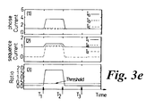
- Fig.3 shows the responses of the scheme to an 'a' phase to earth fault on line section LINE 1 as shown in Figure 2.
- the relays R1F , R1R, R2R, R3R and R4R will detect as a forward direction fault to the location where these relays are installed and the responses of which are given in Figures 3a, 3b, 3c, 3d and 3e respectively.
- the faulted phase current As shown in Figures 3a-e(1).
- the negative and zero sequence current signals also increase significantly as shown in Figures 3a-e(2), and subsequently the ratio signal as given in Equ.(11) increases to a level well above the present threshold as shown in Figures 3a-e(3).
- the relay R1R which has the fastest operating time setting will make a trip decision at 0.1 second and subsequently the circuit breaker B1R opens at the time T 2 .
- the line sections LINE 2, LINE 3 and LINE 4 are isolated from the fault.
- the measured currents return back to a balanced operation condition as shown in Figures 3c-e(1) and subsequently the negative and zero sequence currents as shown in Figures 3c-e(2) and the ratio signals as shown in Figures 3c-e(3) drop back to zero.
- the circuit breakers associated with the relays R2R, R3R and R4R restrain from operation. It should be mentioned here that the levels of the current signals may return to levels slightly different from their pre-fault values due to the change in the circuit condition after the opening of the circuit breaker B1R.
- the line section LINE 1 After the opening of the circuit breaker B1R, the line section LINE 1 becomes open circuit at one end, the phase, sequence current and ratio signals drop to zero at relay R1R location as shown in Figure 3b. Although the currents of the unfaulted phases 'b' and 'c' also drop to zero at relay R1F location as shown in Figure 3a(1), the phase 'a' to earth fault is not cleared from the line section LINE 1, the ratio signal is kept at a level of '2' as shown in Fig.3a(3), which is the theoretic level for this single phase to earth fault condition. As a result, the relay R1F detects the opening of the circuit breaker B1R and makes a trip decision and open the associated circuit breaker B1F at the time T 3 . As a result, the operating time of the circuit breaker associated with relay R1F has been significantly reduced our prior art systems.
- the time delay from the fault inception at time T 1 to the opening of the circuit breaker B1F at time T 3 mainly consists of 2 time periods, the t12 and t23.
- the first time period t12 consists of the time period from the fault inception to the opening of the circuit breaker B1R. This time period is mainly dependent on the fixed time setting of the relay since the opening of the circuit breaker only takes a few power frequency cycles. In this fault condition, a 0.1 second delay is set for the relay R1R to operate.
- the second time period t23 consists of the time taken for the apparatus R1F to identify the operation of breaker B1R which can be accomplished within half to one power frequency cycles plus the response time of the circuit breaker B1F which is approximately 2 to 4 cycles depending on the circuit breaker used. As a result, the entire operation can be implemented within 0.2 to 0.3 seconds from the fault inception. In the conventional scheme as shown in Figure 1, however, the relay at the location of R1F will not even trip until its predetermined delay time which could be for greater.
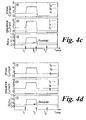
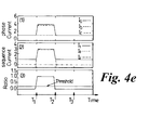
- Fig.4 show the responses of the scheme to an 'a'-'b' phase to phase fault on the line section LINE 2.
- the relays R1F , R2F, R2R, R3R and R4R detect a forward direction fault and their responses are shown in Figure 4a-e respectively.
- the circuit breaker associated with relay R2R has the fastest time setting of 0.5 second and so operates first. This subsequently opens the circuit breaker at B2R at time T 2 . Afterwards, the fault is isolated from the line section LINE 3 and LINE 4 and the circuit breakers associated with relays R3R and R4R restrain from operation.
- the relay R1F detects no opening of the circuit breaker B1R due to the presence of the unfaulted phase 'c' current as shown in Fig.4a(1). As a result, the circuit breaker associated with relay R1F is prohibited from the accelerated operation.
- the relay R2F detects the operation of the circuit breaker at R2R through the ratio signal is at a level of '1' for the phase to phase fault condition and the unfaulted phase 'c' currents drops to zero, subsequently makes a trip decision and opens its associated circuit breaker at B2F at time T 2 .
- the faulted section LINE 2 is tripped at both ends.
- the line section LINE 1 is isolated from the fault and the circuit breaker associated with relay R1F restrain from operation.
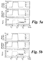
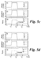
- Fig.5 shows the responses of the scheme to a three phase resistive earth fault on the line section LINE 4. Since this is a symmetric fault, there is neither zero nor negative sequence component presents as shown in Figures 5a-e(2), and as a result, the signal ratio R 1 as given in Equation(11) remains unchanged for the entire period as shown in Figures 5a-e(3). In this situation, as shown in Figures 5a-e(3), the relays rely on the signal R 2 as given in Equation(12) for decision making.
- the relays R1F , R2F , R3F, R4F and R4R detect this forward fault condition and the relay circuit breaker at R4F with the fastest time setting will trip first at time of 0.1 second and subsequently open its associate breaker B4F at time T 2 .
- the opening of the circuit breaker at B4F will isolate the line sections LINE 1, LINE 2 and LINE 3 from the fault and restrain the circuit breakers associated with relays R1F , R2F and R3F from operation.
- the relay R4R detects the operation of the circuit breaker B4F through the change in the ratio signal R 2 at time T 2 , makes an accelerated tripping decision and opens its associated circuit breaker B4R at time T 3 and the faulted line section is isolated from both ends.
- the invention provides a time graded protection apparatus in which accelerated opening of one or more of the circuit breakers can be achieved in the event that the fault condition meets predetermined criteria.
- these criteria may include the fault being on the section of line associated with the circuit breaker.
- the predetermined fault criteria may only be met once a remote circuit breaker has closed and the fault is not cleared from the protected portion of line.
- the closure of a remote breaker can be detected from changes in the line current after initial fault detection.
- the clearance at the fault can also be detected from measurements of the line signal.
Landscapes
- Emergency Protection Circuit Devices (AREA)
- Protection Of Static Devices (AREA)
- Power Steering Mechanism (AREA)
- Train Traffic Observation, Control, And Security (AREA)
Applications Claiming Priority (2)
| Application Number | Priority Date | Filing Date | Title |
|---|---|---|---|
| GB9820140A GB2341737B (en) | 1998-09-17 | 1998-09-17 | Fault protection apparatus |
| GB9820140 | 1998-09-17 |
Publications (3)
| Publication Number | Publication Date |
|---|---|
| EP0987807A2 true EP0987807A2 (fr) | 2000-03-22 |
| EP0987807A3 EP0987807A3 (fr) | 2002-01-23 |
| EP0987807B1 EP0987807B1 (fr) | 2011-03-23 |
Family
ID=10838934
Family Applications (1)
| Application Number | Title | Priority Date | Filing Date |
|---|---|---|---|
| EP99307349A Expired - Lifetime EP0987807B1 (fr) | 1998-09-17 | 1999-09-16 | Appareil de protection contre des defauts |
Country Status (7)
| Country | Link |
|---|---|
| US (1) | US6373670B1 (fr) |
| EP (1) | EP0987807B1 (fr) |
| CN (1) | CN100388586C (fr) |
| AT (1) | ATE503293T1 (fr) |
| CA (1) | CA2282624A1 (fr) |
| DE (1) | DE69943293D1 (fr) |
| GB (1) | GB2341737B (fr) |
Cited By (2)
| Publication number | Priority date | Publication date | Assignee | Title |
|---|---|---|---|---|
| WO2002091541A1 (fr) * | 2001-05-03 | 2002-11-14 | Alstom | Protection de lignes d'energie electrique |
| EP1361638A3 (fr) * | 2002-05-07 | 2011-07-20 | Areva T&D Sas | Protection de lignes d'alimentation améliorée |
Families Citing this family (14)
| Publication number | Priority date | Publication date | Assignee | Title |
|---|---|---|---|---|
| US6469629B1 (en) * | 1999-02-12 | 2002-10-22 | General Electric Company | Distributed logic in multiple protective relays |
| CN100399660C (zh) * | 2002-02-18 | 2008-07-02 | 株式会社高岳制作所 | 使用光电流传感器的保护继电装置 |
| EP1347482B1 (fr) * | 2002-03-15 | 2006-10-04 | ABB Schweiz AG | Réseau de distribution du courant |
| FR2870350B1 (fr) * | 2004-05-13 | 2006-07-14 | Schneider Electric Ind Sas | Dispositif de mesure d'un courant electrique, capteur de courant, declencheur electrique et dispositif de coupure comportant un tel dispositif de mesure |
| US8908335B2 (en) * | 2004-09-30 | 2014-12-09 | Rockwell Automation Technologies, Inc. | Arc extinguishing stab housing and method |
| US20060238936A1 (en) * | 2005-04-25 | 2006-10-26 | Blanchard Richard A | Apparatus and method for transient blocking employing relays |
| US20060250736A1 (en) * | 2005-05-06 | 2006-11-09 | Harris Richard A | Transient blocking apparatus with electrostatic discharge protection |
| FI118492B (fi) * | 2005-05-17 | 2007-11-30 | Abb Oy | Järjestelmä ja menetelmä maasulkuvian sijainnin määrittämiseksi |
| CN100362356C (zh) * | 2005-07-06 | 2008-01-16 | 李迪琪 | 故障继电器注电测试器及测试方法 |
| CN1299412C (zh) * | 2005-11-18 | 2007-02-07 | 北京交通大学 | 利用同侧电流流向变化实现方向保护的方法 |
| EP1939638B1 (fr) * | 2006-12-29 | 2011-06-15 | ABB Technology AG | Système et procédé de localisation d'un défaut phase-terre |
| DE102007008191B4 (de) * | 2007-02-09 | 2009-02-05 | Drewag - Stadtwerke Dresden Gmbh | Verfahren und Datenverarbeitungssystem zur Ermittlung der Anregebedingungen eines ortsfernen Reserveschutzsystems für Mittel- und Hochspannungsleitungen |
| US8717721B2 (en) * | 2011-08-25 | 2014-05-06 | Southern States, Llc | High impedance fault isolation system |
| CN103730882B (zh) * | 2013-12-24 | 2014-12-10 | 西安交通大学 | 一种自适应分散式电源接入的电流保护系统及方法 |
Citations (2)
| Publication number | Priority date | Publication date | Assignee | Title |
|---|---|---|---|---|
| US3379933A (en) | 1964-01-01 | 1968-04-23 | English Electric Co Ltd | Electrical protective relays |
| DD240808A1 (de) | 1985-09-05 | 1986-11-12 | Inst Prueffeld Elekt | Verfahren zum schutz von leitungen und anlagen in elektro- energieverteilungssystemen |
Family Cites Families (10)
| Publication number | Priority date | Publication date | Assignee | Title |
|---|---|---|---|---|
| CH503403A (de) * | 1969-11-26 | 1971-02-15 | Sprecher & Schuh Ag | Ueberstromschutzeinrichtung an einem elektrischen Netz, mit gestaffelten Auslösezeiten von deren Schutzrelais |
| CH583467A5 (fr) * | 1974-11-22 | 1976-12-31 | Sprecher & Schuh Ag | |
| GB2018063A (en) * | 1978-04-04 | 1979-10-10 | British Leyland Cars Ltd | A circuit breaker |
| NL176724C (nl) * | 1979-06-11 | 1985-05-17 | Hazemeijer Bv | Beveiligingsinrichting voor het selektief afschakelen van netgedeelten van een elektrisch energieverdeelnet, alsmede een energieverdeelnet voorzien van meerdere selectieve beveiligingsinrichtingen. |
| US4528611A (en) * | 1983-02-22 | 1985-07-09 | Westinghouse Electric Corp. | Relay for pilot protection of electrical power lines |
| US4484245A (en) * | 1983-06-17 | 1984-11-20 | Westinghouse Electric Corp. | Directional comparison blocking protective relay system |
| US4674002A (en) * | 1986-04-08 | 1987-06-16 | Westinghouse Electric Corp. | Directional comparison blocking system |
| US4725914A (en) * | 1986-12-16 | 1988-02-16 | Westinghouse Electric Corp. | Protective relay system for performing selective-pole trip determination |
| US4896241A (en) * | 1989-02-28 | 1990-01-23 | Westinghouse Electric Corp. | Directional comparison blocking protective relay system |
| US5838525A (en) * | 1997-04-15 | 1998-11-17 | Abb Power T&D Company, Inc. | High speed single-pole trip logic for use in protective relaying |
-
1998
- 1998-09-17 GB GB9820140A patent/GB2341737B/en not_active Expired - Fee Related
-
1999
- 1999-09-16 CA CA002282624A patent/CA2282624A1/fr not_active Abandoned
- 1999-09-16 AT AT99307349T patent/ATE503293T1/de not_active IP Right Cessation
- 1999-09-16 US US09/397,545 patent/US6373670B1/en not_active Expired - Fee Related
- 1999-09-16 DE DE69943293T patent/DE69943293D1/de not_active Expired - Lifetime
- 1999-09-16 EP EP99307349A patent/EP0987807B1/fr not_active Expired - Lifetime
- 1999-09-17 CN CNB991224760A patent/CN100388586C/zh not_active Expired - Fee Related
Patent Citations (2)
| Publication number | Priority date | Publication date | Assignee | Title |
|---|---|---|---|---|
| US3379933A (en) | 1964-01-01 | 1968-04-23 | English Electric Co Ltd | Electrical protective relays |
| DD240808A1 (de) | 1985-09-05 | 1986-11-12 | Inst Prueffeld Elekt | Verfahren zum schutz von leitungen und anlagen in elektro- energieverteilungssystemen |
Cited By (2)
| Publication number | Priority date | Publication date | Assignee | Title |
|---|---|---|---|---|
| WO2002091541A1 (fr) * | 2001-05-03 | 2002-11-14 | Alstom | Protection de lignes d'energie electrique |
| EP1361638A3 (fr) * | 2002-05-07 | 2011-07-20 | Areva T&D Sas | Protection de lignes d'alimentation améliorée |
Also Published As
| Publication number | Publication date |
|---|---|
| CA2282624A1 (fr) | 2000-03-17 |
| GB9820140D0 (en) | 1998-11-11 |
| CN1257335A (zh) | 2000-06-21 |
| DE69943293D1 (de) | 2011-05-05 |
| ATE503293T1 (de) | 2011-04-15 |
| US6373670B1 (en) | 2002-04-16 |
| EP0987807A3 (fr) | 2002-01-23 |
| GB2341737A (en) | 2000-03-22 |
| EP0987807B1 (fr) | 2011-03-23 |
| CN100388586C (zh) | 2008-05-14 |
| GB2341737B (en) | 2003-03-05 |
Similar Documents
| Publication | Publication Date | Title |
|---|---|---|
| EP1011185B1 (fr) | Système de protection contre des défauts amélioré | |
| EP0987807B1 (fr) | Appareil de protection contre des defauts | |
| US6573726B1 (en) | Sensitive ground fault detection system for use in compensated electric power distribution networks | |
| US6914762B2 (en) | Protection of electrical power lines | |
| US7196884B2 (en) | Apparatus and method for detecting the loss of a current transformer connection coupling a current differential relay to an element of a power system | |
| US6525543B1 (en) | Fault type selection system for identifying faults in an electric power system | |
| KR20080063144A (ko) | 릴레이 디바이스 동작 방법 및 컴퓨터 프로그램 제품 | |
| EP0316204B1 (fr) | Relais de protection | |
| US7102866B2 (en) | Power line protection | |
| EP1313194A2 (fr) | Protection de lignes d'énergie à double circuit | |
| US5838525A (en) | High speed single-pole trip logic for use in protective relaying | |
| US5808845A (en) | System for preventing sympathetic tripping in a power system | |
| JP2004080839A (ja) | 地絡方向継電器および地絡方向継電装置 | |
| CA2203166A1 (fr) | Comparateur numerique | |
| EP2328249B1 (fr) | Procédé de réenclenchement pour ligne de transport d'énergie électrique | |
| RU2355090C1 (ru) | Способ быстродействующей максимальной токовой защиты электрических цепей (варианты) | |
| Calero et al. | Adaptive phase and ground quadrilateral distance elements | |
| Bo | Adaptive non-communication protection for power lines BO scheme 3-The accelerated operation approach | |
| Khorashadi-Zadeh et al. | A novel PMU-based transmission line protection scheme design | |
| US12153079B2 (en) | Identifying conductor breaks by detecting series arcing | |
| Gan et al. | A new protection scheme for high impedance fault using adaptive trip and reclosure technique | |
| Izykowski et al. | DISTANCE PROTECTION OF DOUBLEœCIRCUIT TRANSMISSION LINES WITH COMPENSATION FOR THE REACTANCE EFFECT UNDER STANDARD AVAILABILITY OF MEASUREMENTS | |
| Bollen et al. | Travelling-wave-based protection: directional, differential or distance? | |
| Suwannakarn et al. | Performance analysis of zone 3 relay with state diagram under transient condition |
Legal Events
| Date | Code | Title | Description |
|---|---|---|---|
| PUAI | Public reference made under article 153(3) epc to a published international application that has entered the european phase |
Free format text: ORIGINAL CODE: 0009012 |
|
| AK | Designated contracting states |
Kind code of ref document: A2 Designated state(s): AT BE CH CY DE DK ES FI FR GB GR IE IT LI LU MC NL PT SE |
|
| AX | Request for extension of the european patent |
Free format text: AL;LT;LV;MK;RO;SI |
|
| PUAL | Search report despatched |
Free format text: ORIGINAL CODE: 0009013 |
|
| AK | Designated contracting states |
Kind code of ref document: A3 Designated state(s): AT BE CH CY DE DK ES FI FR GB GR IE IT LI LU MC NL PT SE |
|
| AX | Request for extension of the european patent |
Free format text: AL;LT;LV;MK;RO;SI |
|
| 17P | Request for examination filed |
Effective date: 20020524 |
|
| AKX | Designation fees paid |
Free format text: AT BE CH CY DE DK ES FI FR GB GR IE IT LI LU MC NL PT SE |
|
| RAP1 | Party data changed (applicant data changed or rights of an application transferred) |
Owner name: ALSTOM UK |
|
| RAP1 | Party data changed (applicant data changed or rights of an application transferred) |
Owner name: AREVA T&D UK LTD. |
|
| 17Q | First examination report despatched |
Effective date: 20071213 |
|
| GRAP | Despatch of communication of intention to grant a patent |
Free format text: ORIGINAL CODE: EPIDOSNIGR1 |
|
| GRAS | Grant fee paid |
Free format text: ORIGINAL CODE: EPIDOSNIGR3 |
|
| GRAA | (expected) grant |
Free format text: ORIGINAL CODE: 0009210 |
|
| AK | Designated contracting states |
Kind code of ref document: B1 Designated state(s): AT BE CH CY DE DK ES FI FR GB GR IE IT LI LU MC NL PT SE |
|
| REG | Reference to a national code |
Ref country code: GB Ref legal event code: FG4D |
|
| REG | Reference to a national code |
Ref country code: CH Ref legal event code: EP |
|
| REG | Reference to a national code |
Ref country code: IE Ref legal event code: FG4D |
|
| REF | Corresponds to: |
Ref document number: 69943293 Country of ref document: DE Date of ref document: 20110505 Kind code of ref document: P |
|
| REG | Reference to a national code |
Ref country code: DE Ref legal event code: R096 Ref document number: 69943293 Country of ref document: DE Effective date: 20110505 |
|
| REG | Reference to a national code |
Ref country code: NL Ref legal event code: VDEP Effective date: 20110323 |
|
| PG25 | Lapsed in a contracting state [announced via postgrant information from national office to epo] |
Ref country code: GR Free format text: LAPSE BECAUSE OF FAILURE TO SUBMIT A TRANSLATION OF THE DESCRIPTION OR TO PAY THE FEE WITHIN THE PRESCRIBED TIME-LIMIT Effective date: 20110624 Ref country code: SE Free format text: LAPSE BECAUSE OF FAILURE TO SUBMIT A TRANSLATION OF THE DESCRIPTION OR TO PAY THE FEE WITHIN THE PRESCRIBED TIME-LIMIT Effective date: 20110323 |
|
| PG25 | Lapsed in a contracting state [announced via postgrant information from national office to epo] |
Ref country code: FI Free format text: LAPSE BECAUSE OF FAILURE TO SUBMIT A TRANSLATION OF THE DESCRIPTION OR TO PAY THE FEE WITHIN THE PRESCRIBED TIME-LIMIT Effective date: 20110323 Ref country code: AT Free format text: LAPSE BECAUSE OF FAILURE TO SUBMIT A TRANSLATION OF THE DESCRIPTION OR TO PAY THE FEE WITHIN THE PRESCRIBED TIME-LIMIT Effective date: 20110323 Ref country code: CY Free format text: LAPSE BECAUSE OF FAILURE TO SUBMIT A TRANSLATION OF THE DESCRIPTION OR TO PAY THE FEE WITHIN THE PRESCRIBED TIME-LIMIT Effective date: 20110323 |
|
| PG25 | Lapsed in a contracting state [announced via postgrant information from national office to epo] |
Ref country code: BE Free format text: LAPSE BECAUSE OF FAILURE TO SUBMIT A TRANSLATION OF THE DESCRIPTION OR TO PAY THE FEE WITHIN THE PRESCRIBED TIME-LIMIT Effective date: 20110323 |
|
| PG25 | Lapsed in a contracting state [announced via postgrant information from national office to epo] |
Ref country code: PT Free format text: LAPSE BECAUSE OF FAILURE TO SUBMIT A TRANSLATION OF THE DESCRIPTION OR TO PAY THE FEE WITHIN THE PRESCRIBED TIME-LIMIT Effective date: 20110725 |
|
| PG25 | Lapsed in a contracting state [announced via postgrant information from national office to epo] |
Ref country code: ES Free format text: LAPSE BECAUSE OF FAILURE TO SUBMIT A TRANSLATION OF THE DESCRIPTION OR TO PAY THE FEE WITHIN THE PRESCRIBED TIME-LIMIT Effective date: 20110704 |
|
| PGFP | Annual fee paid to national office [announced via postgrant information from national office to epo] |
Ref country code: FR Payment date: 20110928 Year of fee payment: 13 Ref country code: DE Payment date: 20110923 Year of fee payment: 13 |
|
| PG25 | Lapsed in a contracting state [announced via postgrant information from national office to epo] |
Ref country code: NL Free format text: LAPSE BECAUSE OF FAILURE TO SUBMIT A TRANSLATION OF THE DESCRIPTION OR TO PAY THE FEE WITHIN THE PRESCRIBED TIME-LIMIT Effective date: 20110323 |
|
| RAP2 | Party data changed (patent owner data changed or rights of a patent transferred) |
Owner name: SCHNEIDER ELECTRIC ENERGY UK LTD Owner name: AREVA T&D UK LTD. |
|
| PLBE | No opposition filed within time limit |
Free format text: ORIGINAL CODE: 0009261 |
|
| STAA | Information on the status of an ep patent application or granted ep patent |
Free format text: STATUS: NO OPPOSITION FILED WITHIN TIME LIMIT |
|
| 26N | No opposition filed |
Effective date: 20111227 |
|
| PG25 | Lapsed in a contracting state [announced via postgrant information from national office to epo] |
Ref country code: DK Free format text: LAPSE BECAUSE OF FAILURE TO SUBMIT A TRANSLATION OF THE DESCRIPTION OR TO PAY THE FEE WITHIN THE PRESCRIBED TIME-LIMIT Effective date: 20110323 |
|
| REG | Reference to a national code |
Ref country code: DE Ref legal event code: R097 Ref document number: 69943293 Country of ref document: DE Effective date: 20111227 |
|
| PG25 | Lapsed in a contracting state [announced via postgrant information from national office to epo] |
Ref country code: MC Free format text: LAPSE BECAUSE OF NON-PAYMENT OF DUE FEES Effective date: 20110930 |
|
| REG | Reference to a national code |
Ref country code: CH Ref legal event code: PL |
|
| GBPC | Gb: european patent ceased through non-payment of renewal fee |
Effective date: 20110916 |
|
| PG25 | Lapsed in a contracting state [announced via postgrant information from national office to epo] |
Ref country code: IT Free format text: LAPSE BECAUSE OF FAILURE TO SUBMIT A TRANSLATION OF THE DESCRIPTION OR TO PAY THE FEE WITHIN THE PRESCRIBED TIME-LIMIT Effective date: 20110323 |
|
| REG | Reference to a national code |
Ref country code: IE Ref legal event code: MM4A |
|
| PG25 | Lapsed in a contracting state [announced via postgrant information from national office to epo] |
Ref country code: LI Free format text: LAPSE BECAUSE OF NON-PAYMENT OF DUE FEES Effective date: 20110930 Ref country code: IE Free format text: LAPSE BECAUSE OF NON-PAYMENT OF DUE FEES Effective date: 20110916 Ref country code: CH Free format text: LAPSE BECAUSE OF NON-PAYMENT OF DUE FEES Effective date: 20110930 |
|
| PG25 | Lapsed in a contracting state [announced via postgrant information from national office to epo] |
Ref country code: GB Free format text: LAPSE BECAUSE OF NON-PAYMENT OF DUE FEES Effective date: 20110916 |
|
| PG25 | Lapsed in a contracting state [announced via postgrant information from national office to epo] |
Ref country code: LU Free format text: LAPSE BECAUSE OF NON-PAYMENT OF DUE FEES Effective date: 20110916 |
|
| REG | Reference to a national code |
Ref country code: FR Ref legal event code: ST Effective date: 20130531 |
|
| PG25 | Lapsed in a contracting state [announced via postgrant information from national office to epo] |
Ref country code: DE Free format text: LAPSE BECAUSE OF NON-PAYMENT OF DUE FEES Effective date: 20130403 |
|
| PG25 | Lapsed in a contracting state [announced via postgrant information from national office to epo] |
Ref country code: FR Free format text: LAPSE BECAUSE OF NON-PAYMENT OF DUE FEES Effective date: 20121001 |
|
| REG | Reference to a national code |
Ref country code: DE Ref legal event code: R119 Ref document number: 69943293 Country of ref document: DE Effective date: 20130403 |