EP0987813A2 - Filterungsoptimierung von übertragenen Störungen - Google Patents
Filterungsoptimierung von übertragenen Störungen Download PDFInfo
- Publication number
- EP0987813A2 EP0987813A2 EP99660138A EP99660138A EP0987813A2 EP 0987813 A2 EP0987813 A2 EP 0987813A2 EP 99660138 A EP99660138 A EP 99660138A EP 99660138 A EP99660138 A EP 99660138A EP 0987813 A2 EP0987813 A2 EP 0987813A2
- Authority
- EP
- European Patent Office
- Prior art keywords
- common mode
- current
- frequency converter
- frequency
- feeder
- Prior art date
- Legal status (The legal status is an assumption and is not a legal conclusion. Google has not performed a legal analysis and makes no representation as to the accuracy of the status listed.)
- Withdrawn
Links
- 238000001914 filtration Methods 0.000 title claims abstract description 12
- 238000005457 optimization Methods 0.000 title description 2
- 238000000034 method Methods 0.000 claims abstract description 16
- 230000008859 change Effects 0.000 claims description 8
- 239000004020 conductor Substances 0.000 claims description 6
- 230000001681 protective effect Effects 0.000 claims description 3
- 230000007423 decrease Effects 0.000 description 6
- 239000004065 semiconductor Substances 0.000 description 4
- 238000004804 winding Methods 0.000 description 4
- 239000003990 capacitor Substances 0.000 description 3
- 230000008878 coupling Effects 0.000 description 3
- 238000010168 coupling process Methods 0.000 description 3
- 238000005859 coupling reaction Methods 0.000 description 3
- 239000000696 magnetic material Substances 0.000 description 3
- 230000008901 benefit Effects 0.000 description 2
- 230000000694 effects Effects 0.000 description 2
- 230000005855 radiation Effects 0.000 description 2
- 230000007704 transition Effects 0.000 description 2
- 238000007792 addition Methods 0.000 description 1
- 230000005670 electromagnetic radiation Effects 0.000 description 1
- 238000005516 engineering process Methods 0.000 description 1
- 230000001939 inductive effect Effects 0.000 description 1
- 230000004224 protection Effects 0.000 description 1
- 229920006395 saturated elastomer Polymers 0.000 description 1
- 229910000859 α-Fe Inorganic materials 0.000 description 1
Images
Classifications
-
- H—ELECTRICITY
- H02—GENERATION; CONVERSION OR DISTRIBUTION OF ELECTRIC POWER
- H02M—APPARATUS FOR CONVERSION BETWEEN AC AND AC, BETWEEN AC AND DC, OR BETWEEN DC AND DC, AND FOR USE WITH MAINS OR SIMILAR POWER SUPPLY SYSTEMS; CONVERSION OF DC OR AC INPUT POWER INTO SURGE OUTPUT POWER; CONTROL OR REGULATION THEREOF
- H02M1/00—Details of apparatus for conversion
- H02M1/44—Circuits or arrangements for compensating for electromagnetic interference in converters or inverters
Definitions
- the present invention relates to a method and arrangement for optimizing the filtration of conducted high-frequency disturbances in a frequency converter, the frequency converter being coupled with a feeder to a supply network and having a variable switching frequency.
- a high-power device of this kind is, for instance, a frequency converter commonly used for motor controlling.
- Frequency converters convert a known constant supply frequency to a desired output frequency.
- the output frequency is generated by connecting to the output DC pulses whose width is modulated in accordance with the necessary output voltage.
- Output voltage generation of this kind is known as pulse width modulation (PWM).
- PWM pulse width modulation
- the switching frequency, at which DC pulses are connected to the output of the device is typically within the range of 1 kHz to 16 kHz.
- the transition of the high-power semiconductors from one state into another should occur as fast as possible.
- High rates of change together with high voltages and currents to be coupled inevitably produce electromagnetic disturbances, which spread in the environment both as radiation and as conducted phenomena.
- Conducted disturbances distort the supply network voltage, and conducted radio-frequency disturbances further emit electromagnetic radiation, which may interfere with other sensitive devices within the range of radiation.
- a plurality of different standards define the limits below which the electromagnetic emission from the electric devices should remain. Compliance with the standards contributes to the electromagnetic compatibility of various devices.
- RFI radio frequency interference
- filters to be coupled to feeders are commonly used. These filters typically comprise a coupling of capacitive and inductive components.
- the RFI filter inductance may comprise both phase-specific and common mode choke, but to save on costs, common mode chokes alone are often used in these filters.
- the switching frequency of the frequency converter also has an effect on the magnitude of the common mode current passing through earth capacitances.
- the common mode current tends to return to the source of disturbance, i.e.
- the switching frequency of the frequency converter is at the resonance frequency of an LC circuit formed together by the supply network earth capacitance and the supply network's inductance and the RFI filter's common mode inductance, the common mode currents tend to return to the source of disturbance via said route and not via the desired route, i.e. via the anti-interference capacitors.
- the object of the present invention is to provide a method which avoids the above-described drawbacks and enables filtration of conducted high-frequency disturbances in a more efficient manner. This is achieved with the method of the invention, which is characterized by comprising the steps of
- the method of the invention is based on optimizing the filtration by measuring the common mode current passing in the frequency converter feeder and by changing the switching frequency of the frequency converter when the common mode current exceeds the predetermined current limit.
- the invention also relates to an arrangement for optimizing the filtration of conducted high-frequency disturbances in a frequency converter, the frequency converter being coupled with a feeder to a supply network and comprising a variable switching frequency, whereby the arrangement is characterized by comprising interconnectedly
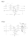
- a network filter of Figure 1 is conventionally used in accordance with prior art to limit the propagation of disturbance currents either from the network to a device or from the device back to the network.
- the disclosed network filter comprises two common mode chokes L1, L2 and capacitor couplings C1, C2, C3 and C4.
- the filter works as a low-pass filter, removing components with the highest frequencies from the passing current.
- the filter is particularly optimized to limit the propagation of the common mode current.
- the common mode current refers to current components, which are codirectional disturbance currents in all phases.
- the common mode currents most typically result from capacitive currents passing through high earth capacitances of motor cables. High-power semiconductors of the frequency converters change states quickly, whereby quick and great changes in the potential enable propagation of the current through earth capacitances. Capacitive earth currents in turn cause an undesirable common mode current in the feeders.
- the motor cables being long, the earth capacitance is quite considerable, which further causes high common mode currents. Moreover, for every motor cable length there is a switching frequency of the frequency converter, at which the common mode current is at the highest.
- a high common mode current causes saturation in the magnetic material of the common mode chokes, which in turn leads to a considerable decrease in the interference filtering capacity of the filter. In connection with the choke saturation, the filtering capacity decreases particularly dramatically at the frequencies of less than 1 MHz.
- Figure 2 shows a network filter, to which is combined a current defining means 1 for measuring the common mode current.
- the functions of the network filter are similar to those of the filter in Figure 1.
- Input phases are intended to be coupled to filter inputs U, V, W, and further from the filter output to a device, such as a frequency converter, through connectors R, S, T.
- the described network filters only exemplify a possible structure of the network filter, and it is obvious that there are several different filter types for different purposes.
- the common mode current of the frequency converter feeder is defined.
- the current defining means 1 defines the magnitude of the common mode current, and a current Icom, corresponding to the magnitude of the common mode current, passes in a signal line 2 of the means 1.
- the common mode current is defined in the phase conductors of the feeder.
- the current defining means 1 is a common mode current transformer whose primary winding consists of phase conductors passing through the transformer core 3 and a secondary winding consists of the signal line 2.
- the common mode current transformer refers to a transformer that transforms a secondary current from the common mode current of the primary winding.
- the current Icom of the signal line 2 is applied from the signal connectors I+, I- of the filter to the comparing means, where the magnitude of the current is compared with a predetermined limit value. If the signal line current exceeds the predetermined limit value, the switching frequency of the frequency converter will be changed. The switching frequency is changed until the disturbance current is below the limit value.
- a control means such as a microprocessor of the frequency converter, communicating with the comparing means, changes the switching frequency instructions of the frequency converter. When needed, the switching frequency can alternatively be changed upwards or downwards, whereby the switching frequency increases or decreases. If a change of the switching frequency in one direction does not produce a desired decrease in the common mode current, it is possible to change the direction of the switching frequency. As stated, the switching frequency has an effect on the magnitude of the common mode current, and consequently on the level of conducted high-frequency disturbances. In practice, it is necessary to optimize the switching frequency only once, when putting the device into use.
- the optimum switching frequency can be searched well before potential saturation and a decrease in filtering capacity resulting therefrom. This procedure saves considerably on filter design and costs, and moreover the filtering capacity improves. Thanks to the method, the common mode currents supplied into the network by the frequency converter are also minimized, whereby fault current protections do not unnecessarily trip the device off from the network, because the fault current definition is based on measuring the common mode current.
- the common mode disturbance current is defined directly from the input phase protective earth conductors (PE), and consequently, when using the common mode current transformer, only the protective earth conductor has to be applied through the transformer.
- PE input phase protective earth conductors
- the common mode current transformer can also be combined to the common mode choke of the network filter. In that case, a signal line has to be added as a secondary winding to the choke. This structure further saves on magnetic material, because no separate core is necessary for the current defining means.
Landscapes
- Physics & Mathematics (AREA)
- Electromagnetism (AREA)
- Engineering & Computer Science (AREA)
- Power Engineering (AREA)
- Power Conversion In General (AREA)
- Supply And Distribution Of Alternating Current (AREA)
- Dc-Dc Converters (AREA)
- Networks Using Active Elements (AREA)
- Control Of Ac Motors In General (AREA)
- Ac-Ac Conversion (AREA)
- Filters And Equalizers (AREA)
Applications Claiming Priority (2)
| Application Number | Priority Date | Filing Date | Title |
|---|---|---|---|
| FI981975A FI108761B (fi) | 1998-09-14 | 1998-09-14 | Johtuvien häiriöiden suodatuksen optimointi |
| FI981975 | 1998-09-14 |
Publications (2)
| Publication Number | Publication Date |
|---|---|
| EP0987813A2 true EP0987813A2 (de) | 2000-03-22 |
| EP0987813A3 EP0987813A3 (de) | 2000-04-19 |
Family
ID=8552482
Family Applications (1)
| Application Number | Title | Priority Date | Filing Date |
|---|---|---|---|
| EP99660138A Withdrawn EP0987813A3 (de) | 1998-09-14 | 1999-09-03 | Filterungsoptimierung von übertragenen Störungen |
Country Status (4)
| Country | Link |
|---|---|
| EP (1) | EP0987813A3 (de) |
| JP (1) | JP2000102242A (de) |
| AU (1) | AU749797B2 (de) |
| FI (1) | FI108761B (de) |
Cited By (5)
| Publication number | Priority date | Publication date | Assignee | Title |
|---|---|---|---|---|
| DE10039957A1 (de) * | 2000-08-16 | 2002-03-07 | Siemens Ag | Vorrichtung zur Grundentstörung eines Matrixumrichters |
| DE102004006553B4 (de) * | 2004-02-10 | 2006-09-14 | Siemens Ag | Umrichter |
| EP1806833A4 (de) * | 2004-10-04 | 2011-06-08 | Daikin Ind Ltd | Stromumsetzer |
| EP2947759A1 (de) * | 2014-05-21 | 2015-11-25 | Vacon Oyj | Elektrische interferenzbegrenzung |
| CN115771399A (zh) * | 2021-09-06 | 2023-03-10 | 盾安汽车热管理科技有限公司 | 高压预充装置、新能源电动车及预充电路的控制方法 |
Families Citing this family (2)
| Publication number | Priority date | Publication date | Assignee | Title |
|---|---|---|---|---|
| WO2019102937A1 (ja) * | 2017-11-22 | 2019-05-31 | 株式会社村田製作所 | ノイズフィルタ回路、及び、電源回路 |
| CN115360751B (zh) * | 2022-08-17 | 2025-06-03 | 中国舰船研究设计中心 | 一种十二相整流发电系统直流侧共模干扰频谱预测方法 |
Family Cites Families (2)
| Publication number | Priority date | Publication date | Assignee | Title |
|---|---|---|---|---|
| US5383084A (en) * | 1993-01-08 | 1995-01-17 | Leviton Manufacturing Co., Inc. | Circuit analyzing system |
| US5793196A (en) * | 1996-07-03 | 1998-08-11 | Sundstrand Corporation | Current transformer for measuring differential-mode and common-mode current |
-
1998
- 1998-09-14 FI FI981975A patent/FI108761B/fi active
-
1999
- 1999-09-03 EP EP99660138A patent/EP0987813A3/de not_active Withdrawn
- 1999-09-10 AU AU47498/99A patent/AU749797B2/en not_active Ceased
- 1999-09-13 JP JP11258984A patent/JP2000102242A/ja active Pending
Cited By (6)
| Publication number | Priority date | Publication date | Assignee | Title |
|---|---|---|---|---|
| DE10039957A1 (de) * | 2000-08-16 | 2002-03-07 | Siemens Ag | Vorrichtung zur Grundentstörung eines Matrixumrichters |
| DE102004006553B4 (de) * | 2004-02-10 | 2006-09-14 | Siemens Ag | Umrichter |
| EP1806833A4 (de) * | 2004-10-04 | 2011-06-08 | Daikin Ind Ltd | Stromumsetzer |
| US8008886B2 (en) | 2004-10-04 | 2011-08-30 | Daikin Industries, Ltd. | Power converter |
| EP2947759A1 (de) * | 2014-05-21 | 2015-11-25 | Vacon Oyj | Elektrische interferenzbegrenzung |
| CN115771399A (zh) * | 2021-09-06 | 2023-03-10 | 盾安汽车热管理科技有限公司 | 高压预充装置、新能源电动车及预充电路的控制方法 |
Also Published As
| Publication number | Publication date |
|---|---|
| AU4749899A (en) | 2000-03-23 |
| AU749797B2 (en) | 2002-07-04 |
| FI981975A0 (fi) | 1998-09-14 |
| FI981975L (fi) | 2000-03-15 |
| EP0987813A3 (de) | 2000-04-19 |
| FI108761B (fi) | 2002-03-15 |
| JP2000102242A (ja) | 2000-04-07 |
Similar Documents
| Publication | Publication Date | Title |
|---|---|---|
| US5956246A (en) | Low-noise switching power supply | |
| CN102332808B (zh) | 包括差模和共模的逆变器滤波器以及包括该逆变器滤波器的系统 | |
| US5686806A (en) | Low-pass filter and electronic speed control system for electric motors | |
| US7142440B2 (en) | Ripple-current reduction for transformers | |
| US6028405A (en) | Variable frequency drive noise attenuation circuit | |
| JP2001086734A (ja) | 電力変換システム | |
| US7256662B2 (en) | Common mode signal suppressing circuit and normal mode signal suppressing circuit | |
| CN100423418C (zh) | 电流补偿扼流圈和具有电流补偿扼流圈的电路装置 | |
| EP4315545B1 (de) | Filter zur unterdrückung der elektromagnetischen interferenz | |
| CA2017062C (en) | Switching power supply apparatus and isolating method thereof | |
| US11251693B2 (en) | Electrical filter device for filtering a common-mode interference between a current source and a load | |
| US20050275368A1 (en) | Filter network | |
| EP0987813A2 (de) | Filterungsoptimierung von übertragenen Störungen | |
| US10784678B1 (en) | Damped PI-type filter Y-type capacitance network for radiated and conducted emission | |
| CA2245803C (en) | Impedance regulator system and method | |
| CN109314460B (zh) | 电力转换装置 | |
| EP3926805A1 (de) | Verfahren und vorrichtung zur reduzierung eines rippelstroms | |
| US12266458B2 (en) | Common mode choke | |
| US6847530B2 (en) | Low output noise switched mode power supply with shieldless transformers | |
| KR20210108126A (ko) | 매트릭스 컨버터의 출력 전압을 제어하는 출력 필터를 포함한 wgb 기반 전력변환장치 및 전력변환장치 제어방법 | |
| US20070001777A1 (en) | Normal mode noise suppressing circuit | |
| US5666047A (en) | Dielectric transformer | |
| CN113243075A (zh) | 用于功率适配器的直流(dc)总线电磁干扰(emi)滤波 | |
| JP2005117218A (ja) | ノイズ抑制回路 | |
| Finlayson | Output filter considerations for pwm drives with induction motors |
Legal Events
| Date | Code | Title | Description |
|---|---|---|---|
| PUAI | Public reference made under article 153(3) epc to a published international application that has entered the european phase |
Free format text: ORIGINAL CODE: 0009012 |
|
| PUAL | Search report despatched |
Free format text: ORIGINAL CODE: 0009013 |
|
| AK | Designated contracting states |
Kind code of ref document: A2 Designated state(s): DE ES FR GB IT SE |
|
| AX | Request for extension of the european patent |
Free format text: AL;LT;LV;MK;RO;SI |
|
| AK | Designated contracting states |
Kind code of ref document: A3 Designated state(s): AT BE CH CY DE DK ES FI FR GB GR IE IT LI LU MC NL PT SE |
|
| AX | Request for extension of the european patent |
Free format text: AL;LT;LV;MK;RO;SI |
|
| 17P | Request for examination filed |
Effective date: 20000912 |
|
| AKX | Designation fees paid |
Free format text: DE ES FR GB IT SE |
|
| 17Q | First examination report despatched |
Effective date: 20030701 |
|
| STAA | Information on the status of an ep patent application or granted ep patent |
Free format text: STATUS: THE APPLICATION IS DEEMED TO BE WITHDRAWN |
|
| 18D | Application deemed to be withdrawn |
Effective date: 20031112 |