EP0987837A2 - Konzept für die Nutzlast in doppelphasengesteuerten Gruppenantennen - Google Patents
Konzept für die Nutzlast in doppelphasengesteuerten Gruppenantennen Download PDFInfo
- Publication number
- EP0987837A2 EP0987837A2 EP99117936A EP99117936A EP0987837A2 EP 0987837 A2 EP0987837 A2 EP 0987837A2 EP 99117936 A EP99117936 A EP 99117936A EP 99117936 A EP99117936 A EP 99117936A EP 0987837 A2 EP0987837 A2 EP 0987837A2
- Authority
- EP
- European Patent Office
- Prior art keywords
- phased array
- payload
- packet switch
- dual
- outputs
- Prior art date
- Legal status (The legal status is an assumption and is not a legal conclusion. Google has not performed a legal analysis and makes no representation as to the accuracy of the status listed.)
- Withdrawn
Links
Images
Classifications
-
- H—ELECTRICITY
- H04—ELECTRIC COMMUNICATION TECHNIQUE
- H04B—TRANSMISSION
- H04B7/00—Radio transmission systems, i.e. using radiation field
- H04B7/14—Relay systems
- H04B7/15—Active relay systems
- H04B7/185—Space-based or airborne stations; Stations for satellite systems
- H04B7/1851—Systems using a satellite or space-based relay
- H04B7/18515—Transmission equipment in satellites or space-based relays
Definitions
- the present invention relates to a communications satellite transmission and reception architecture that includes phased array antennas.
- the present invention relates to a satellite payload that coordinates a transmit phased array antenna, packet switch, and a receive phased array antenna.
- Satellites are a common feature of modern communications networks and have long provided communications services on a global scale.
- a communications satellite often flies in a geostationary (GSO) orbit (at approximately 35,784 km altitude with an inclination and eccentricity of zero) so that the satellite always appears in the same spot in the sky. Satellites, however, may also be placed in other orbits, including Non-geostationary orbits (NGSO).
- GSO geostationary
- NGSO Non-geostationary orbits
- a NGSO satellite typically orbits between 250 and 12000 km above the Earth. NGSO satellites orbit the Earth independently of the Earth's own rotation and therefore do not maintain a constant location in the sky. Because the orbit of a NGSO satellite periodically takes the NGSO satellite over various locations on the Earth, the NGSO satellite may be used to provide periodic communications services to those locations. A constellation of many NGSO satellites may be used to provide nearly continuous coverage to virtually all areas of the Earth.
- Teledesic LLC located in Kirkland Washington, United States, has proposed a NGSO constellation referred to as the Teledesic Network which flies 288 NGSO satellites.
- the Teledesic Network incorporates 12 orbital planes with 24 NGSO satellites per plane. Each orbital plane is approximately perpendicular to the equator and separated from adjacent orbital planes by approximately 15 degrees. The altitudes of the satellites in each orbital plane are staggered so that the satellites pass below and above one another at the North and South poles, where each orbital plane converges.
- ISL intersatellite links
- North-South links provide continuous connections between the satellites in individual orbital planes. Any first satellite in an orbital plane has a connection to a second satellite ahead of its current position and a third satellite behind its current position.
- East-West links provice a connection between the satellites in a first orbital plane and the satellites in a second orbital plane and a third orbital plane on either side of the first orbital plane (the adjacent orbital planes).
- MBAs Multi-Beam Antennas
- each MBA is selectively activated or deactivated to provide coverage for a ROI as the satellite moves from one ROI to another ROI.
- the complex configurations of MBAs require the satellite to include a complex switching network to activate and deactivate the MBAs.
- the complex switching network and additional MBAs increase the power demand on the satellite's limited power supply as well as drive up the size and weight of the satellite (making the satellite more expensive to build, transport, and launch).
- satellites have attempted to cope with the complexity of MBA design by purposefully creating payloads with sub-optimal MBA configurations using fewer MBA components. Because an MBA design providing optimal coverage for one ROI generally results in very poor coverage for the other ROIs, a compromised, sub-optimal MBA configuration is typically used.
- the sub-optimal configuration reduces the complexity of the MBA design and relieves the very poor coverage for the other ROIs by providing sub-optimal coverage for all ROIs.
- the sub-optimal configuration also reduces the amount of communications capacity available to the ROIs and thereby limits the amount of information that may be transmitted and received as the satellite moves overhead. Revenues are correspondingly reduced.
- Yet another object of the present invention is to provide a communications satellite with the ability to flexibly adjust its uplink and downlink beam coverage using phased array antennas.
- Another object of the present invention is to allow a communications satellite to route information between a receive phased array antenna and a transmit phased array antenna using a packet switch.
- the present invention provides a dual (i.e., including both transmit and receive antennas) phased array payload for use onboard a communications satellite.
- the payload includes a phased array receive antenna including numerous individual receiving elements distributed in a predetermined configuration.
- Each of the individual radiating elements has a low noise amplifier (LNA) and is selectively adjustable in phase and amplitude to achieve scanning beams for receiving information transmitted from the ground in an uplink beam.
- LNA low noise amplifier
- the payload also includes a packet switch connected to the phased array receive antenna.
- the packet switch includes a set of inputs and a set of outputs. Each input is selectively connectable to one or more outputs.
- the payload includes a phased array transmit antenna connected to the packet switch.
- the phased array transmit antenna includes numerous individual radiating elements distributed in a predetermined configuration. Each of the individual radiating elements has a power amplifier, as well as a controllable amplitude and phase excitation used to electronically steer a downlink beam produced by the radiating elements in combination.
- a payload computer is connected to the packet switch.
- the payload computer generates outputs that control the connection of the packet switch inputs to the packet switch outputs.
- the payload may further include a downconverter connected to the phased array receive antenna, an analog to digital converter connected to the downconverter, and a demodulator/decoder connected to the analog to digital converter.
- An encoder/modulator may additionally be connected to the packet switch, and an upconverter may also be connected to the encoder/modulator and the phased array transmit antenna.
- the communications satellite may additionally communicate with the ground, or with other satellites, using a beacon transmitter and receiver.
- the beacon transmitter and receiver operate under control of the payload computer to transmit and receive command, control, and status information.
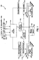
- the payload 100 includes the phased array receive antennas 102-108 ("receive antennas") connected to a low noise amplifier and next to downconverter 110.
- the downconverter 110 is in turn connected to channel recovery circuitry 112 including an Analog to Digital Converter (ADC), a channelizer, and demodulators/decoders.
- a packet switch 114 is included and connected to the channel recovery circuitry 112 as well as an encoder/modulator 116.
- An upconverter 118 is connected between the encoder/modulator 116 and the phased array transmit antennas 120-126 ("transmit antennas").
- a beacon 128 and associated beacon control 130 are also included.
- a payload computer 132 controls the operation of the payload 100, and in particular, is connected to the packet switch 114 and the beacon control 128.
- a frequency generator 134 is provided to produce the frequencies required by the downconverter 110 and the upconverter 118.
- the payload may also include an ISL North transmitter and receiver pair 136 and an ISL South transmitter and receiver pair 138 as well as an ISL East transmitter and receiver pair 140 and an ISL West transmitter and receiver pair 142.
- the phased array receive antennas 102-108 replace the complex MBA antenna discussed above and receive RF energy forming uplink beams.
- the uplink beams may, for example, contain RF energy at approximately 28.6 - 29.1 GHz and contain numerous individual channels.
- the transmit antennas may be used to form downlink beams containing one or more channels, for example, in the 18.8 - 19.3 GHz band.
- Each phased array antenna is composed of a group of individual radiators which are distributed in a predetermined configuration, for example a linear or two-dimensional spatial configuration.
- the radiators may be implemented, for example, as dipoles, slots, open-ended waveguides, spirals, microstrip or patch elements.
- each radiator is individually controlled to form a radiated beam of any desired shape.
- the direction of the beam in space is controlled electronically by adjusting the phase of the excitation signals at the individual radiators.
- the phased array antenna may steer a transmitted beam while the phased array antenna remains fixed in space. In other words, no mechanical motion is required to accomplish beam steering.
- each radiator may be monitored or scanned in turn to determine the RF energy incident upon the radiator to recover a transmitted RF signal.
- Phased array antennas suitable for use with the present invention are available from TRW, Inc., Redondo Beach CA 90278. Additional information on phased array antennas may be found in the Antenna Engineering Handbook (Richard C. Johnson, ed.) 20-1 - 20-67 (1993). Pages 20-1 - 20-67 of the Antenna Engineering Handbook are incorporated herein by reference in their entirety.
- No particular number of receive antennas or transmit antennas is required; one or more of each may be used. In certain preferred embodiments, however, power dissipation requirements may suggest a certain structure for the transmit antennas. For example, current technology allows approximately 30% of DC power applied to the transmit antennas to result in useful RF power. Thus, 70% of the DC power generally turns into heat. As a result, several smaller transmit antennas 120-126 that generally point NE, NW, SE, and SW (and that dissipate heat more readily) may be used instead of one large transmit antenna.
- the receive antennas 102-108 are connected to the low noise amplifier and downconverter 110.
- the downconverter 110 uses a mixer to shift the frequency of the received RF energy to an intermediate frequency that may be operated on by the channel recovery circuitry 112.
- the frequency generator 134 is responsible for generating the frequencies used by the downconverter 110 and may use Voltage Controlled Oscillators (VCOs), Numerically Controlled Oscillators (NCOs) and the like.
- VCOs Voltage Controlled Oscillators
- NCOs Numerically Controlled Oscillators
- the channel recovery circuitry 112 includes an analog-to-digital converter (ADC) to convert the received uplink beam to digital samples.
- a channelization function follows which separates out the individual channels in the uplink beam and routes the channels to demodulators.
- the demodulators/decoders remove modulation and encoding applied to the uplink beam, for example Quadrature Phase Shift Keying (QPSK) or 16 level Quadrature Amplitude Modulation (16-QAM).
- QPSK Quadrature Phase Shift Keying
- 16-QAM 16 level Quadrature Amplitude Modulation
- the demodulated and decoded digital bits recovered by the channel recovery circuitry 112 therefore represent those packets.
- the packets typically include header information and data information.
- the header information may include, for example, synchronization information, error correcting information, and routing information that describes the source and destination for the data information.
- the payload computer 132 may use the routing information in part to control the packet switch 114. Packets may also be routed to or from the payload computer 132 to facilitate communications resource control.
- the packet switch 114 generally includes N inputs and M outputs and is able to connect the N inputs to any of the M outputs.
- the N inputs may be assigned to each uplink or intersatellite link (ISL) channel and the M outputs may be assigned to each downlink or intersatellite link (ISL) channel.
- the routing information may indicate that a particular packet recovered from the first uplink channel is destined for a particular region of interest (ROI).
- the payload computer 132 may then determine which downlink beam covers that ROI and adjust the packet switch 114 to connect the input used for the packet to the output used to generate the downlink beam covering the ROI.
- the packet switch also supports functions such as multicast (in which a single packet is forwarded to more than one downlink beam or ISL) and broadcast (in which a single packet is forwarded to all downlink beams and ISLs).
- functions such as multicast (in which a single packet is forwarded to more than one downlink beam or ISL) and broadcast (in which a single packet is forwarded to all downlink beams and ISLs).
- a packet switch suitable for use in the present invention is available from TRW, Inc., Redondo Beach CA, 90278.
- the outputs of the packet switch 114 are used to generate downlink or intersatellite links (ISL) beams.
- the first step in generating downlink beams is performed by the encoder/modulator 116 which takes digital bits from the packet switch 114 and generates symbols that may simultaneously carry multiple bits. Modulation added by the modulator 116 may include, for example, QPSK (two bits per symbol) or 8-PSK (three bits per symbol).
- the upconverter 118 shifts the symbols produced by the modulator 116 up in frequency for transmission, typically using a mixer. As an example, the upconverter 118 may use an approximately 19 GHz frequency (generated by the frequency generator 134) to generate downlink beams in the 18.8 - 19.3 GHz range.
- the downlink beams are applied to the transmit antennas 120-126, whose individual radiating elements are controlled by the payload computer 132 for electronic steering.
- the payload 100 may optionally include optical or radio frequency (RF) intersatellite links 136-142.
- RF radio frequency
- an ISL North transmitter and receiver 136 and an ISL South transmitter and receiver 138 may be provided to establish communications between satellites in the same orbital plane.
- an ISL East transmitter and receiver 140 and an ISL West transmitter and receiver 142 may be provided to establish communications between satellites in adjacent orbital planes.
- the North, South, East, and West links may be implemented with laser optics or RF packages and may be used to interconnect the communications satellites in a network. Worldwide routing of packets may then flow through the payload 100, either to additional communications satellites over the intersatellite links 136-142, or to and from the ground using the receiver antenna 102-108 and the transmitter antennas 120-126.
- the payload 100 may include a beacon 128 and associated beacon control 130.
- the beacon 128 includes a transmitter and receiver that operate on RF frequencies to transmit and receive information to and from the ground.
- the beacon control 130 receives information to transmit from the payload computer 132 and forwards to the payload computer 132 information received by the beacon 128.
- the beacon control 130 may also include hardware for modulation, demodulation, upconversion, downconversion, and analog to digital conversion.
- the beacon provides a dedicated control channel between the payload 100 and the ground (although the beacon could conceivably be pointed at another satellite as well).
- the control channel may be used to carry command, control, and status information regarding the frequencies in use by the transmit antennas 120-126 and the receive antennas 102-108, the present amount of bandwidth available at the payload 100, communication or call setup and teardown information, synchronization information and the like.
- the payload computer 132 may also, for example, use the control channel to indicate to the ground any errors or malfunctions the payload 100 is experiencing, or may use the control channel to transmit a signal that a ground station searches for to determine whether a satellite is passing overhead and is available for service.
Landscapes
- Engineering & Computer Science (AREA)
- Physics & Mathematics (AREA)
- Astronomy & Astrophysics (AREA)
- Aviation & Aerospace Engineering (AREA)
- General Physics & Mathematics (AREA)
- Computer Networks & Wireless Communication (AREA)
- Signal Processing (AREA)
- Radio Relay Systems (AREA)
- Variable-Direction Aerials And Aerial Arrays (AREA)
- Radio Transmission System (AREA)
Applications Claiming Priority (2)
| Application Number | Priority Date | Filing Date | Title |
|---|---|---|---|
| US157061 | 1980-06-13 | ||
| US09/157,061 US6205319B1 (en) | 1998-09-18 | 1998-09-18 | Dual phased-array payload concept |
Publications (2)
| Publication Number | Publication Date |
|---|---|
| EP0987837A2 true EP0987837A2 (de) | 2000-03-22 |
| EP0987837A3 EP0987837A3 (de) | 2002-12-18 |
Family
ID=22562206
Family Applications (1)
| Application Number | Title | Priority Date | Filing Date |
|---|---|---|---|
| EP99117936A Withdrawn EP0987837A3 (de) | 1998-09-18 | 1999-09-14 | Konzept für die Nutzlast in doppelphasengesteuerten Gruppenantennen |
Country Status (2)
| Country | Link |
|---|---|
| US (1) | US6205319B1 (de) |
| EP (1) | EP0987837A3 (de) |
Cited By (7)
| Publication number | Priority date | Publication date | Assignee | Title |
|---|---|---|---|---|
| EP1160913A3 (de) * | 2000-05-31 | 2003-01-08 | Nokia Corporation | Antennensystem |
| EP1168665A3 (de) * | 2000-06-21 | 2004-01-07 | Northrop Grumman Corporation | Kommunikationssystem mit Schaltung von selbstadressierten Paketen und Gruppenantenna mit mehreren Antennastrahlen |
| EP1168668A3 (de) * | 2000-06-21 | 2004-01-21 | Northrop Grumman Corporation | Kommunikationssystem mit Schaltung von selbstadressierten Paketen und Leistungsgate |
| EP1168669A3 (de) * | 2000-06-21 | 2004-01-28 | Northrop Grumman Corporation | Kommunikationssystem mit Schaltung von Selbstadressierten Paketen, Antennastrahlensprung und geteiltem mehrport Speicher |
| WO2017053274A1 (en) * | 2015-09-23 | 2017-03-30 | Hughes Network Systems, Llc | Modulation and coding for a high altitude platform |
| EP3157178A1 (de) * | 2015-10-12 | 2017-04-19 | Eutelsat S.A. | Verfahren zur herstellung von hochfrequenzverbindungen in einem telekommunikationsnetz mit optimiertem boden-gateway-netzwerk |
| EP3270626A1 (de) * | 2016-07-15 | 2018-01-17 | The Boeing Company | Phasengesteuertes funkfrequenznetzwerk für mobile kommunikation |
Families Citing this family (5)
| Publication number | Priority date | Publication date | Assignee | Title |
|---|---|---|---|---|
| US7327698B1 (en) * | 1999-06-03 | 2008-02-05 | The Directv Group, Inc. | Method and system for providing satellite communications using on-orbit payload configuration and reconfiguration |
| US6804492B2 (en) * | 2001-04-04 | 2004-10-12 | Hughes Electronics Corporation | High volume uplink in a broadband satellite communications system |
| US20030134594A1 (en) * | 2002-01-11 | 2003-07-17 | Lane Daniel R. | Downlink switching mechanism for a satellite |
| US20040166881A1 (en) * | 2003-02-06 | 2004-08-26 | Farchmin David Walter | Phased array wireless location method and apparatus |
| US9992124B2 (en) * | 2015-10-09 | 2018-06-05 | Itron, Inc. | Multi-channel decoder architecture |
Family Cites Families (15)
| Publication number | Priority date | Publication date | Assignee | Title |
|---|---|---|---|---|
| US5736959A (en) * | 1991-10-28 | 1998-04-07 | Teledesic Corporation | Earth-fixed cell beam management for satellite communication system using dielectic lens-focused scanning beam antennas |
| AU3054992A (en) * | 1991-10-28 | 1993-06-07 | Calling Communications Corporation | Satellite communication system |
| EP0700116A3 (de) * | 1994-08-29 | 1998-01-07 | Atr Optical And Radio Communications Research Laboratories | Vorrichtung und Verfahren zur Steuerung einer Gruppenantenne mit einer Vielzahl von Antennenelementen für verbesserte einkommende Strahlverfolgung |
| US6006069A (en) * | 1994-11-28 | 1999-12-21 | Bosch Telecom Gmbh | Point-to-multipoint communications system |
| US5828347A (en) * | 1996-06-18 | 1998-10-27 | Spacehab Inc. | Universal communications system for space applications |
| US6018659A (en) * | 1996-10-17 | 2000-01-25 | The Boeing Company | Airborne broadband communication network |
| US5856804A (en) * | 1996-10-30 | 1999-01-05 | Motorola, Inc. | Method and intelligent digital beam forming system with improved signal quality communications |
| US5754138A (en) * | 1996-10-30 | 1998-05-19 | Motorola, Inc. | Method and intelligent digital beam forming system for interference mitigation |
| US5754139A (en) * | 1996-10-30 | 1998-05-19 | Motorola, Inc. | Method and intelligent digital beam forming system responsive to traffic demand |
| US6064859A (en) * | 1996-11-04 | 2000-05-16 | Motorola, Inc. | Transmit and receive payload pair and method for use in communication systems |
| US6032041A (en) * | 1997-06-02 | 2000-02-29 | Hughes Electronics Corporation | Method and system for providing wideband communications to mobile users in a satellite-based network |
| US5952969A (en) * | 1997-08-18 | 1999-09-14 | Telefonakiebolaget L M Ericsson (Publ) | Method and system for determining the position of mobile radio terminals |
| US5974315A (en) * | 1997-09-03 | 1999-10-26 | Lockheed Martin Corporation | Spacecraft cellular communication system |
| US6061562A (en) * | 1997-10-30 | 2000-05-09 | Raytheon Company | Wireless communication using an airborne switching node |
| US6108538A (en) * | 1997-12-01 | 2000-08-22 | Motorola, Inc. | Method and apparatus for dynamically controlling hand-off thresholds in a satellite cellular communication system |
-
1998
- 1998-09-18 US US09/157,061 patent/US6205319B1/en not_active Expired - Lifetime
-
1999
- 1999-09-14 EP EP99117936A patent/EP0987837A3/de not_active Withdrawn
Cited By (14)
| Publication number | Priority date | Publication date | Assignee | Title |
|---|---|---|---|---|
| EP1160913A3 (de) * | 2000-05-31 | 2003-01-08 | Nokia Corporation | Antennensystem |
| EP1168665A3 (de) * | 2000-06-21 | 2004-01-07 | Northrop Grumman Corporation | Kommunikationssystem mit Schaltung von selbstadressierten Paketen und Gruppenantenna mit mehreren Antennastrahlen |
| EP1168668A3 (de) * | 2000-06-21 | 2004-01-21 | Northrop Grumman Corporation | Kommunikationssystem mit Schaltung von selbstadressierten Paketen und Leistungsgate |
| EP1168669A3 (de) * | 2000-06-21 | 2004-01-28 | Northrop Grumman Corporation | Kommunikationssystem mit Schaltung von Selbstadressierten Paketen, Antennastrahlensprung und geteiltem mehrport Speicher |
| US6944140B1 (en) | 2000-06-21 | 2005-09-13 | Northrop Grumman Corporation | Beam hopping self addressed packet switched communication system with multiple beam array antenna |
| US7068974B1 (en) | 2000-06-21 | 2006-06-27 | Northrop Grumman Corporation | Beam hopping self addressed packet switched communication system with power gating |
| WO2017053274A1 (en) * | 2015-09-23 | 2017-03-30 | Hughes Network Systems, Llc | Modulation and coding for a high altitude platform |
| US9942082B2 (en) | 2015-09-23 | 2018-04-10 | Hughes Network Systems, Llc | Modulation and coding for a high altitude platform |
| US10536318B2 (en) | 2015-09-23 | 2020-01-14 | Hughes Network Systems Llc | Modulation and coding for a high altitude platform |
| EP3157178A1 (de) * | 2015-10-12 | 2017-04-19 | Eutelsat S.A. | Verfahren zur herstellung von hochfrequenzverbindungen in einem telekommunikationsnetz mit optimiertem boden-gateway-netzwerk |
| US9735858B2 (en) | 2015-10-12 | 2017-08-15 | Eutelsat S A | Method for establishing radiofrequency links in a telecommunication network with an optimised ground gateway network |
| EP3270626A1 (de) * | 2016-07-15 | 2018-01-17 | The Boeing Company | Phasengesteuertes funkfrequenznetzwerk für mobile kommunikation |
| US10375693B2 (en) | 2016-07-15 | 2019-08-06 | The Boeing Company | Phased array radio frequency network for mobile communication |
| US11284397B2 (en) | 2016-07-15 | 2022-03-22 | The Boeing Company | Phased array radio frequency network for mobile communication |
Also Published As
| Publication number | Publication date |
|---|---|
| EP0987837A3 (de) | 2002-12-18 |
| US6205319B1 (en) | 2001-03-20 |
Similar Documents
| Publication | Publication Date | Title |
|---|---|---|
| US7103317B2 (en) | Communication system using multiple link terminals for aircraft | |
| US5722042A (en) | Satellite communication system having double-layered earth orbit satellite constellation with two different altitudes | |
| US7400857B2 (en) | Communication system using multiple link terminals | |
| US10536318B2 (en) | Modulation and coding for a high altitude platform | |
| US6628919B1 (en) | Low-cost multi-mission broadband communications payload | |
| US7627284B2 (en) | Method and apparatus for providing wideband services using medium and low earth orbit satellites | |
| EP1605609B1 (de) | Architektur eines mobilen Kommunikationssystems, gestützt auf stratospherischen Plattformen | |
| US7181162B2 (en) | Communication system using multiple link terminals | |
| EP2273692B1 (de) | Virtuelle Polarsatellitenbodenstation für Erdbeobachtungssatelliten mit niedriger Umlaufbahn basierend auf einem geostationären Satelliten mit einer über einem Erdpol ausgerichteten Antenne | |
| JP2003507951A (ja) | 汎用置換通信衛星 | |
| US6954614B2 (en) | Wideband transmission through narrowband transponder | |
| US6205319B1 (en) | Dual phased-array payload concept | |
| US20020073437A1 (en) | Television distribution system using multiple links | |
| US20040192197A1 (en) | Geostationary satellite system with satellite clusters having intra-cluster local area networks and inter-cluster wide area network | |
| Evans | The US filings for multimedia satellites: a review | |
| WO2015139146A1 (en) | System and method for satellite network capacity boost by frequency cross-strapping | |
| Wakana et al. | COMETS experiments for advanced mobile satellite communications and advanced satellite broadcasting | |
| US20250113208A1 (en) | Multibeam non-geosynchronous satellite communication without on-board waveform processing | |
| US20250112691A1 (en) | Inter-satellite link networking and routing for multibeam s-band low earth orbit with analog feeder links | |
| Wakana et al. | COMETS for Ka-band and millimeter-wave advanced mobile satellite communications and 21 GHz advanced satellite broadcasting experiments | |
| Hamidi et al. | TRW's broadband communication payloads at C-and Ku-frequency bands | |
| WO2025198640A2 (en) | Inter-satellite link networking and routing for multibeam s-band low earth orbit with analog feeder links | |
| WO2025183742A2 (en) | Multibeam non-geosynchronous satellite communication without on-board waveform processing | |
| EP1030466A1 (de) | Gerät und Verfahren mit verschiedenen Satelliten für die Aufwärts und Abwärtsrichtung | |
| CA2999257C (en) | Modulation and coding for a high altitude platform |
Legal Events
| Date | Code | Title | Description |
|---|---|---|---|
| PUAI | Public reference made under article 153(3) epc to a published international application that has entered the european phase |
Free format text: ORIGINAL CODE: 0009012 |
|
| AK | Designated contracting states |
Kind code of ref document: A2 Designated state(s): AT BE CH CY DE DK ES FI FR GB GR IE IT LI LU MC NL PT SE |
|
| AX | Request for extension of the european patent |
Free format text: AL;LT;LV;MK;RO;SI |
|
| PUAL | Search report despatched |
Free format text: ORIGINAL CODE: 0009013 |
|
| AK | Designated contracting states |
Kind code of ref document: A3 Designated state(s): AT BE CH CY DE DK ES FI FR GB GR IE IT LI LU MC NL PT SE |
|
| AX | Request for extension of the european patent |
Free format text: AL;LT;LV;MK;RO;SI |
|
| RIC1 | Information provided on ipc code assigned before grant |
Free format text: 7H 04B 7/04 A, 7H 04B 7/26 B, 7H 04B 7/204 B |
|
| 17P | Request for examination filed |
Effective date: 20030401 |
|
| 17Q | First examination report despatched |
Effective date: 20030526 |
|
| AKX | Designation fees paid |
Designated state(s): DE FR GB |
|
| RAP1 | Party data changed (applicant data changed or rights of an application transferred) |
Owner name: NORTHROP GRUMMAN CORPORATION |
|
| RAP1 | Party data changed (applicant data changed or rights of an application transferred) |
Owner name: NORTHROP GRUMMAN CORPORATION |
|
| STAA | Information on the status of an ep patent application or granted ep patent |
Free format text: STATUS: THE APPLICATION IS DEEMED TO BE WITHDRAWN |
|
| 18D | Application deemed to be withdrawn |
Effective date: 20031007 |