EP0987860A2 - Funkserversystem - Google Patents
Funkserversystem Download PDFInfo
- Publication number
- EP0987860A2 EP0987860A2 EP99117940A EP99117940A EP0987860A2 EP 0987860 A2 EP0987860 A2 EP 0987860A2 EP 99117940 A EP99117940 A EP 99117940A EP 99117940 A EP99117940 A EP 99117940A EP 0987860 A2 EP0987860 A2 EP 0987860A2
- Authority
- EP
- European Patent Office
- Prior art keywords
- frequency
- radio
- receiving
- base station
- permissible
- Prior art date
- Legal status (The legal status is an assumption and is not a legal conclusion. Google has not performed a legal analysis and makes no representation as to the accuracy of the status listed.)
- Withdrawn
Links
Images












Classifications
-
- H—ELECTRICITY
- H04—ELECTRIC COMMUNICATION TECHNIQUE
- H04W—WIRELESS COMMUNICATION NETWORKS
- H04W48/00—Access restriction; Network selection; Access point selection
- H04W48/16—Discovering, processing access restriction or access information
-
- H—ELECTRICITY
- H04—ELECTRIC COMMUNICATION TECHNIQUE
- H04L—TRANSMISSION OF DIGITAL INFORMATION, e.g. TELEGRAPHIC COMMUNICATION
- H04L61/00—Network arrangements, protocols or services for addressing or naming
- H04L61/50—Address allocation
- H04L61/5084—Providing for device mobility
-
- H—ELECTRICITY
- H04—ELECTRIC COMMUNICATION TECHNIQUE
- H04L—TRANSMISSION OF DIGITAL INFORMATION, e.g. TELEGRAPHIC COMMUNICATION
- H04L67/00—Network arrangements or protocols for supporting network services or applications
-
- H—ELECTRICITY
- H04—ELECTRIC COMMUNICATION TECHNIQUE
- H04L—TRANSMISSION OF DIGITAL INFORMATION, e.g. TELEGRAPHIC COMMUNICATION
- H04L67/00—Network arrangements or protocols for supporting network services or applications
- H04L67/01—Protocols
- H04L67/04—Protocols specially adapted for terminals or networks with limited capabilities; specially adapted for terminal portability
-
- H—ELECTRICITY
- H04—ELECTRIC COMMUNICATION TECHNIQUE
- H04W—WIRELESS COMMUNICATION NETWORKS
- H04W88/00—Devices specially adapted for wireless communication networks, e.g. terminals, base stations or access point devices
- H04W88/14—Backbone network devices
-
- H—ELECTRICITY
- H04—ELECTRIC COMMUNICATION TECHNIQUE
- H04W—WIRELESS COMMUNICATION NETWORKS
- H04W88/00—Devices specially adapted for wireless communication networks, e.g. terminals, base stations or access point devices
- H04W88/16—Gateway arrangements
-
- H—ELECTRICITY
- H04—ELECTRIC COMMUNICATION TECHNIQUE
- H04W—WIRELESS COMMUNICATION NETWORKS
- H04W92/00—Interfaces specially adapted for wireless communication networks
- H04W92/02—Inter-networking arrangements
Definitions
- the present invention relates in general to radio servers for communicating user terminal devices wirelessly to Internet, and relates in particular to a radio server system that can provide a seamless service to a mobile unit when the mobile unit moves from one managing district to another managing district.
- Mobile computing performs information processing by connecting to an existing Internet service network through a mobile-phone circuit, for example.
- a feature of the circuit used for mobile computing is that it enables to communicate from mobile sites by utilizing mobile-phone circuits.
- communication devices dependent on the conventional wired communication network operate on communication protocols that are designed for fixed communication services, and present a problem that communication is terminated when a mobile unit moves to a location beyond the capability of sub-net services. Further, there are problems of excessive time of waiting to be connected to the telephone network, and if the line is congested, it may be impossible to secure a line.
- radio server system for wirelessly connecting a mobile unit having a terminal device and a mobile radio to Internet, comprising: not less than one radio server for communicating with Internet; and a plurality of base station radios connected to the radio server for wireless communication with the mobile unit by way of the mobile radio; wherein one radio server within a district of communication range of the base station radios is designated as a home server for the mobile radio, and the terminal device communicates with Internet by way of the mobile radio.
- An advantage of the present server system is that, because one radio server is designated as the home server for the mobile radio, within a managing district of the home server that can communicate with the mobile radio, and the home server performs the tasks of approving a terminal connection and issuing an IP address, the mobile device is able to carry on communicating in managing districts other than the managing districts of the hole server.
- a mobile radio comprising: a memory section for storing a last operational frequency used by the mobile radio and down-frequencies of a peripheral base station radio; a read-only-memory section for storing permissible operational frequencies for sending and receiving data through the mobile radio; and a judging section for comparing frequencies stored in the memory section and permissible operational frequencies stored in the read-only-memory section, and judging whether or not an operational frequency to be used by the mobile radio is useable; wherein up-frequencies transmitted from the base station radio are tested by using successively the last receiving frequency, the down-frequencies of the peripheral base station radio and the permissible receiving frequencies so that a terminal registration request is transmitted only when an up-frequency received matches with a receiving frequency permitted for the mobile radio.
- An advantage of the present mobile radio is that it is only necessary to search among the down-frequencies of the peripheral station devices to find a useable frequency, because a down-frequency can be selected by the wireless mobile unit for sending a terminal registration request to a radio server.
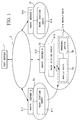
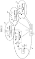
- Figure 1 shows a block diagram of the structure of the system in Embodiment 1.
- the system includes: a host server 1; a network 2 connected to the host server 1; radio server 3-1 ⁇ -3 connected to the network 2; sub-networks 2a, 2e, 2f which are managed by the radio servers 3-1 ⁇ 3; and base station radios 4-1, 4-5, 4-6 connected to respective radio servers 3-1 ⁇ 3.
- a plurality of immobile base station radios 4-n are connected to one radio server 3-n, but in this illustration, only one station device 4-n is shown for one radio server 3-n.
- the system serves mobile units represented, in this case, by one mobile unit 5-1, connected to the radio server 3-2 for wireless communication with the base station radios 4-5.
- the mobile unit 5-1 includes a mobile radio 5a and a computer terminal (referred to hereinbelow as the terminal device) 5b connected to the mobile radio 5a.
- the host server 1 may be a radio server to communicate with the terminal, but it does not necessarily have a wireless communication function.
- any one of the radio servers 3-n connected to the network 2 can serve as the home server for the mobile unit 5-1.
- the radio server 3-3 is designated as the home server for the mobile unit 5-1.
- FIG 2 illustrates the operation of the radio server system to manage the movement of a mobile unit.
- Mailing destination is indicated by “dst” and mailing source is indicated by “src”.
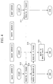
- Figures 3,4,5 and 6 are flowcharts for the operational steps of the radio server system.
- the home server for the mobile unit 5-1 is the radio server C3-3; and that the mobile unit 5-1 is presently operating under the direction of the radio server A3-1.
- the mobile unit 5-1 moves from sub-network 2a managed by the radio server A3-1 to sub-network 2e managed by the radio server B3-2.
- the mobile unit 5-1 requests a terminal registration approval and an IP address to radio server B3-2 (refer to (a) in Figure 2, step S1 in Figure 3).
- radio server B3-2 issues registration approval and an IP address (refer to (a), and step S2 in Figure 3), thus enabling the mobile unit 5-1 to operate under the radio server B3-2.
- radio server B3-2 notifies the radio server C3-3, which is the home server for the mobile unit 5-1, that the mobile unit 5-1 has moved from the managing district of radio server A3-1 to the managing district of radio server B3-2, and that the terminal registration has been effected (refer to (b) in Figure 2, and step S3 in Figure 3).
- the radio server C3-3 in response to the registration completion report from radio server B3-2, the radio server C3-3, as the home server, notifies radio server A3-1 that the mobile unit 5-1 has moved into the managing district of radio server B3-2 (step S5 in Figure 3). Accordingly, upon receiving the registration completion report from the radio server B3-2 (step S4 in Figure 3), radio server A3-1 stops managing the mobile unit 5-1 (step S6 in Figure 3). In the meantime, while a server C3-3 (home server) records that the mobile unit 5-1 is now in the managing district of B3-2, thereby updating the managing information (step S7 in Figure 3).
- the reason for using the home server C3-3 to notify radio server A3-1 that the mobile unit 5-1 has moved is that, by so doing, the home server will be able to recognize the managing district in which the mobile unit 5-1 is now operating.
- the mobile unit 5-1 can move about to other managing districts.
- the host server 1 transmits an IP packet through the network 2 (step S11 in Figure 4). At this time, because the host server 1 has not been notified of the movement of the mobile unit 5-1 to managing district B3-2, the packet is sent to radio server A3-1 to which the mobile unit 5-1 had been connected previously (refer to (c) in Figure 2).
- radio server B3-2 Upon receiving the packet in radio server A3-1 (step S11 in Figure 4), the packet is routed to radio server B3-2 (step S13 in Figure 3, and (d) in Figure 2), and are received by radio server B3-2 (step S14 in Figure 4). Further, radio server B3-2 routes the packet to the mobile radio 5a of the mobile unit 5-1 which is operating within its managing district (step S15 in Figure 4), and the packet is delivered to the mobile radio 5a (refer to (e) in Figure 2), and from there to the terminal device 5b (refer to (f) in Figure 2).
- the packet forwarded from the host server 1 is thus received by the mobile unit 5-1.
- the terminal device 5b transmits a packet to the mobile radio 5a((g) in Figure 2).
- the mobile radio 5a transmits the packet to the host server 1 by way of the radio server B3-2 ((h) in Figure 2).
- radio server B3-2 receives the packet (step S21 in Figure 5) and routes the packet to the host server 1 and sends the packet received from the mobile unit 5-1 to the host server 1 ((i) in Figure 2, step S22 in Figure 5).
- the host server 1 receives the packet (step S23 in Figure 5). Upon receiving the packet, the host server 1 now knows that the mobile unit 5-1 is in the managing district of radio server B3-2 because of the source address of the packet (step S24 in Figure 5).
- the radio server B3-2 receives the packet (step S32 in Figure 6), and routes it to the mobile unit 5-1 (step S33 in Figure 6) and delivers the packet to the mobile radio 5a ((k) in Figure 2), from which the packet is sent to the terminal device 5b ((m) in Figure 2).
- the above manner of informing the host server only when a packet is sent from the mobile unit 5-1 provides an advantage of avoiding congestion of data traffic, because of the elimination of the necessity of informing all the host servers on each move of the mobile unit 5-1.
- the mobile unit 5-1 moves into the managing district of radio server B3-2, it sends an IP address request to the radio server B3-2.
- the radio server B3-2 deduces the home server for the mobile unit 5-1 (radio server C is the home server in this case), and sends an IP address request to the radio server C3-3.
- DHCP radio server 6-3 which is a radio server for issuing IP addresses and is connected to the radio server C3-2 (home server).
- DHCP radio server 6-3 issues an IP address presently available for use, and the radio server C3-3 is informed of the IP address issued.
- the radio server C3-3 forwards the issued IP address to the mobile unit 5-1 by way of the radio server B3-2.
- the above process of issuing an IP address provides an advantage that even when the mobile unit 5-1 is operating under the managing district of radio server B3-2, an IP address issued by the radio server C3-3 can be used as though the mobile unit 5-1 is operating in the managing district of radio server C3-3, so that the packet transmission to the mobile unit 5-1 is allowed to be carried out by way of the radio server B3-2.
- the mobile unit 5-1 sends a terminal registration request and its identifier number to the radio server B3-2 ((a in Figure 9).
- the radio server B3-2 searches in the database 7-2 connected to the radio server B3-2 to find out whether or not the identification data of the mobile unit 5-1 is included. If the identification data do not exit in the database 7-2, the radio server B3-2 judges that it is not the home server for the mobile unit 5-1, and deduces the home server for the mobile unit 5-1 according to the identifier number received, and transfers the approval request to the home server (in this case, radio server C3-3) ((b) in Figure 9).
- the home server in this case, radio server C3-3) ((b) in Figure 9).
- the terminal registration request is sent to a pre-determined radio server (radio server A3-1, in this case). If the identifier number is not included in the database 7-1 of radio server A3-1, the terminal registration request is sent to a predetermined radio server (radio server (C3-3, in this case). These actions are repeated until the home server of the mobile unit 5-1 is notified of the terminal registration.
- the registration request is accompanied by the identifier number of the mobile unit 5-1 and a random number generated by the radio server B3-2. This random number is sent to the mobile unit 5-1 also ((c) in Figure 9).
- the radio server C3-2 which is the home server for the mobile unit 5-1 receives the approval request, and performs an approval computation using the random number and the identifier number received from the radio server B3-2.
- the radio server C3-3 returns the result of approval computation to the radio server B3-2 (d) in Figure 9).
- the mobile unit 5-1 performs an approval computation using the random number received from the radio server B3-2, and returns the result to the radio server B3-2((e) in Figure 9).
- the radio server B3-2 compares the results of approval computation received from the radio server B3-2 and the mobile unit 5-1 ((f) in Figure 9). Then, when the check process shows that the two are identical, the registration request is approved ((g) in Figure 9). If the check reveals that the two are not identical, it regards that the registration request is improper, and denies the approval request.
- approval operation consists only of "registration request” ((a) in Figure 9), “approval request” ((c) in Figure 9), “approval response” ((e) in Figure 9), “registration acceptance” ((g) in Figure 9).
- approval for a terminal registration for the mobile unit 5-1 can be carried out even when the mobile unit 5-1 is not under the managing district of a radio server which is its home server.
- FIG. 10 shows a block diagram of the structure of the radio server B3-2 including a network connection section 3a for connecting to the network 2; a relay agent section 3b for sending an address request to DHCP radio server 6-3, in response to an IP address request sent from the mobile unit 5-1, and receiving the IP address issued by DHCP radio server 6-3; a terminal connection section 3c for establishing communication with the mobile unit 5-1 by way of the base station radio 4-5; and a home server defining section 3d for defining the home servers for individual mobile radios.
- a network connection section 3a for connecting to the network 2
- a relay agent section 3b for sending an address request to DHCP radio server 6-3, in response to an IP address request sent from the mobile unit 5-1, and receiving the IP address issued by DHCP radio server 6-3
- a terminal connection section 3c for establishing communication with the mobile unit 5-1 by way of the base station radio 4-5
- a home server defining section 3d for defining the home servers for individual mobile radios.
- Figure 11 shows a flowchart showing the steps taken by the radio server B3-2.
- the terminal connection section 3c in the radio server B3-2 receives an IP address request sent from the mobile unit 5-1 by way of the base station radio 4-5 (step S41).
- the mobile unit 5-1 broadcasts (meaning sending the same packet simultaneously to all the devices connected within the network) the IP address request.
- the radio server B3-2 judges whether the IP address request is from the mobile unit 5-1, and if it is, the IP address request is accepted.
- the IP address request packet includes the identifier ID for the mobile unit 5-1 that is sending the request.
- the identifier ID is a media access control (MAC) address belonging to the mobile unit 5-1.
- a MAC address is an identifier number allocated to the hardware of the mobile unit 5-1.
- the terminal connection section 3c forwards the received packed to the relay agent section 3b.
- the relay agent section 3b extracts from its content the identifier ID of the mobile unit 5-1, and by consulting the contents of the home server defining section 3d, deduces an identifier ID to correspond to the mobile radio making the request (step S42).
- the home server defining section 3d is provided with a table relating identifiers IDs of individual mobile unit 5-1 and the IP addresses of home servers of mobile unit 5-1 corresponding to the identifier IDs. By consulting the table, the relay agent section 3b deduces the IP address of the home server for the mobile unit 5-1 having the identifier ID received therein.
- the relay agent section 3b sends an IP address request packet on behalf of the mobile unit 5-1 to the home server (radio server C3-3 in this case) through the network connection section 3a (step S43).
- the source address of the sent packet is the IP address of the radio server B3-2
- the destination address is the IP address of the deduced home server.
- the IP address request is sent to a pre-determined radio server (A-3, in this case). If the data do not exist in the home server defining section 3d of the second radio server, the IP address request is sent to another pre-determined radio server (C3-3, in this case). By repeating the steps until the home server of the mobile unit 5-1 is found, the IP address request is delivered to the home server of the mobile unit 5-1. Accordingly, a home server for a mobile unit can be deduced under any circumstance.
- the radio server C3-3 receiving the IP address request packet sends an IP address request to the DHCP radio server 6-3.
- the DHCP radio server 6-3 issues an IP address presently available for use, and sends it to the radio server C3-3.
- the radio server C3-3 sends the packet containing the IP address issued by the DHCP radio server 6-3 to the radio server B3-2 that sent the IP address request packet.
- the network connection section 3a receives the packet sent by the radio server C3-3 (step S44).
- the network connection section 3a judges whether the received packet is a response packet replying to the IP address request, and when it is the response packet, the packet is forwarded to the relay agent section 3b.
- the relay agent section 3b receiving the response packet from the network connection section 3a attaches the identifier ID of the mobile unit 5-1, and forwards the packet to the terminal connection section 3c.
- the terminal connection section 3c distributes the response packet to the mobile unit 5-1 broadcasting (step S45). Then, the mobile unit 5-1 checks whether the identifier ID is included in the broadcast packet for the mobile unit 5-1, and if it is contained, the mobile unit 5-1 extracts the IP address from the packet.
- the process of issuing an IP address to mobile unit 5-1 presently requesting an IP address, from a radio server that is not the home server provides an advantage that any mobile unit is able to access any other radio servers without changing the settings of the IP address of the mobile unit 5-1.
- normal broadcasting systems do not allow a mobile unit to broadcast beyond own network (with which it is presently communicating) to other mobile units connected to other networks.
- the present broadcast system allows an IP address request to be made to a DHCP radio server connected to any network, because of the provision of a relay agent section for sending/receiving an IP address request packet on behalf of the mobile unit.
- IP address for the radio server B3-2 is assumed to be, for example, [172.31.0254]
- IP addresses for the base station radios 4-2 ⁇ 5 to be [172.31.31.254], [172.31.47.254], [172.31.63.254][172.31.79.254], respectively.
- an IP address of one mobile radio 5a among the many mobile radios communicating with the base station radios 4-2 ⁇ 5 is assumed to be [172.31.0.1].
- IP address is usually expressed in 32-bits and decimal notation, and each group of 8-bits is separated by a period [.].
- the third numerals [31], [47], [63], and [79], in the base station radios 4-2 ⁇ 5, are expressed so that the higher 4-bits are [0001], [0010], [0011], [0100] and all the lower bits are [1111].
- the third and fourth numeral for all the base station radios are pre-selected for each device by the respective radio server.
- all the base station radios can be expressed as [11111110] (representing 254 in decimal notation).
- the lower 4-bits in the third numeral and the numeral [1111 1111 1110] represented by the fourth numeral indicate that this device is a base station radio, and the upper 4-bits in the third numeral distinguish individual base station radios.
- the first numeral and the second numeral represent the radio server B3-2 to which the base station radios 4-2 ⁇ 5 are connected.
- IP addresses allow to identify a radio server connected to each of the base station radios 4-2 ⁇ 5 as well as to identify the numerical order of the devices within the station.
- the lower 12-bits of the 32-bit IP address are assigned by the radio server B3-2. Therefore, it is possible to know to which base station radio the mobile radio 5a is connected, by selecting an IP address for the mobile radio 5a according to the IP addresses assigned to the radio server B3-2 and the base station radios 4-2 ⁇ 5.
- the above manner of informing the host server only when packet transfer occurs from the wireless mobile unit provides an advantage of avoiding congestion of data traffic, because of the elimination of the necessity of informing all the host servers for each move of the mobile unit 5-1.
- IP addresses are allocated also to the base station radios so that the Internet protocol and ISDN routers can be used for communicating between the terminal devices and the radio server, thereby enabling the communications to be maintained regardless of the separation distance between the radio server and the base station radios, without having to alter the configuration of the system.
- Figure 13 shows a block diagram of the overall structure of the system including: a broadcasting terminal 1a for preparing and broadcasting information; a radio server B3-2 connected to the terminal 1a by a network 2; four base station radios 4-2 ⁇ 5 connected to the radio server B3-2; and individual mobile units 5-1 ⁇ 4 communicate with the respective base station radios 4-2 ⁇ 5.
- one mobile unit 5-1 is shown for each base station radio 4-2, for example, one station device may communicate with more than two mobile unit 5-1.
- Broadcasting means distributing the same information to a plurality of terminal devices simultaneously.
- the operator prepares information for broadcasting using the terminal 1a.
- broadcasting information is comprised by a header section and a plurality of information. In this case, it is assumed that the information is divided into four sections.
- an identifier to indicate that the information is to be broadcast, network addresses for delivery of information, and sizes of the information files 1 ⁇ 4 that follow the header section.
- the broadcast information is divided into a plurality of reception levels according to the subject matter.
- the information is divided into four groups.
- Dividing according to the reception levels can be explained using an example of broadcasting an emergency message according to the type of terminal devices as follows: those belonging to individual persons (level 1), those belonging to self-governing bodies (level 3), those belonging to fire departments (level 7), and those belonging to police (level 15).
- the terminals receiving broadcasting information are divided into pre-arranged reception levels, and are identified by the level numbers (referred to as broadcast levels).
- bits are assigned to information 1 ⁇ 4 to indicate the broadcast levels, so that when the bit is [1], the information is needed by the terminal having this level number.
- Information 1 is allocated to the lowest bit and information 4 is allocated to the highest bit.
- level number For example, for those terminals requiring only information 1, only the lowest bit is [1] so that the level number is [1]. For those terminals requiring all the information 1 ⁇ 4, all four bits are [1] so that the level number is [15]. For those terminals requiring no information, level number is [0].
- bit number can be increased to increase the number of levels.
- Broadcast information is prepared by separating the information into a plurality of levels according to the broadcast levels.
- broadcasting terminal 1a broadcasts the prepared information to a specified network 2.
- the network to be broadcast is not limited to the network connected to the broadcasting terminal 1a, but can be selected by specifying other network addresses.
- the broadcasting terminal may be constructed using a computer device having input/output means.
- Figure 14 shows a block diagram of the structure of the radio server B3-2
- Figure 16 shows a flowchart of the steps taken by the radio server B3-2.
- a broadcast information receiving section 3e provided in the radio server B3-2 receives broadcast information distributed by the broadcasting terminal 1a (step S46) and stores this information in a broadcast information receiving section 3e.
- the broadcast information receiving section 3e judges whether or not this is broadcast information depending on whether or not the identifier is included in the header to indicate that it is broadcast information.
- the broadcast information reconstruction section 3f accesses the information stored in the broadcast information receiving section 3e, while consulting the broadcast level defining section 3i, and reconstructs broadcast information so as to match the broadcast levels of the connected mobile units 5-1 ⁇ 4 (step S47).
- Reconstruction of broadcast information means that the types of information not needed by the mobile unit 5-1 are eliminated so that the mobile units 5-1 ⁇ 4 may receive only the necessary information.
- the broadcast level defining section 3i there are defined the level numbers of the broadcast levels and communication channels of the mobile units 5-1 ⁇ 4 presently communicating with the radio server B3-2.
- the channel selection section 3g refers to the broadcast level defining section 3i, and selects channels to correspond to the individual mobile units 5-1 ⁇ 4 (step S48) and forwards the reconstructed broadcast information to a sending section 3h.
- the sending section 3h transmits the broadcast information through a channel selected by the channel section 3g to the individual mobile units 5-1 ⁇ 4 (step S49).
- the channel selection section 3g may transmit the packets by changing the receiver addresses to the addresses of the mobile unit 5-1.
- the radio server B3-2 receives the grouped broadcast information, the radio server B3-2 reconstructs broadcast information according to the broadcast levels of the mobile units 5-1 ⁇ 4, and transmits only the relevant information to the mobile units 5-1 ⁇ 4, so that the system can operate more efficiently.
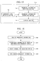
- Figure 15 shows a block diagram of the structure of the mobile unit 5-1
- Figure 17 shows a flowchart of the steps taken by the mobile unit 5-1.
- broadcast information is prepared by the broadcasting terminal 1a, and the information is broadcast within the network 2. Then, the radio server B3-2 receiving the broadcast information distributes the information in the as-received condition.
- mobile unit 5-1 is chosen as the representative terminal.
- the receiving section (mobile device) 5a provided in the mobile unit 5-1 receives this information (step S51), and holds it in the receiving section 5a.
- the receiving section 5a recognizes whether or not the information is broadcast information according to whether or not the broadcast identifier is included in the header section.
- the information extraction section 5b accesses the broadcast information stored in the receiving section 5a, while consulting the broadcast level defining section 5d, and extracts only the necessary information for the mobile unit 5-1 (step S52).
- the information extraction section 5b displays the extracted information on a display section 5c (step S53).
- the broadcasting terminal can select what information to be delivered to a mobile unit 5-1, thus improving the information delivery efficiency.
- terminal devices communicating with the radio server B3-2 may include wired devices.
- terminal configuration shown in Figure 15 can be applied to wired devices.
- the mobile unit 5-1 shown in Figure 12 may communicate directly with a network 2.
- broadcast information is not limited to text data, other types of data such as audio data and customized signals are also applicable.
- the display section 5c shown in Figure 15 may be replaced with a speaker device for generating sounds, or an alarm device for generating an alarm sound in response to customized signals.
- Embodiment 5 relating to a multi-cast system in which same information is distributed to a plurality of mobile units 5-1, will be explained with reference to Figures 1, 13, 19 and 20.
- multi-casting transmits the same information simultaneously to specified mobile units.
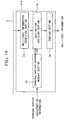
- Figure 19 shows a block diagram of the structure of the radio server B3-2, which includes: a multi-cast information receiving section 3j which received information through a network 2; a destination deciding section 3k for determining the delivery destinations; a sending section 3m for sending received information to the mobile unit 5-1; and a terminal information memory section 3n for storing information on home server of the mobile unit 5-1 and a radio server presently being connected.
- Figure 20 shows a flowchart of the steps of distributing multi-cast information to the mobile unit 5-1.
- the mobile unit 5-1 to communicate with the radio server A3-1, radio server B3-2, the radio server C3-3 shown in Figure 1 have been classified into groups for receiving multi-cast information, and are provided with group identifiers ID.
- the group IDs are managed by the home servers for each of the mobile units 5-n, and a client table containing terminal IDs and group IDs for the mobile unit 5-n is included in the terminal information memory section 3n of each home server.
- the mobile unit 5-1 transmits a terminal registration request to the radio server B3-2.
- the mobile unit 5-1 transmits its terminal ID.
- the radio server B3-2 carries out terminal registration process as described earlier.
- the radio server B3-2 reports particulars of the mobile unit 5-1 to the home server (in this case radio server C3-3), which registers this information.
- the home server (radio server C3-3) is able to obtain an identification of the radio server presently communicating with the mobile unit 5-1 that is requesting a terminal registration, and the group ID of the mobile unit 5-1.
- the home server reports to the radio server B3-2 the group ID of the mobile unit 5-1 registered presently.
- the radio server B3-2 registers the group ID in the terminal information memory section 3n.
- this process results in the terminal information memory section 3n in the radio server B3-2 to store a plurality of group IDs for those mobile units 5-n whose home server is the radio server B3-2 as well as those mobile unit 5-n whose home servers are other radio servers located in other terminal managing districts.
- a mobile unit 5-n prepares multi-cast packet.
- the packet contains an identifier to indicate that the information is to be multi-cast, and address of the destination network and group ID for information distribution.
- the packet is then transmitted to the destination network. It should be noted that the mobile unit 5-n preparing multi-cast information can be connected to any network and the information can be delivered to any destination network.
- the information receiving section 3j provided in the radio server B3-2 receives multi-cast information (step S61). At this time, the information receiving section 3j judges whether or not the information is multi-cast information on the basis of whether or not the identifier ID indicating multi-casting is included in the header. The received multi-cast information is stored in the information receiving section 3j.
- destination deciding section 3k accesses the multi-cast information stored in the information receiving section 3j, while consulting the contents of the memory of the terminal information memory section 3n, to decide the delivery destination (step S62). At this time, the destination deciding section 3k selects mobile units for packet delivery, by extracting the group ID contained in the multi-cast information, and extracting those mobile units having the same group ID by referring to the content of the terminal information memory section 3n. Packet delivery is made to those terminals that are presently communicating with the radio server B3-2 if they have the same group ID. If they are not presently communicating, delivery is made later when they are connected.
- the destination deciding section 3k deduces the radio server which is presently communicating with the mobile unit 5-1, and designates this radio server to be a packet delivery destination.
- the destination deciding section 3k transmits multi-cast information received in the information receiving section 3j to individual mobile units 5-n through the sending section 3m (step S63).
- the features of this system are that the reference is made to the terminal information memory section 3n to decide the mobile units for receiving multi-cast information, and that the reliability of information delivery is assured because multi-cast information can be transferred to the correct destination, even when the mobile unit 5-1 is connected to another radio server.
- Computer system in this context, includes any operating systems and peripheral hardwares that are connected (remotely or directly) to networks.
- Computer-readable recording media include portable media such as floppy discs, opto-magnetic discs, ROM, CD-ROM, as well as fixed devices such as hard discs housed in computer systems.
- Computer-readable recording media include short-term dynamic memories used in transmitting programs and data through communication circuits such as Internet or telephone circuits, as well as other short-term memories such as volatile memories used in servers and client computer systems.
- Application program may perform a part of the described functions, or may be operated in conjunction with pre-recorded programs stored in computer systems.
- a computer-readable recording medium containing a relay agent program for processing an IP address request should include functions so that the computer can execute tasks such as: processing an IP address request from a mobile radio; deducing a home server of the requesting wireless mobile according to a request content; issuing an IP address request on behalf of the requesting mobile radio; receiving an IP address issued by the home server; and distributing the received IP address to the requesting mobile radio.
- a computer-readable recording medium containing a terminal connection program for processing a terminal connection request should include approval functions so that the computer can execute tasks such as: identifying a terminal in response to a terminal registration request; issuing an IP address that is presently available for use.
- the terminal connection program should further include packet transfer functions so that the computer can execute a task that, when a terminal device moves from a previously-connected radio server to a presently communicating radio server that is not its home server, and packet data addressed to the terminal device are delivered to the presently communicating radio server that is not its home server, then the packet data are routed to the presently communicating radio server according to the IP address obtained from the home server of the subject terminal device.
- the terminal connection program should further include routing functions so that the computer can execute a task that, when the subject terminal device is presently communicating with a radio server that is not its home server, and packet data are transferred to the wireless terminal, a host server on the Internet that routed the packet data is advised of the identity of the presently communicating radio server so that subsequent packet data are routed to the presently communicating radio server.
- a computer-readable recording medium containing a broadcasting program for distributing information should include broadcasting functions so that the computer can execute tasks such as: receiving distributed broadcast information; extracting from the received broadcast information only the necessary information for the subject terminal device, while consulting the contents of the broadcast level defining section; and displaying only the required information on a display section of the subject terminal device.
- a computer-readable recording medium containing a multi-cast program for distributing information should include multi-casting functions so that the computer can execute tasks such as: receiving multi-cast data; deciding distribution destinations for the multi-cast data by consulting terminal information; and distributing multi-cast data according to decided delivery destinations.
- the present radio server system enables a mobile unit to continue to communicate in different managing districts so that this technologies can be utilized in the field such as: messages (such as e-mail, netnews, file transfer protocol (FTP)), voice mail, web broadcasting, computer telephony integration (CTI), information broadcasting, telemetering, intelligent transport system (ITS). Also, the system is applicable to the push-technology when used in conjunction with routing functions.
- messages such as e-mail, netnews, file transfer protocol (FTP)
- voice mail such as e-mail, netnews, file transfer protocol (FTP)
- CTI computer telephony integration
- ITS intelligent transport system
- the system is applicable to the push-technology when used in conjunction with routing functions.
- the base station radio 4-n and the mobile unit 5-1 shown in Figure 1 will be explained with reference to Figures 21-24.
- Figure 21 shows a block diagram of the overall configuration of the radio server system which includes: a radio server B3-2; a plurality of base station radios 4-2 ⁇ 5, wire-connected to the radio server B3-2 using sending frequencies f1 ⁇ f3; a mobile unit 5-1 for wireless communication with the base station radio 4-5 which uses a sending frequency f0.
- the mobile unit 5-1 is comprised by a mobile radio 5a and a terminal device 5b and uses a sending frequency F0.
- the sending frequencies f0 ⁇ f3 of the base station radios 4-2 ⁇ 5 are termed the down-frequencies, and the sending frequency F0 of the mobile radio is termed the up-frequency.
- Figure 22 shows a block diagram of the configuration of the base station radios 4-2 ⁇ 5 comprised by: a server data receiving section 11 for receiving data sent from the radio server B; a memory section 12 for storing the data received in the server data receiving section 11; a ROM 13 for storing operational frequencies containing a plurality of values of up-frequency 13a and down-frequency 13b; judging sections 14, 15 for comparing data sent from radio server B with data stored in ROM of a base station radio 4-n, and output results of comparison; a sending data preparation section 17 for receiving results of the judging sections 14, 15 and preparing sending data to be sent from the station device 4-n; a modulation section 17 for modulating the data; and a signal output section 18 for sending the modulated data produced by the modulation section 17.
- a server data receiving section 11 for receiving data sent from the radio server B
- a memory section 12 for storing the data received in the server data receiving section 11
- a ROM 13 for storing operational frequencies containing a plurality of values of up-frequency 13a
- Fig. 23 shows a block diagram of the configuration of the mobile unit 5-1 shown in Figure 21 comprised by: a signal receiving section 21 for receiving signals sent from the base station radio 4-n; a demodulator 22 for demodulating the received data; a received signal analysis section 23; a memory section 24 for storing the operational frequencies; a frequency selection section 25 for selecting receiving frequency; a priority setting section 26 for selecting the order of receiving frequencies by the frequency selection section; a ROM 27 for storing frequencies that can be received by the mobile unit 5-1; and judging section 28 for judging the sending frequency that can be used by the mobile unit 5-1.
- base station radio 4-5 is used as an example.
- the radio server B3-2 managing the base station radios 4-2 ⁇ 5, informs each of the base station radios 4-2 ⁇ 5 what operational frequency can be used. At this time, the radio server B3-2 transmits the same information to all the base station radios 4-2 ⁇ 5, thereby enabling the base station radios 4-2 ⁇ 5 to know the operational frequencies of the other base station radios.
- the server data receiving section 11 provided in the base station radio 4-5 receives the down-frequency information sent by the radio server B-3-2. Then, the server data receiving section 11 stores the received information in the memory section 12. Then, the server data receiving section 11 stores data received by the peripheral base station radios (in this case, base station radios 4-2 ⁇ 4) separately as up-frequency 12a for peripheral base station radios, up-frequency 12b and down-frequency 12c for own device.
- the peripheral base station radios in this case, base station radios 4-2 ⁇ 4
- the judging section 14 compares up-frequency 13a stored in ROM 13 with own up-frequency 12b stored in the memory section 12. If the result shows that the own up-frequency 12b sent from the radio server B3-2 is a permissible frequency, this up-frequency 12b is forwarded to the sending data preparation section 16.
- the judging section 15 compares down-frequency 13b stored in ROM 13 with the own down-frequency stored in the memory section 12. If the result shows that the own down-frequency 12c sent from the radio server B3-2 is a permissible frequency, the down-frequency 12c is forwarded to the sending data preparation section 16 and the modulation section 17.
- the sending data preparation section 16 converts up- and down-frequency information received from the judging sections 14, 15 to sending data. Concurrently, the sending data preparation section 16 converts information regarding the down-frequencies 12a for the peripheral base station radios to sending data. Then, the sending data preparation section 16 forwards the converted sending data to the modulation section 17.
- the modulation section 17 uses the down-frequency received from the judging section 15 to modulate the sending data prepared by the sending data preparation section 16.
- the modulated sending data are sent from the signal sending section 18.
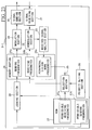
- Figure 24 shows a flowchart of the steps taken by the mobile unit 5-1.
- the demodulation section 22 uses a receiving frequency 24b stored in the memory section 24 to attempt to receive signals from the signal receiving section 21 (step S101).
- This receiving frequency 24b is the frequency which was last-used for communication.
- step S102 it is examined whether the signal reception by the demodulator 22 was successful (step S102), and if successful, the received signal is demodulated and is forwarded to the received signal analysis section 23.
- the received signal analysis section 23 analyzes the received signal, and stores the down-frequency of the peripheral base station radio in the memory section 24 and obtains up-frequency (step S103) which is forwarded to the judging section 28.
- the judging section 28 accesses the permissible sending frequencies 27b stored in ROM 27, and compares with the up-frequency received from the received signal analysis section 13, and checks whether the up-frequency received is permissible for signal transmission (step S104). This judgment is based on whether the received up-frequency matches the sending frequencies 27b stored in ROM 27. If the result indicates that it can be sent, the judging section 28 stores the up-frequency in the memory section 24. Then, the modulation section 29 uses the sending frequency 24a stored in the memory section 24 to send the registration request from the mobile unit 5-1 (step S105). Also, when there is no need for sending the terminal registration, it is possible to eliminate the step of sending the request.
- the registration request is sent by having the modulation section 29 access the sending frequency stored in the memory section 24, and sending the signal from the signal sending section 30 at this frequency.
- the use of the last-used frequency to obtain the up-frequency enables to commence communication without performing the frequency selection step.
- the selection section 25 checks the down-frequencies 24c of the peripheral base station radio stored in the memory 24, and selects a receiving frequency according to the priority order stored in the priority setting section 26 (step S106). At this time, the selection section 25 compares the selected receiving frequency with the permissible receiving frequencies stored in the memory 27, and if the selected receiving frequency is a permissible frequency, this frequency is stored in the memory section 24.
- the demodulation section 22 uses the receiving frequency 24b stored in the memory section 24 to check whether the signal reception was successful (step S107), and if it was successful, received signal is demodulated which is forwarded to the received signal analysis section 23.
- the received signal analysis section 23 analyzes the received signal, and stores peripheral down-frequency in the memory section 24, and concurrently, obtains the up-frequency (step S108) which is forwarded to the judging section 28.
- the judging section 28 accesses the permissible sending frequencies 27b stored in ROM 27, and compares them with the up-frequency received from the received signal analysis section 23, and checks whether the up-frequency received is permissible for signal sending (step S109). This judgment is based on whether the received up-frequency matches the sending frequencies 27b stored in ROM 27. If the result indicates that it can be sent, the judging section 28 stores the up-frequency in the memory section 24. Then, the modulation section 29 uses the sending frequency 24a stored in the memory section 24 to send the registration request from the mobile unit 5-1 (step S105). Also, when there is no need for sending the terminal registration, it is possible to eliminate the step of sending the request.
- step S110 if the signal reception was not possible in step S107 and if the up-frequency is not the permissible frequency in step S109, steps S106 ⁇ S109 are repeated (step S110).
- step S110 if there are no other candidates for the permissible down-frequencies, the selection section 25 checks the permissible receiving frequencies 27a stored in ROM 27, and selects a receiving frequency according to the priority order stored in the priority order setting section 26 (step S111), which is stored in the memory section 24.
- the demodulation section 22 uses the receiving frequency 24b stored in the memory section 24 to check whether the signal reception was successful (step S112), and if it was successful, received signal is demodulated which is forwarded to the received signal analysis section 23.
- the received signal analysis section 23 analyzes the received signal, and stores peripheral down-frequency in the memory section 24, and concurrently, obtains the up-frequency (step S113) which is forwarded to the judging section 28.
- the judging section 28 accesses the permissible sending frequencies 27b stored in ROM 27, and compares them with the up-frequency received from the received signal analysis section 23, and checks whether the up-frequency received is permissible for signal sending (step S114). This judgment is based on whether the received up-frequency matches the sending frequencies 27b stored in ROM 27. If the result indicates that it can be sent, the judging section 28 stores the up-frequency in the memory section 24. Then, the modulation section 29 uses the sending frequency 24a stored in the memory section 24 to send the registration request from the mobile unit 5-1 (step S105). Also, when there is no need for sending the terminal registration, it is possible to eliminate the step of sending the request.
- step S115 if signal reception was not possible in step S112 or if the up-frequency is not the permissible frequency in step S114, steps S111 ⁇ S114 are repeated (step S115).
- step S115 if there are no other permissible receiving frequencies, the mobile unit 5-1 is not able to use the present managing district so that it is necessary to move to another managing district, and attempt the steps shown in Figure 24.
- the mobile unit 5-1 when the base station radio 4-5 shown in Figure 21 has commenced communicating with another mobile unit, the mobile unit 5-1 is in a standby state. In this condition, if the mobile unit 5-1 tries to send a packet to the radio server B3-2, the base station radio 4-5 cannot be accessed. In such a case, the mobile unit 5-1, using a receiving frequency of a peripheral station device (base station radio 4-2 ⁇ 4, in this case) obtained in step S101 ( Figure 24) and stored in the memory section 24, acquires a sending frequency of the base station radio 4-4-2 by following the steps S106 ⁇ S109. This approach permits the mobile unit 5-1 to communicate immediately with the base station radio 4-4-2 without changing the radio server B3-2, thus eliminating the necessity for the step of terminal registration ( Figure 24).
- a peripheral station device base station radio 4-2 ⁇ 4
- a packet can be sent out immediately without having to receive a new sending frequency of the base station radio 4-2.
- Figure 25 shows a block diagram of the configuration of the mobile unit 5-1. The differences of this configuration and that shown in Figure 23 are that a priority table 24d is provided in the memory section 24 and that a priority table generation section 26a, for generating a priority table 24d, is provided on the basis of permissible receiving frequencies 27a residing in ROM 27.
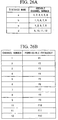
- FIG 26 shows an example of the structure of the table containing the permissible receiving frequencies 27a stored in ROM 27 shown in Figure 25.
- permissible receiving frequencies 27a are comprised by two tables.
- Permissible channel table shown in Figure 26A includes a district name field and a channel number field.
- the district name is used to distinguish the districts in which the radio server B3.2 and the base station radios 4-2 ⁇ 5 are operating, so that for one radio server B3-2, there is a managing district name.
- Channel numbers define channels that can be used in each district, and in the district [a] for example, channel numbers 1, 2, 3, 4, 5 and 6 are operable.
- the frequency table shown in Figure 26B includes the channel number field and the permissible receiving frequency field.
- the channel numbers are logical numbers allocated to each permissible receiving frequencies, and it is assumed, in this case, that the mobile unit 5-1 are able to use permissible receiving frequencies f1 ⁇ f12 corresponding to channel numbers 1 ⁇ 12.
- Figure 27 shows the structure of the priority table 24d stored in the memory section 24.
- the priority table 24d includes a channel number field, a district name field, a number of districts field, a permissible receiving frequency field.
- the district names relate to those districts using the frequencies of the assigned channel numbers. For example, in Figure 27, channel number 1 is used in districts a, b, c, so that the number of the districts is three.
- the priority table generation section 26a when the power is turned on for the mobile unit 5-1, the priority table generation section 26a generates a priority table 24d in the memory section 24 by consulting the permissible receiving frequencies 27a stored in ROM 27. The process of generating the priority table 24d will be explained in the following.
- the priority table generation section 26a accesses the permissible receiving frequency table (refer to Figure 26B) of the permissible receiving frequencies 27a stored in ROM 27, and enters the values in the respective fields in the priority table 24d. At this point, the channels numbers and permissible receiving frequencies become listed in respective fields of the priority table 24d, as shown in Figure 28.
- the priority table generation section 26a accesses the permissible frequency table ( Figure 26A) of the permissible receiving frequencies 27a stored in ROM 27, and enters the values in the respective fields in the priority table 24d. At this time, the priority table generation section 26a extracts district names using the channel numbers and enters the values in the district name field. In the example shown in Figure 26, channel number [1] is operating in district names [a], [b] and [c], therefore [a], [b], [c] are entered in the district name field corresponding to channel 1 in the priority table 24d.
- the district names using channel numbers [1] ⁇ [12] are entered in the district name field.
- the priority table generation section 26a counts the number of districts using each channel number, and the results are entered in the number of district field. At this point, for each channel number, the district names using the channel number and the number of districts using each channel number become listed in the priority table 24d.
- the priority table generation section 26a rearranges the data using the number of districts as the sort key so that the table shows a descending order of channel usage, listing the most frequently used channels at the top, thereby preparing the priority order table 24d shown in Figure 27.
- the priority table 24d shown in Figure 27 is prepared from the data in the permissible receiving frequency table and the permissible channel table giving the permissible receiving frequencies 27a shown in Figure 26.
- step S111 the step of selecting a permissible receiving frequency stored in ROM
- step S111b the step of selecting a permissible receiving frequency in the priority table
- steps S101 ⁇ S110 are the same as the steps S1 ⁇ S10 in Figure 24, therefore, explanations are omitted.
- step S101 is executed after the priority table 24d is generated.
- step S110 when there are no candidates for a down-frequency, the selection section 25 checks from the top data in the priority table 24d stored in memory section 24, through the priority setting action 26, and selects a frequency corresponding to a channel number and assigns this frequency as the receiving frequency (step S111b) and stores the frequency in the memory section 24.
- step S112 it is examined whether the signal reception by the demodulator 22 was successful (step S112), and if successful, the received signal is demodulated and is forwarded to the received signal analysis section 23.
- the received signal analysis section 23 analyzes the received signal, and stores down-frequency of the peripheral base station radio in the memory section 24 and obtains up-frequency (step S113) which is forwarded to the judging section 28.
- the judging section 28 reads the permissible sending frequencies 27b stored in ROM 27, and compares it with the up-frequency received from the received signal analysis section 23, and checks whether the up-frequency received is permissible for signal transmission (step S114). This judgment is based on whether the received up-frequency matches the sending frequencies 27b stored in ROM 27. If the result indicates that it can be sent, the judging section 28 stores the up-frequency in the memory section 24. Then, the modulation section 29 uses the sending frequency 24a stored in the memory section 24 to send the registration request from the mobile unit 5-1 (step S105). Also, when there is no need for sending the terminal registration, it is possible to eliminate the step of sending the request.
- step S115 if signal reception was not possible in step S112 or if the up-frequency is not the permissible frequency in step S114, steps S111 ⁇ S114 are repeated (step S115).
- step S115 if there are no other permissible receiving frequencies, the mobile unit 5-1 is not able to use the present managing district so that it is necessary to move to another managing district, and attempt the steps shown in Figure 24.
- steps S101 ⁇ 104 and S106 ⁇ S111 may be skipped, and after preparing the priority table 24d, step S111b may be executed immediately afterward.
- the mobile radio has information regarding the operational frequencies from the base station radios, if signal reception becomes difficult, information on the operational frequencies can be used to switch to another operational frequency. Switching the operational frequency provides an advantage that, because there is no change in the managing server for the mobile device, the connection can be maintained without having to go through the registration and approval processes even when communicating with other base station radios.
- chronological switching of operational frequency provides an advantage that redundant terminal registration can be avoided and the use of unauthorized up-frequencies can be avoided because only the permissible up-frequencies are accepted. Because the permissible frequencies and the operational frequencies of the station devices are stored in the mobile device in the order of popularity, the probability of accessing an operational frequency and the process of selecting an operational frequency are improved significantly.
- the programs shown in Figures 24, 29 may be recorded on a computer-readable recording media such as floppy discs, CD-ROM, opto-magnetic discs, IC cards, DVD-ROM, so that computer means can execute application programs to select an operational frequency.
- a computer-readable recording media such as floppy discs, CD-ROM, opto-magnetic discs, IC cards, DVD-ROM, so that computer means can execute application programs to select an operational frequency.
- the application programs are totally or partially recorded on portable memory media such as floppy discs and CD-ROM; and fixed memory devices such as hard discs.
- Application program may perform a part of the described functions, or may be operated in conjunction with pre-recorded programs stored in computer systems.
- Computer-readable recording media include not only static memories, such as opto-magnetic discs, but short-term dynamic memories used in transmitting programs and data through communication circuits such as Internet or telephone circuits, as well as other short-term memories such as volatile memories used in servers and client computer systems.
- a computer-readable recording medium containing a frequency selection program for a wireless mobile unit should include processing steps of: receiving a first up-frequency given by the base station radio using a last receiving frequency of the mobile radio; judging whether or not the first up-frequency is a permissible sending frequency for the mobile radio, so that, if the up-frequency is permissible, sending a terminal registration request to the base station radio using the up-frequency; however, if the last frequency is not useable, receiving a second up-frequency from a peripheral base station radio using a down-frequency allocated to the peripheral base station radio, judging whether or not the second up-frequency is a permissible sending frequency; and if the second up-frequency is permissible, sending the terminal registration request to the peripheral base station radio using the second up-frequency; however, if the last receiving frequency and the second down-frequency of the peripheral base station radio cannot be used by the mobile radio, then, searching in a memory section of the mobile radio for a permissible receiving frequency, by successively testing permissible receiving
- the subsequent steps presented above may be replaced with the following steps: searching for a receiving frequency that can be used by the mobile radio, by successively testing permissible receiving frequencies so as to find a station device whose down-frequency matches a permissible receiving frequency for the mobile radio, beginning with a down-frequency shared by the highest number of station devices until a receiving frequency that can be used by the mobile radio is found; receiving a third up-frequency from a station device using the receiving frequency; checking whether or not the third up-frequency received is a permissible sending frequency; and if it is permissible, sending the terminal registration to the base station radio that sent the third up-frequency.
- the above program may directly proceed to the step of: searching for a receiving frequency that can be used by the mobile radio, by successively testing permissible receiving frequencies so as to find a base station radio whose down-frequency matches a permissible receiving frequency for the mobile radio, beginning with a down-frequency shared by the highest number of base station radios until a receiving frequency that can be used by the mobile radio is found; receiving an up-frequency from a base station radio using the receiving frequency; checking whether or not the up-frequency received is a permissible sending frequency; and if it is permissible, sending the terminal registration to the base station radio that sent the up-frequency.
Landscapes
- Engineering & Computer Science (AREA)
- Computer Networks & Wireless Communication (AREA)
- Signal Processing (AREA)
- Computer Security & Cryptography (AREA)
- Mobile Radio Communication Systems (AREA)
Applications Claiming Priority (10)
| Application Number | Priority Date | Filing Date | Title |
|---|---|---|---|
| JP26209998 | 1998-09-16 | ||
| JP26209998 | 1998-09-16 | ||
| JP29459298 | 1998-09-30 | ||
| JP29459298 | 1998-09-30 | ||
| JP30923198A JP3284979B2 (ja) | 1998-09-16 | 1998-10-29 | 無線通信装置、無線通信方法及びその記録媒体 |
| JP30923198 | 1998-10-29 | ||
| JP30922898A JP3230155B2 (ja) | 1998-09-16 | 1998-10-29 | 無線通信装置及び記録媒体 |
| JP30922898 | 1998-10-29 | ||
| JP36165998A JP3417320B2 (ja) | 1998-09-30 | 1998-12-18 | 基地無線装置、移動無線装置、無線通信方法及び記録媒体 |
| JP36165998 | 1998-12-18 |
Publications (2)
| Publication Number | Publication Date |
|---|---|
| EP0987860A2 true EP0987860A2 (de) | 2000-03-22 |
| EP0987860A3 EP0987860A3 (de) | 2004-01-14 |
Family
ID=27530403
Family Applications (1)
| Application Number | Title | Priority Date | Filing Date |
|---|---|---|---|
| EP99117940A Withdrawn EP0987860A3 (de) | 1998-09-16 | 1999-09-14 | Funkserversystem |
Country Status (2)
| Country | Link |
|---|---|
| US (1) | US6542491B1 (de) |
| EP (1) | EP0987860A3 (de) |
Cited By (10)
| Publication number | Priority date | Publication date | Assignee | Title |
|---|---|---|---|---|
| WO2000042791A1 (en) * | 1999-01-13 | 2000-07-20 | Pentikaeinen Jaakko | Wirelesss network and methods to be used therein |
| WO2001091420A3 (en) * | 2000-05-25 | 2002-03-14 | Ericsson Telefon Ab L M | Ip address allocation in a mobile telecommunications network |
| WO2003051084A1 (en) * | 2001-12-11 | 2003-06-19 | Cisco Technology, Inc. | System and method for selecting a wireless serving node |
| WO2003061326A1 (en) * | 2002-01-11 | 2003-07-24 | Cisco Technology, Inc. | System and method for identifying a wireless serving node for a mobile unit |
| EP1355448A3 (de) * | 2002-04-19 | 2004-07-21 | Nokia Corporation | System und Verfahren zum Mitteilen von Informationen über die Netz-Konfiguration oder von zusätzlichen Informationen an drahtlose Terminals |
| GB2367925B (en) * | 2000-05-25 | 2004-09-15 | Sealedmedia Ltd | Digital rights management |
| GB2400952A (en) * | 2000-05-25 | 2004-10-27 | Sealedmedia Ltd | Digital rights management billing for a wireless device |
| WO2006124631A1 (en) * | 2005-05-18 | 2006-11-23 | Sprint Communications Company L.P. | Internet communications between wireless base stations and service nodes |
| US7509685B2 (en) | 2001-06-26 | 2009-03-24 | Sealedmedia Limited | Digital rights management |
| US8681626B1 (en) | 2010-02-17 | 2014-03-25 | Sprint Communications Company L.P. | Translation of congestion notification indicators in a base station system |
Families Citing this family (70)
| Publication number | Priority date | Publication date | Assignee | Title |
|---|---|---|---|---|
| US6799204B1 (en) * | 1999-10-22 | 2004-09-28 | Telcordia Technologies, Inc. | Method and system for dynamic registration and configuration protocol |
| US6804232B1 (en) | 2000-03-27 | 2004-10-12 | Bbnt Solutions Llc | Personal area network with automatic attachment and detachment |
| US8386557B2 (en) * | 2000-06-16 | 2013-02-26 | Enfora, Inc. | Method for supporting a personal wireless network |
| US20010054060A1 (en) * | 2000-06-16 | 2001-12-20 | Fillebrown Lisa A. | Personal wireless network |
| US7193980B2 (en) * | 2000-07-06 | 2007-03-20 | Nortel Networks Limited | Continuation session attribute |
| US6452910B1 (en) * | 2000-07-20 | 2002-09-17 | Cadence Design Systems, Inc. | Bridging apparatus for interconnecting a wireless PAN and a wireless LAN |
| US6763012B1 (en) * | 2000-07-21 | 2004-07-13 | Telefonaktiebolaget Lm Ericsson (Publ) | Mobile terminal and method of providing a network-to-network connection |
| US7093017B1 (en) | 2000-10-24 | 2006-08-15 | Litepoint, Corp. | System, method and article of manufacture for facilitating user interface roaming in an interface roaming network framework |
| US10915296B2 (en) | 2000-11-01 | 2021-02-09 | Flexiworld Technologies, Inc. | Information apparatus that includes a touch sensitive screen interface for managing or replying to e-mails |
| US11204729B2 (en) | 2000-11-01 | 2021-12-21 | Flexiworld Technologies, Inc. | Internet based digital content services for pervasively providing protected digital content to smart devices based on having subscribed to the digital content service |
| AU2002243279A1 (en) | 2000-11-01 | 2002-06-18 | Flexiworld Technologies, Inc. | Controller and manager for device-to-device pervasive digital output |
| US10860290B2 (en) | 2000-11-01 | 2020-12-08 | Flexiworld Technologies, Inc. | Mobile information apparatuses that include a digital camera, a touch sensitive screen interface, support for voice activated commands, and a wireless communication chip or chipset supporting IEEE 802.11 |
| US7318086B2 (en) * | 2000-11-20 | 2008-01-08 | Flexiworld Technologies, Inc. | System for mobile and pervasive output |
| GB2371711B (en) * | 2000-11-27 | 2004-07-07 | Nokia Mobile Phones Ltd | A Server |
| US7930362B2 (en) * | 2000-12-18 | 2011-04-19 | Shaw Parsing, Llc | Techniques for delivering personalized content with a real-time routing network |
| US7051070B2 (en) | 2000-12-18 | 2006-05-23 | Timothy Tuttle | Asynchronous messaging using a node specialization architecture in the dynamic routing network |
| US20020097418A1 (en) | 2001-01-19 | 2002-07-25 | Chang William Ho | Raster image processor and processing method for universal data output |
| US6957066B1 (en) | 2001-05-16 | 2005-10-18 | Cisco Technology, Inc. | Method and apparatus for registering a mobile device |
| JP4903319B2 (ja) * | 2001-07-11 | 2012-03-28 | 日本電気株式会社 | 移動局及び周波数帯域検出方法 |
| JP3707403B2 (ja) * | 2001-07-25 | 2005-10-19 | 日本電気株式会社 | 無線lanシステムと基地局及び端末並びに自律的基地局選択方法 |
| US6927872B2 (en) * | 2001-07-25 | 2005-08-09 | Hewlett-Packard Development Company, L.P. | Data acquisition system and method using answer forms |
| US20030031161A1 (en) * | 2001-08-07 | 2003-02-13 | Froehlich Robert W. | Uplink session extension |
| JP2003124958A (ja) * | 2001-10-15 | 2003-04-25 | Denso Corp | サーバ、通信システムおよびインターネット・プロトコル(ip)パケットの転送方法 |
| US6856604B2 (en) * | 2001-12-19 | 2005-02-15 | Qualcomm Incorporated | Efficient multi-cast broadcasting for packet data systems |
| US20030157959A1 (en) * | 2002-01-11 | 2003-08-21 | Jakke Makela | Method, system, apparatus and computer program product for portable networking of multi-user applications |
| AU2003207617A1 (en) * | 2002-01-22 | 2003-09-02 | Sharp Laboratories Of America, Inc. | Systems and methods for acknowledgement of multi-cast traffic |
| US7061887B2 (en) * | 2002-01-25 | 2006-06-13 | Telefonaktiebolaget Lm Ericsson (Publ) | Multiple mobile IP sessions with dynamically allocated home IP address |
| US20030188011A1 (en) * | 2002-03-29 | 2003-10-02 | Deshpande Nikhil M. | Method and apparatus to distribute data |
| US8543657B2 (en) * | 2002-05-03 | 2013-09-24 | Samsung Electronics Co., Ltd | Data communication system and method using a wireless terminal |
| US20050177638A1 (en) * | 2002-05-28 | 2005-08-11 | Oh Jong-Teak | Apparatus and method for broadcasting data within wireless communication service area |
| JP4718748B2 (ja) * | 2002-06-14 | 2011-07-06 | 日本電気株式会社 | 通信制御方法、サーバ通信装置、クライアント通信装置及び通信制御プログラム |
| US7639654B2 (en) * | 2002-08-29 | 2009-12-29 | Alcatel-Lucent Usa Inc. | Method and apparatus for mobile broadband wireless communications |
| US7468968B2 (en) * | 2002-10-15 | 2008-12-23 | Telefonaktiebolaget Lm Ericsson (Publ) | System and method for connecting peripheral devices to a supporting network through a mobile station |
| JP2004186717A (ja) * | 2002-11-29 | 2004-07-02 | Toshiba Corp | 通信制御方法、サーバ機器、及びクライアント機器 |
| US20040179537A1 (en) * | 2003-03-11 | 2004-09-16 | Motorola, Inc. | Method and apparatus providing a mobile server function in a wireless communications device |
| CN100353343C (zh) * | 2003-08-07 | 2007-12-05 | 宏碁股份有限公司 | 无线网络自动辨识登录系统与方法 |
| US8254896B2 (en) * | 2003-08-25 | 2012-08-28 | Research In Motion Limited | Implementing a web server on a mobile station |
| JP4223901B2 (ja) * | 2003-09-03 | 2009-02-12 | 富士通株式会社 | 通信中継方法及び装置 |
| US7158803B1 (en) * | 2003-09-16 | 2007-01-02 | Verizon Corporate Services Group Inc. | Emergency services for wireless data access networks |
| US8233592B2 (en) * | 2003-11-10 | 2012-07-31 | Nuance Communications, Inc. | Personal home voice portal |
| US20050136957A1 (en) * | 2003-12-23 | 2005-06-23 | Tommi Raivisto | Mobile connection broker |
| JP4615233B2 (ja) * | 2004-03-29 | 2011-01-19 | 富士通セミコンダクター株式会社 | Dmaを内蔵するマイクロコンピュータ |
| US7555783B2 (en) * | 2005-01-21 | 2009-06-30 | Cisco Technology, Inc. | Wireless network credential provisioning |
| KR100744782B1 (ko) * | 2005-11-15 | 2007-08-02 | 엘지전자 주식회사 | 이동통신 단말기 및 아이피 주소 획득 방법 |
| US7586912B2 (en) * | 2006-07-28 | 2009-09-08 | Cisco Technology, Inc. | Techniques for exchanging DHCP information among DHCP relay agents and DHCP servers |
| US7848338B2 (en) * | 2006-10-27 | 2010-12-07 | Nokia Corporation | Network-based reliability of mobility gateways |
| US7821941B2 (en) * | 2006-11-03 | 2010-10-26 | Cisco Technology, Inc. | Automatically controlling operation of a BRAS device based on encapsulation information |
| JP4758382B2 (ja) * | 2007-03-29 | 2011-08-24 | Kddi株式会社 | 通信端末装置、通信システム、エラー通知方法およびエラー通知プログラム |
| US9497229B2 (en) * | 2007-05-16 | 2016-11-15 | At&T Intellectual Property I, L.P. | Methods and apparatus to manage internet protocol (IP) multimedia subsystem (IMS) network capacity |
| KR101398908B1 (ko) * | 2007-05-22 | 2014-05-26 | 삼성전자주식회사 | 모바일 아이피를 사용하는 이동 통신 시스템에서 단말의이동성 관리 방법 및 시스템 |
| EP2034776B1 (de) * | 2007-07-27 | 2013-02-13 | Research In Motion Limited | Drahtlose Kommunikationssysteminstallation |
| US9270682B2 (en) * | 2007-07-27 | 2016-02-23 | Blackberry Limited | Administration of policies for wireless devices in a wireless communication system |
| ATE498969T1 (de) * | 2007-07-27 | 2011-03-15 | Research In Motion Ltd | Fernsteuerung in einem drahtlosen kommunikationssystem |
| US8965992B2 (en) * | 2007-07-27 | 2015-02-24 | Blackberry Limited | Apparatus and methods for coordination of wireless systems |
| DE602008004805D1 (de) * | 2007-07-27 | 2011-03-17 | Research In Motion Ltd | Verwaltung von drahtlosen Systemen |
| EP2031912B1 (de) | 2007-07-27 | 2013-01-09 | Research In Motion Limited | Drahtlose Kommunikationssysteme |
| US20090031250A1 (en) * | 2007-07-27 | 2009-01-29 | Jesse Boudreau | Administration of wireless devices in a wireless communication system |
| US8086677B2 (en) * | 2007-07-27 | 2011-12-27 | Research In Motion Limited | Information exchange in wireless servers |
| ATE469499T1 (de) | 2007-07-27 | 2010-06-15 | Research In Motion Ltd | Vorrichtung und verfahren zum betrieb eines drahtlosen servers |
| EP2020802A3 (de) * | 2007-08-03 | 2012-05-09 | Nintendo Co., Ltd. | Tragbarer drahtloser Spielvorrichtungsserver, tragbarer drahtloser Vorrichtungs-Client und System damit |
| CN101540995B (zh) * | 2008-03-21 | 2011-06-08 | 华为技术有限公司 | 一种获取信息的方法、用户设备及网络侧设备 |
| US8516095B2 (en) * | 2008-05-23 | 2013-08-20 | Research In Motion Limited | Remote administration of mobile wireless devices |
| US9467308B2 (en) * | 2008-08-01 | 2016-10-11 | At&T Intellectual Property I, L.P. | Methods and apparatus to control synchronization in voice over internet protocol networks after catastrophes |
| US9407686B2 (en) * | 2009-02-27 | 2016-08-02 | Blackberry Limited | Device to-device transfer |
| US8065361B2 (en) * | 2009-02-27 | 2011-11-22 | Research In Motion Limited | Apparatus and methods using a data hub server with servers to source and access informational content |
| US9100940B2 (en) | 2011-11-28 | 2015-08-04 | Cisco Technology, Inc. | System and method for extended wireless access gateway service provider Wi-Fi offload |
| US8990916B2 (en) | 2012-07-20 | 2015-03-24 | Cisco Technology, Inc. | System and method for supporting web authentication |
| US8806209B2 (en) * | 2012-12-22 | 2014-08-12 | Wigwag, Llc | Provisioning of electronic devices |
| US8922590B1 (en) | 2013-10-01 | 2014-12-30 | Myth Innovations, Inc. | Augmented reality interface and method of use |
| JP6348019B2 (ja) | 2014-08-28 | 2018-06-27 | ルネサスエレクトロニクス株式会社 | 通信システム、通信装置、自動車および通信方法 |
Family Cites Families (24)
| Publication number | Priority date | Publication date | Assignee | Title |
|---|---|---|---|---|
| JPH01177232A (ja) | 1988-01-05 | 1989-07-13 | Toshiba Corp | 同報通信方式 |
| JP2836651B2 (ja) * | 1991-10-11 | 1998-12-14 | 松下電器産業株式会社 | 広域系/閉域系共用携帯無線電話機 |
| US5355522A (en) * | 1992-06-26 | 1994-10-11 | Motorola, Inc. | Frequency selection method and apparatus |
| FI91580C (fi) * | 1992-09-10 | 1994-07-11 | Nokia Telecommunications Oy | Solukkoradioverkko |
| FI97599C (fi) * | 1993-08-20 | 1997-01-10 | Nokia Telecommunications Oy | Järjestely ja menetelmä tilaajien sijainninhallinnan suorittamiseksi radioverkkojen joukossa |
| US5530963A (en) * | 1993-12-16 | 1996-06-25 | International Business Machines Corporation | Method and system for maintaining routing between mobile workstations and selected network workstation using routing table within each router device in the network |
| US5793762A (en) * | 1994-04-12 | 1998-08-11 | U S West Technologies, Inc. | System and method for providing packet data and voice services to mobile subscribers |
| JP2986341B2 (ja) * | 1994-07-12 | 1999-12-06 | エヌ・ティ・ティ移動通信網株式会社 | 無線チャネル割当制御方法及び装置 |
| US5825759A (en) * | 1994-10-26 | 1998-10-20 | Telefonaktiebolaget Lm Ericsson | Distributing network services and resources in a mobile communications network |
| JP2748871B2 (ja) | 1994-12-26 | 1998-05-13 | 日本電気株式会社 | 位置登録方法および位置登録方式 |
| US5572528A (en) * | 1995-03-20 | 1996-11-05 | Novell, Inc. | Mobile networking method and apparatus |
| US6108727A (en) * | 1995-10-16 | 2000-08-22 | Packard Bell Nec | System having wireless interface device for storing compressed predetermined program files received from a remote host and communicating with the remote host via wireless link |
| JP2838998B2 (ja) * | 1996-02-07 | 1998-12-16 | 日本電気株式会社 | 移動端末及び移動対応ネットワーク |
| US6343115B1 (en) * | 1996-02-13 | 2002-01-29 | At&T Corp | Method of announcing an internet call |
| US5708655A (en) * | 1996-06-14 | 1998-01-13 | Telefonaktiebolaget L M Ericsson Publ | Method and apparatus for addressing a wireless communication station with a dynamically-assigned address |
| WO1997048210A1 (en) * | 1996-06-14 | 1997-12-18 | Bell Communications Research, Inc. | Logical ip address assignment in atm lan |
| US5745884A (en) * | 1996-10-21 | 1998-04-28 | Mobile Area Networks, Inc. | System and method for billing data grade network use on a per connection basis |
| US6002930A (en) * | 1997-02-28 | 1999-12-14 | Ericsson Inc. | Method and apparatus for assigning personality information to roaming mobile radios |
| JP3538527B2 (ja) | 1997-08-05 | 2004-06-14 | 株式会社東芝 | 無線通信システムおよび無線通信方法 |
| JP3559433B2 (ja) | 1997-09-09 | 2004-09-02 | 株式会社東芝 | 通信システム |
| US6393482B1 (en) * | 1997-10-14 | 2002-05-21 | Lucent Technologies Inc. | Inter-working function selection system in a network |
| US6822955B1 (en) * | 1998-01-22 | 2004-11-23 | Nortel Networks Limited | Proxy server for TCP/IP network address portability |
| JP3641128B2 (ja) | 1998-02-20 | 2005-04-20 | 株式会社東芝 | 移動計算機装置、移動計算機管理装置、移動計算機管理方法及び通信制御方法 |
| US6281790B1 (en) * | 1999-09-01 | 2001-08-28 | Net Talon Security Systems, Inc. | Method and apparatus for remotely monitoring a site |
-
1999
- 1999-09-14 EP EP99117940A patent/EP0987860A3/de not_active Withdrawn
- 1999-09-16 US US09/397,699 patent/US6542491B1/en not_active Expired - Fee Related
Cited By (21)
| Publication number | Priority date | Publication date | Assignee | Title |
|---|---|---|---|---|
| WO2000042791A1 (en) * | 1999-01-13 | 2000-07-20 | Pentikaeinen Jaakko | Wirelesss network and methods to be used therein |
| GB2367925B (en) * | 2000-05-25 | 2004-09-15 | Sealedmedia Ltd | Digital rights management |
| WO2001091420A3 (en) * | 2000-05-25 | 2002-03-14 | Ericsson Telefon Ab L M | Ip address allocation in a mobile telecommunications network |
| GB2400952B (en) * | 2000-05-25 | 2004-12-29 | Sealedmedia Ltd | Digital rights management |
| GB2400952A (en) * | 2000-05-25 | 2004-10-27 | Sealedmedia Ltd | Digital rights management billing for a wireless device |
| US7509685B2 (en) | 2001-06-26 | 2009-03-24 | Sealedmedia Limited | Digital rights management |
| WO2003051084A1 (en) * | 2001-12-11 | 2003-06-19 | Cisco Technology, Inc. | System and method for selecting a wireless serving node |
| US7127249B2 (en) | 2001-12-11 | 2006-10-24 | Cisco Technology, Inc. | System and method for selecting a wireless serving mode |
| US6975863B1 (en) | 2001-12-11 | 2005-12-13 | Cisco Technology, Inc. | System and method for selecting a wireless serving node |
| EP1613119A1 (de) * | 2001-12-11 | 2006-01-04 | Cisco Technology, Inc. | System und Verfahren zur Auswahl eines Unterstützungsknotens in einem Funkkommunikationssystem |
| EP1613118A1 (de) * | 2001-12-11 | 2006-01-04 | Cisco Technology, Inc. | System und Verfahren zur Auswahl eines Unterstützungsknotens in einem Funkkommunikationssystem |
| US7177641B1 (en) | 2002-01-11 | 2007-02-13 | Cisco Technology, Inc. | System and method for identifying a wireless serving node for a mobile unit |
| WO2003061326A1 (en) * | 2002-01-11 | 2003-07-24 | Cisco Technology, Inc. | System and method for identifying a wireless serving node for a mobile unit |
| AU2003217176B2 (en) * | 2002-01-11 | 2008-11-20 | Cisco Technology, Inc. | System and method for identifying a wireless serving node for a mobile unit |
| US8103275B2 (en) | 2002-01-11 | 2012-01-24 | Cisco Technology, Inc. | System and method for identifying a wireless serving node for a mobile unit |
| US7720044B1 (en) | 2002-04-19 | 2010-05-18 | Nokia Corporation | System and method for terminal configuration |
| EP1355448A3 (de) * | 2002-04-19 | 2004-07-21 | Nokia Corporation | System und Verfahren zum Mitteilen von Informationen über die Netz-Konfiguration oder von zusätzlichen Informationen an drahtlose Terminals |
| WO2006124631A1 (en) * | 2005-05-18 | 2006-11-23 | Sprint Communications Company L.P. | Internet communications between wireless base stations and service nodes |
| US8059672B2 (en) | 2005-05-18 | 2011-11-15 | Sprint Communications Company L.P. | Internet communications between wireless base stations and service nodes |
| US8228933B2 (en) | 2005-05-18 | 2012-07-24 | Sprint Communications Company L.P. | Internet communications between wireless base stations and service nodes |
| US8681626B1 (en) | 2010-02-17 | 2014-03-25 | Sprint Communications Company L.P. | Translation of congestion notification indicators in a base station system |
Also Published As
| Publication number | Publication date |
|---|---|
| US6542491B1 (en) | 2003-04-01 |
| EP0987860A3 (de) | 2004-01-14 |
Similar Documents
| Publication | Publication Date | Title |
|---|---|---|
| US6542491B1 (en) | Wireless server, system and method | |
| US6704295B1 (en) | Radio communication system for push information delivery | |
| US5742598A (en) | Network for efficiently locating resources and routing service requests received from individual node connections | |
| RU2308812C2 (ru) | Связь по выбранному участку | |
| KR20050054663A (ko) | 무선 패킷 서비스 망에서의 부하 분산 방법 및 이를이용한 호 설정 방법 | |
| US7684436B2 (en) | Gateway apparatus, and method for processing signals in the gateway apparatus | |
| JP2000512816A (ja) | 動的に割り当てられるアドレスを無線通信局の宛て先とするための方法と装置 | |
| CA2462691A1 (en) | Method and system for allowing multiple service providers to serve users via a common access network | |
| US6912387B2 (en) | Method and apparatus for incorporating pager functionality into a land mobile radio system | |
| EP1917787B1 (de) | Automatische befehlbare ssid-umschaltung | |
| US7068992B1 (en) | System and method of polling wireless devices having a substantially fixed and/or predesignated geographic location | |
| US7158801B1 (en) | Transmission of point-to-multipoint services to a destination area | |
| EP1275266B1 (de) | Mehradressfunkrufnachrichten in einem kommunikationssystem | |
| GB2282510A (en) | A data network | |
| US7609668B1 (en) | Distribution of packets to foreign agents using multicast protocols | |
| JP2004104785A (ja) | 高速無線データシステムにおける公衆ネットワークと私設ネットワーク間のデータ位置登録器の共通使用方法及びシステム | |
| JP3230155B2 (ja) | 無線通信装置及び記録媒体 | |
| JP3284979B2 (ja) | 無線通信装置、無線通信方法及びその記録媒体 | |
| KR20030007264A (ko) | 인터넷 프로토콜 주소 자동 변경/설정 장치 및 그 방법 | |
| CN101032150B (zh) | 通信系统、消息处理计算机和用于处理消息的方法 | |
| KR20040088791A (ko) | 이동통신 시스템에서 방송 서비스 제공 방법 | |
| EP1385301A2 (de) | Generierung nutzerspezifischer Einstellungsdaten | |
| EP1014623A2 (de) | Radioserver, Mobileinheit, und Aufzeichnungsmedium | |
| WO2006057543A1 (en) | System and method for providing bi-directional service in realtime using sms between internet messenger and mobile communication terminal | |
| EP1421816B1 (de) | Überwachung eines teilnehmers |
Legal Events
| Date | Code | Title | Description |
|---|---|---|---|
| PUAI | Public reference made under article 153(3) epc to a published international application that has entered the european phase |
Free format text: ORIGINAL CODE: 0009012 |
|
| AK | Designated contracting states |
Kind code of ref document: A2 Designated state(s): AT BE CH CY DE DK ES FI FR GB GR IE IT LI LU MC NL PT SE |
|
| AX | Request for extension of the european patent |
Free format text: AL;LT;LV;MK;RO;SI |
|
| PUAL | Search report despatched |
Free format text: ORIGINAL CODE: 0009013 |
|
| AK | Designated contracting states |
Kind code of ref document: A3 Designated state(s): AT BE CH CY DE DK ES FI FR GB GR IE IT LI LU MC NL PT SE |
|
| AX | Request for extension of the european patent |
Extension state: AL LT LV MK RO SI |
|
| AKX | Designation fees paid | ||
| REG | Reference to a national code |
Ref country code: DE Ref legal event code: 8566 |
|
| STAA | Information on the status of an ep patent application or granted ep patent |
Free format text: STATUS: THE APPLICATION IS DEEMED TO BE WITHDRAWN |
|
| 18D | Application deemed to be withdrawn |
Effective date: 20040715 |