EP0987875B1 - Verfahren und Gerät zum Darstellen eines digitalen Bildes oder Erfassung desselben - Google Patents
Verfahren und Gerät zum Darstellen eines digitalen Bildes oder Erfassung desselben Download PDFInfo
- Publication number
- EP0987875B1 EP0987875B1 EP99420189A EP99420189A EP0987875B1 EP 0987875 B1 EP0987875 B1 EP 0987875B1 EP 99420189 A EP99420189 A EP 99420189A EP 99420189 A EP99420189 A EP 99420189A EP 0987875 B1 EP0987875 B1 EP 0987875B1
- Authority
- EP
- European Patent Office
- Prior art keywords
- lcd
- image
- pixels
- parallel
- rotation
- Prior art date
- Legal status (The legal status is an assumption and is not a legal conclusion. Google has not performed a legal analysis and makes no representation as to the accuracy of the status listed.)
- Expired - Lifetime
Links
Images




Classifications
-
- G—PHYSICS
- G03—PHOTOGRAPHY; CINEMATOGRAPHY; ANALOGOUS TECHNIQUES USING WAVES OTHER THAN OPTICAL WAVES; ELECTROGRAPHY; HOLOGRAPHY
- G03B—APPARATUS OR ARRANGEMENTS FOR TAKING PHOTOGRAPHS OR FOR PROJECTING OR VIEWING THEM; APPARATUS OR ARRANGEMENTS EMPLOYING ANALOGOUS TECHNIQUES USING WAVES OTHER THAN OPTICAL WAVES; ACCESSORIES THEREFOR
- G03B27/00—Photographic printing apparatus
- G03B27/32—Projection printing apparatus, e.g. enlarger, copying camera
-
- G—PHYSICS
- G03—PHOTOGRAPHY; CINEMATOGRAPHY; ANALOGOUS TECHNIQUES USING WAVES OTHER THAN OPTICAL WAVES; ELECTROGRAPHY; HOLOGRAPHY
- G03B—APPARATUS OR ARRANGEMENTS FOR TAKING PHOTOGRAPHS OR FOR PROJECTING OR VIEWING THEM; APPARATUS OR ARRANGEMENTS EMPLOYING ANALOGOUS TECHNIQUES USING WAVES OTHER THAN OPTICAL WAVES; ACCESSORIES THEREFOR
- G03B33/00—Colour photography, other than mere exposure or projection of a colour film
- G03B33/10—Simultaneous recording or projection
- G03B33/12—Simultaneous recording or projection using beam-splitting or beam-combining systems, e.g. dichroic mirrors
-
- H—ELECTRICITY
- H04—ELECTRIC COMMUNICATION TECHNIQUE
- H04N—PICTORIAL COMMUNICATION, e.g. TELEVISION
- H04N1/00—Scanning, transmission or reproduction of documents or the like, e.g. facsimile transmission; Details thereof
- H04N1/04—Scanning arrangements, i.e. arrangements for the displacement of active reading or reproducing elements relative to the original or reproducing medium, or vice versa
- H04N1/19—Scanning arrangements, i.e. arrangements for the displacement of active reading or reproducing elements relative to the original or reproducing medium, or vice versa using multi-element arrays
- H04N1/195—Scanning arrangements, i.e. arrangements for the displacement of active reading or reproducing elements relative to the original or reproducing medium, or vice versa using multi-element arrays the array comprising a two-dimensional [2D] array
- H04N1/19505—Scanning picture elements spaced apart from one another in at least one direction
-
- H—ELECTRICITY
- H04—ELECTRIC COMMUNICATION TECHNIQUE
- H04N—PICTORIAL COMMUNICATION, e.g. TELEVISION
- H04N2201/00—Indexing scheme relating to scanning, transmission or reproduction of documents or the like, and to details thereof
- H04N2201/04—Scanning arrangements
- H04N2201/0402—Arrangements not specific to a particular one of the scanning methods covered by groups H04N1/04 - H04N1/207
- H04N2201/0438—Scanning displays; Scanning large surfaces, e.g. projection screens, writing boards
Definitions
- An improved method for enabling transfer a digital image for visual rendering using a screen transparent liquid crystal It also relates to such a method for the acquisition of such an image using a CCD camera, that is to say a camera incorporating a charge transfer circuit. It also concerns devices for implementing such a method.
- LCD Liquid Crystal Display
- the invention consists in carrying out one or more exposures by generating small lateral offsets (about half a pixel) of images displayed on the LCD in the exhibition plan, and only by optical means, so as to result in total or partial elimination of horizontal and vertical white lines generated by the LCD and inherent in its manufacturing technology.
- this process induces a slight overexposure generating gray lines.
- these gray lines are of low contrast or reduced dimensions, so that they are not visible to the naked eye for small format photos.
- a first embodiment of the invention only one is carried out exposure of the image displayed on the LCD, each of the pixels of said image undergoing a continuous shift along a circular path in the plane exposure, said offset of each of the pixels being centered relative to the pixel considered.
- a resizing of the digital image to be restored and the said image is divided into screens that can be displayed on the LCD.
- the image is divided into four frames and we proceed for each frame of the image displayed at an exhibition, performing a discrete shift between each of the four exposures pixels of the image displayed on the LCD according to the directions of orientation OX and OY of said pixels, symmetrically with respect to the axes OX and OY of the pixels.
- the implementation of this process allows also to increase the resolution of the final image, by multiplying approximate, by 2 or by 4 of the number of exposures.
- the offset of the pixels of the image displayed on the LCD, induced by a single optical organ takes place in the exposure plane (OX, OY), i.e. in the plane perpendicular to the optical projection axis and along the two axes, horizontal OX and vertical respectively OY defining said plane, the optical axis being defined below by OZ.
- the invention also relates to the devices for the implementation of this process.
- the invention comprises a blade with parallel faces, single, of constant thickness, transparent to the spectrum of light used and notably in the visible spectrum, and located on the optical path of the source between the LCD screen and the projection lens.
- This blade with parallel faces is susceptible to be animated by a discrete or continuous rotational movement, the axis of which rotation is parallel or not to the optical axis.
- said blade is inclined by a angle of value determined with respect to the plane perpendicular to its axis of rotation. In other words, the axis of rotation of the blade is never confused with any of the normals to said blade.
- This architecture makes it easier and above all to more reliable the lateral offsets of the image displayed on the LCD compared to known devices of the prior art, implementing either a mechanical shift of the LCD, i.e. a mechanical shift of the visual restitution support. In others terms, we replace a mechanical offset, therefore hardly reliable for displacements of small amplitudes, by an optical shift.
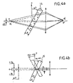
- the incident beam is oriented along the OZ axis, and directed along OZ.
- ⁇ Y represents the lateral offset of the images corresponding to the two orientations of the blade, separated by an angle of rotation ⁇ equal to 180 ° around its axis of rotation, which it is recalled that it is not confused with the any of the normal to the blade, and which for simplification is in the figures described confused with the axis OZ, we obtain:
- transparent LCD an LCD screen allowing the entire spectrum to pass visible.
- the invention further relates to a method and a device for transferring a digital image for acquisition by an installation using a CCD camera, that is to say integrating a charge transfer circuit.
- Figure 1 is as already indicated, a schematic representation of the exposure line of a traditional printer.
- Figure 2 is a schematic representation of an LCD pixel.
- Figure 3 illustrates a schematic representation of the transformation of the initial image to be restored, and in particular the distribution of the original image digital.
- Figures 4a and 4b illustrate the spatial offset of an incident beam generated by a blade with parallel faces.
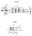
- Figure 5 is a schematic representation of the line of exposure of a printer according to the invention.
- Figure 6 is a representation of the orientation of the face blade parallel.
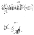
- Figure 7 is a schematic representation of the line of exposure an improved printer according to the invention.
- Figure 8 illustrates the principle of pixel resizing implemented in the installation of figure 7.
- Figure 9 is a schematic representation of the acquisition line of a CCD camera according to the method implemented in the invention.
- Figure 10 is a schematic representation of the line of exposure of a projector implementing the method of the invention.
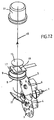
- Figure 11 is a schematic representation of an embodiment of the pixel multiplier device of the exposure line of a printer conforming to the invention.
- Figure 12 is a schematic representation of an embodiment of the line exposure optics integrating the blade with parallel faces according to FIG. 11.
- the invention cannot be limited to this only application, and that in particular, it can be implemented within the framework of image acquisition through CCD cameras, i.e. camera to device charge transfer and other image projection devices.
- the film holder (10) of this printer is replaced by an assembly consisting of an LCD screen (16), for example constituted by a panel marketed by the company SONY under the reference LCX017AL, comprising a matrix of 1024 x 768 active pixels, and at level from which an image stored in form can be reproduced digital, preceded by a linear polarizer (17) necessary for the operation of said LCD screen, intended to polarize the light coming from the beam incident according to a specific direction.
- an LCD screen for example constituted by a panel marketed by the company SONY under the reference LCX017AL, comprising a matrix of 1024 x 768 active pixels, and at level from which an image stored in form can be reproduced digital, preceded by a linear polarizer (17) necessary for the operation of said LCD screen, intended to polarize the light coming from the beam incident according to a specific direction.
- a linear polarizer (17) necessary for the operation of said LCD screen, intended to polarize the light coming from the beam incident according to a
- This blade with parallel faces (15) has an inclination at an angle ⁇ about 1 to 2 ° from the plane perpendicular to the axis of rotation of the blade, that is to say a plane perpendicular to the optical axis (18).
- this axis of rotation is parallel to the optical axis OZ, but this characteristic is not mandatory.
- the axis of rotation of the blade is in no way confused with any of the normals to said blade. In this way, during the rotation of the blade around its axis of rotation, the angle of inclination is oriented in the direction of the angle of rotation ⁇ , as described in connection with FIGS. 4b and 6 by compared to the OZ standard.
- This rotation induces a lateral (or polar) shift of the image in the plane (OX, OY), oriented in the direction of rotation ⁇ .
- the positions of the images shifted laterally trace a circular trajectory in the plane perpendicular to the optical axis.
- corresponding offset images can be obtained by as needed.
- This blade is for example made of transparent optical glass, and is capable of rotating relative to the optical axis (18), under the action of a motor electric (19) (figure 11).
- FIG. 3 shows a simplified explanation of the process implemented.
- the reference (23) represents the image original digital image obtained and stored at a resolution of 2048 x 1536 pixels within a memory associated with a central control and processing unit (not shown). This image is represented centered along the optical axis (18) of installation. Of course, within this installation, the original image does not appear not at the location shown, but is stored in digital memory. She was only shown here only for convenience of reasoning.
- This original image undergoes, if necessary, at the level of the central unit, a resizing in 2048 x 1536 pixels, that is to say exactly in four times more pixels than the number of pixels available at the level of the LCD screen ( 16). Furthermore, within this same central unit, this image thus resized is divided into four frames of 1024 x 768 pixels. Have thus been materialized in FIG. 3, these four frames (A 1 , B 1 , C 1 , ....), (A 2 , B 2 , C 2 , ....), (A 3 , B 3 , C 3 , ....), (A 4 , B 4 , C 4 , .7) in the form of a small square referenced 1, 2, 3, 4.
- the pixels of the LCD screen have been referenced in FIG. 3 by the letters A, B, C., etc.
- the blade with parallel faces (15) is oriented at an angle ⁇ of 45 °.
- the display on the LCD is of a first frame of pixels of the original image (23) referenced 1, ie A 1 , B 1 , C 1 , etc. We therefore have an image on the LCD comprising 1024 x 768 pixels.
- This image is exposed by the incident beam on the photosensitive paper (12).
- the blade (15) is oriented at an angle ⁇ of 135 °.
- the blade (15) is oriented at an angle ⁇ of 225 °, and the projection and exposure operation is repeated on the same sheet of photosensitive paper, this time only the pixels of the original image (23) referenced 3, i.e. A 3 , B 3 , C 3 , etc.
- the blade (15) is oriented at an angle ⁇ of 315 °, and the projection and exposure operation is repeated on the same sheet of photosensitive paper, this time only the pixels of the original image (23) referenced 4, i.e. A 4 , B 4 , C 4 , etc.
- each pixel of an LCD has a optically active zone (13) and an optically inactive zone (14).
- optically active zone (13) the exposure of each of the LCD pixels.
- these overexposures are invisible to the naked eye for small formats (for example 10 x 15).
- the original image (23) is divided into two only pixel frames.
- the method described above remains exactly the same, but this time we only do two exposures, performing a single blade rotation between the two exposures (15).
- the values of ⁇ are then determined according to the overlap of the pixel optimal. In this case, the resolution of the LCD is significantly multiplied by 2.
- the original image is not divided into frames. It is therefore displayed after resizing as is on the LCD screen (16). For each exposure of the LCD screen, we subject the blade with parallel faces (15) sufficient continuous rotation about its axis of rotation (18). During this or these rotations, the shutter (3) remains open.
- This embodiment is therefore only applicable in conjunction with the multiplication of the pixels of the LCD, therefore within the framework of the division of the image initial in four frames.
- the image displayed on the LCD (16) is projected by a lens (26) on a pixel mask (24), intended to resize the image of the active area (13) of the LCD pixel, in particular according to a square shape.
- This resized image passes through a field lens (25), intended to make the beam converge at the projection objective (11).
- a field lens 25
- the blade with parallel faces (15) previously described is interposed between the lens (25) and said objective, interposed the blade with parallel faces (15) previously described.
- the grid (24) is for example constituted by a glass plate receiving a emulsion distributed in such a way as to allow only 25% of the pixel surface to pass LCD.
- FIG. 8 shows the image (27) of said pixel after passing through the objective (26). We see in (28) the 25% who were able to cross the system. (29) represents the border between the active area and the inactive area of the LCD pixel.
- the source light (1) is oriented 90 ° to the optical axis (18), but a mirror with 45 ° (22) allows the incident beam to be redirected.
- FIG. 12 shows the electric motor (19) ensuring the rotation of the blade (15), by means of a toothed belt (20) which meshes in a crown (21) shaped accordingly, at said module.
- the same general principle of the invention can also be implemented as part of the acquisition of optical signals during the implementation of CCD camera. Basically shown in connection with Figure 9, the line optical acquisition of these signals.
- the object (30) to be acquired is located on the route optics of a CCD camera (32). Between the two, are successively positioned a projection objective (31) and the blade with parallel faces (15) conforming to the invention.
- Optical signals are shifted at the CCD, so we can multiply the resolution or definition of it according to the same principle as that described above.
- the invention also relates to an image projector highlighting implements the process of the invention.
- a light source 33
- This comprises a light source (33), split into three components, red, green and blue by means of devices appropriate.
- Each of these three components crosses a whole (35, 36, 37) consisting of a linear polarizer and an LCD, at which are displayed digital images, the same at the three LCDs, the emerging beams of these assemblies being recombined at the level of an organ (38) known for this application.
- the resulting beam passes through a parallel-faced blade (15) of the type of that previously described, rotating continuously at high speed, typically 24 revolutions per second, before passing through a projection objective (39), to reach the viewing plane (40).
- this offset can be an odd multiple of half a pixel, and in particular, 3/2 pixels, 5/2 pixels, etc. .
- the use of a larger lag can lead to a better homogeneity in the restored print.
Landscapes
- Physics & Mathematics (AREA)
- General Physics & Mathematics (AREA)
- Engineering & Computer Science (AREA)
- Multimedia (AREA)
- Signal Processing (AREA)
- Liquid Crystal (AREA)
- Projection-Type Copiers In General (AREA)
- Eye Examination Apparatus (AREA)
- Apparatus For Radiation Diagnosis (AREA)
Claims (12)
- Verfahren zur visuellen Wiedergabe eines digitalen Bildes, welches auf einem transparenten LCD-Flüssigkristall-Bildschirm angezeigt wird, gekennzeichnet durch:Bilden des auf dem LCD angezeigten Bildes auf dem visuellen Wiedergabeträger und insbesondere auf einem photosensiblen Papier mittels eines Projektionsobjektivs;Bewirken mittels eines einzigen optischen Organs mindestens einer seitlichen Verschiebung in der Projektionsebene jedes der Pixel des auf dem LCD angezeigten Bildes,und Durchführung einer oder mehrerer Belichtungen im Bereich des genannten visuellen Wiedergabeträgers für jede dieser Verschiebungen.
- Verfahren zur Erfassung eines digitalen Bildes auf dem ladungsgekoppelten CCD-Bauelement einer Kamera, gekennzeichnet durch:Bilden des Bildes eines Gegenstandes auf dem CCD mittels eines Aufnahmeobjektivs;Bewirken mittels eines einzigen optischen Organs mindestens einer seitlichen Verschiebung in der Aufnahmeebene des auf dem CCD gebildeten Bildes,und Durchführen einer oder mehrerer Aufnahmen im Bereich des genannten CCDs für jede dieser Verschiebungen.
- Verfahren nach Anspruch 1, dadurch gekennzeichnet, daß eine einzige Belichtung des auf dem LCD angezeigten Bildes durchgeführt wird und daß jedes der Pixel des genannten Bildes einer kontinuierlichen Verschiebung entlang einer kreisförmigen Bahn in der Belichtungsebene unterworfen wird, wobei die Verschiebung jedes der Pixel in bezug auf das betroffene Pixel zentriert ist.
- Verfahren nach Anspruch 1, dadurch gekennzeichnet, daß:eine Redimensionierung des wiederzugebenden digitalen Bildes durchgeführt wird;das genannte Bild in zwei auf dem LCD anzeigbare Raster aufgeteilt wird;und für jedes Raster des auf dem LCD angezeigten Bildes eine Belichtung vorgenommen wird, indem zwischen den beiden Belichtungen eine diskrete Verschiebung der Gesamtheit der Pixel des auf dem LCD angezeigten Bildes gemäß den Orientierungsrichtungen OX und OY der genannten Pixel symmetrisch in bezug auf die Mitte jedes einzelnen der Pixel bewirkt wird.
- Verfahren nach Anspruch 1, dadurch gekennzeichnet, daß:eine Redimensionierung des wiederzugebenden digitalen Bildes durchgeführt wird;das genannte Bild in vier auf dem LCD anzeigbare Raster aufgeteilt wird;und für jedes Raster des auf dem LCD angezeigten Bildes eine Belichtung vorgenommen wird, indem zwischen jeder der vier Belichtungen eine diskrete Verschiebung der Gesamtheit der Pixel des auf dem LCD angezeigten Bildes gemäß den Orientierungsrichtungen OX und OY der genannten Pixel symmetrisch in bezug auf die Achsen OX und OY der Pixel bewirkt wird.
- Verfahren nach einem der Ansprüche 4 und 5, dadurch gekennzeichnet, daß jedes Raster drei Bildebenen aufweist, entsprechend den drei Farben rot, grün und blau, wobei die resultierenden Bilder entsprechend dem Verfahren der additiven Farbmischung farbig sind.
- Vorrichtung zur visuellen Wiedergabe eines oder mehrerer digitaler Bilder, welche auf einem transparenten LCD-Bildschirm (16) angezeigt sind, dadurch gekennzeichnet, daß sie folgendes umfaßt:eine Lichtquelle (1), auf deren optischer Bahn der genannte LCD-Bildschirm (16) angeordnet ist, auf dem die digitalen Bilder insbesondere durch eine Zentraleinheit angezeigt sind,einen Verschluß (3), der dazu bestimmt ist, den Lichtstrahl bei Bedarf zu verschließen;ein Projektionsobjektiv (11), welches zwischen dem LCD-Bildschirm (16) und dem zu belichtenden Papier (12) angeordnet ist;einen linearen Polarisationsfilter (17), der zwischen der Lichtquelle (1) und dem LCD-Bildschirm angeordnet ist;eine einzige Platte (15) mit parallelen Flächen und konstanter Dicke, welche für das Spektrum des verwendeten Lichtes transparent ist und auf der optischen Bahn OZ der Quelle zwischen dem LCD-Bildschirm (16) und dem Projektionsobjektiv (11) angeordnet ist, wobei die genannte Platte mit parallelen Flächen dazu geeignet ist, zu einer diskreten oder kontinuierlichen Rotationsbewegung angetrieben zu werden, deren Rotationsachse parallel oder nicht parallel zur optischen Achse ist, wobei die genannte Platte (15) um einen festen Winkel α in bezug auf die zu ihrer Rotationsachse rechtwinklige Ebene geneigt ist.
- Vorrichtung nach Anspruch 7, dadurch gekennzeichnet, daß sie ferner einen motorisierten (6) Objektivrevolver (5) aufweist, welcher im Hinblick auf die Herstellung von Farbfotos Filter, nämlich einen roten, grünen und blauen, trägt.
- Vorrichtung nach einem der Ansprüche 7 und 8, dadurch gekennzeichnet, daß die Rotation der Platte mit parallelen Flächen (15) mittels eines elektrischen Motors erfolgt.
- Vorrichtung nach Anspruch 7, dadurch gekennzeichnet, daß sie weiterhin folgendes umfaßt:wobei die genannten Platte (15) mit parallelen Flächen auf der optischen Bahn OZ der Quelle zwischen der Feldlinse (25) und dem Projektionsobjektiv (11) angeordnet ist.eine hinter dem LCD-Bildschirm (16) befindliche Blende (24), welche dazu bestimmt ist, nur einen Teil der aktiven Zone (13) jedes der LCD-Pixel auszuwählen;ein Projektionsobjektiv (26), welches dazu bestimmt ist, auf der Blende (24) das auf dem LCD angezeigte Bild anzuzeigen;eine Feldlinse (25), welche dazu bestimmt ist, den von der Blende (24) ausgehenden Lichtstrahl im Bereich des Projektionsobjektivs (11) zu konvergieren;
- Vorrichtung zur Aufnahme eines digitalen Bildes auf dem ladungsgekoppelten CCD-Bauelement einer Kamera, dadurch gekennzeichnet, daß sie folgendes umfaßt:ein Aufnahmeobjektiv (31), welches zwischen der CCD-Kamera (32) und dem Gegenstand oder Objekt (30) angeordnet ist, von dem eine digitale Bildaufnahme erwünscht ist;eine einzige Platte (15) mit parallelen Flächen und konstanter Dicke, welche für das Spektrum des verwendeten Lichtes transparent ist und auf der optischen Bahn zwischen der CCD-Kamera und dem Aufnahmeobjektiv angeordnet ist, wobei die genannte Platte mit parallelen Flächen dazu geeignet ist, zu einer diskreten Rotationsbewegung angetrieben zu werden, deren Rotationsachse parallel oder nicht parallel zur optischen Achse verläuft, wobei die genannte Platte in einem festen Winkel α in bezug auf die rechtwinklig zu ihrer Rotationsachse verlaufende Ebene geneigt ist.
- Vorrichtung zur Projektion eines digitalen Bildes, insbesondere auf einen Bildschirm, mit dem Ziel seiner visuellen Wiedergabe, dadurch gekennzeichnet, daß sie folgendes umfaßt:wobei die genannte Platte (15) um einen festen Winkel α in bezug auf die zu ihrer Rotationsachse rechtwinklige Ebene geneigt ist.eine Lichtquelle (33),ein Mittel zum Auftrennen des einfallenden, von der Lichtquelle ausgehenden Strahles in drei diskrete Strahlen, welche den drei Grundfarben rot, grün und blau entsprechen, wobei auf der optischen Bahn jeder dieser Strahlen ein linearer Polarisationsfilter und ein transparenter, monochromer LCD-Bildschirm angeordnet sind, wobei jeder der drei LCD gleichzeitig das gleiche digitale Bild anzeigt, insbesondere unter Verwendung einer Zentraleinheit,ein Organ (38) zur Zusammenführung der von jedem der drei LCDs ausgehenden Signale;ein Projektionsobjektiv (39), welches zwischen dem Zusammenführungsorgan und dem Bildschirm (40) angeordnet ist, um das projizierte Bild aufzunehmen;eine einzige Platte (15) mit parallelen Flächen und konstanter Dicke, welche für das Spektrum des verwendeten Lichtes transparent ist und auf der optischen Bahn zwischen dem Zusammenführungsorgan und dem Projektionsobjektiv angeordnet ist, wobei die genannte Platte mit parallelen Flächen zu einer kontinuierlichen Rotationsbewegung angetrieben wird, deren Rotationsachse parallel oder nicht parallel zur optischen Achse ist,
Applications Claiming Priority (2)
| Application Number | Priority Date | Filing Date | Title |
|---|---|---|---|
| FR9811648A FR2783387B1 (fr) | 1998-09-15 | 1998-09-15 | Procede perfectionne pour transferer une image numerique en vue de sa restitution visuelle ou de son acquisition et dispositifs pour la mise en oeuvre de ce procede |
| FR9811648 | 1998-09-15 |
Publications (2)
| Publication Number | Publication Date |
|---|---|
| EP0987875A1 EP0987875A1 (de) | 2000-03-22 |
| EP0987875B1 true EP0987875B1 (de) | 2002-08-07 |
Family
ID=9530564
Family Applications (1)
| Application Number | Title | Priority Date | Filing Date |
|---|---|---|---|
| EP99420189A Expired - Lifetime EP0987875B1 (de) | 1998-09-15 | 1999-09-09 | Verfahren und Gerät zum Darstellen eines digitalen Bildes oder Erfassung desselben |
Country Status (5)
| Country | Link |
|---|---|
| EP (1) | EP0987875B1 (de) |
| JP (1) | JP3576882B2 (de) |
| AT (1) | ATE222037T1 (de) |
| DE (1) | DE69902428D1 (de) |
| FR (1) | FR2783387B1 (de) |
Cited By (1)
| Publication number | Priority date | Publication date | Assignee | Title |
|---|---|---|---|---|
| US6867847B2 (en) | 2002-07-11 | 2005-03-15 | Agfa-Gevaert Aktiengesellschaft | Apparatus and method for projecting graphic information onto a light-sensitive material |
Families Citing this family (10)
| Publication number | Priority date | Publication date | Assignee | Title |
|---|---|---|---|---|
| ITPN20010084A1 (it) * | 2001-11-29 | 2003-05-29 | Gpe Srl | Dispositivo di controllo adattabile a qualsiasi genere di laboratoriodi sviluppo e stampa di tipo professionale e/o amatoriale di fotografi |
| FR2836238B1 (fr) * | 2002-02-19 | 2004-04-02 | Kis | Procede pour transferer une image numerique en vue de sa restitution visuelle, et dispositif pour la mise en oeuvre de ce procede |
| EP1345406A1 (de) * | 2002-03-12 | 2003-09-17 | Agfa-Gevaert AG | Verfahren und Vorrichtung zum Aufbelichten von in einzelne Pixel aufgeteilten Bildinformationen auf lichtempfindliches Material |
| US7034811B2 (en) | 2002-08-07 | 2006-04-25 | Hewlett-Packard Development Company, L.P. | Image display system and method |
| JP4390189B2 (ja) * | 2003-04-10 | 2009-12-24 | 大日本スクリーン製造株式会社 | パターン描画装置 |
| ITUD20030114A1 (it) * | 2003-05-28 | 2004-11-29 | Gpe Srl | Dispositivo per effettuare microspostamenti di un supporto di immagini digitali. |
| EP1492325A1 (de) * | 2003-06-24 | 2004-12-29 | Agfa-Gevaert AG | Vorrichtung und Verfahren zum Aufbelichten von in einzelne Pixel aufgeteilten Bildinformationen auf lichtempfindliches Material |
| FR2897167B1 (fr) * | 2006-02-08 | 2008-08-08 | Kis Soc Par Actions Simplifiee | Dispositif et procede d'eclairage pour exposer un support d'enregistrement photosensible, et installation poour le tirage automatique de photographies mettant en oeuvre un tel dispositif |
| DE102008022253A1 (de) * | 2008-05-06 | 2009-11-12 | Miva Technologies Gmbh | Hochauflösendes Fotoplottverfahren und Anordnung zur hochauflösenden Aufzeichnung eines computergespeicherten Rasterbildes auf einen ebenen lichtempfindlichen Aufzeichnungsträger |
| FR2935813B1 (fr) | 2008-09-11 | 2010-10-08 | Kis | Installation pour l'exposition d'un film cinematographique a partir d'images numeriques |
Family Cites Families (3)
| Publication number | Priority date | Publication date | Assignee | Title |
|---|---|---|---|---|
| WO1986005642A1 (en) * | 1985-03-11 | 1986-09-25 | Eastman Kodak Company | Apparatus for scanning and sampling real images |
| DE9109236U1 (de) * | 1991-07-26 | 1991-09-19 | Kodak Ag, 7000 Stuttgart | Vorrichtung zum Strahlenversetzen |
| GB2299476B (en) * | 1995-03-28 | 1999-06-23 | Integrex Ltd | Electronic printing method and apparatus |
-
1998
- 1998-09-15 FR FR9811648A patent/FR2783387B1/fr not_active Expired - Fee Related
-
1999
- 1999-09-09 DE DE69902428T patent/DE69902428D1/de not_active Expired - Lifetime
- 1999-09-09 EP EP99420189A patent/EP0987875B1/de not_active Expired - Lifetime
- 1999-09-09 AT AT99420189T patent/ATE222037T1/de not_active IP Right Cessation
- 1999-09-14 JP JP26094399A patent/JP3576882B2/ja not_active Expired - Fee Related
Cited By (1)
| Publication number | Priority date | Publication date | Assignee | Title |
|---|---|---|---|---|
| US6867847B2 (en) | 2002-07-11 | 2005-03-15 | Agfa-Gevaert Aktiengesellschaft | Apparatus and method for projecting graphic information onto a light-sensitive material |
Also Published As
| Publication number | Publication date |
|---|---|
| FR2783387A1 (fr) | 2000-03-17 |
| JP2000147677A (ja) | 2000-05-26 |
| FR2783387B1 (fr) | 2000-10-13 |
| JP3576882B2 (ja) | 2004-10-13 |
| ATE222037T1 (de) | 2002-08-15 |
| DE69902428D1 (de) | 2002-09-12 |
| EP0987875A1 (de) | 2000-03-22 |
Similar Documents
| Publication | Publication Date | Title |
|---|---|---|
| EP0256051B1 (de) | Bildverarbeitungsvorrichtung zur kontrolle der transferfunktion eines optischen systems | |
| CH621634A5 (de) | ||
| WO2008062129A1 (fr) | Agencement d'affichage opto-electronique | |
| FR2569481A1 (fr) | Systeme d'enregistrement de teintes continues | |
| FR2459496A2 (fr) | Appareil photographique rapporte pour microscopes | |
| EP0987875A1 (de) | Verfahren und Gerät zum Darstellen eines digitalen Bildes oder Erfassung desselben | |
| EP1763962B1 (de) | Digitaler bildprojektor mit grossbildschirm | |
| EP1477019B1 (de) | Verfahren zum transferieren eines digitalen bildes, um so das digitale bild visuell wiederherzustellen, und einrichtung zur ausführung des verfahrens | |
| FR2800163A1 (fr) | Dispositif de mesure de la repartition spatiale de l'emission spectrale d'un objet | |
| FR2819101A1 (fr) | Capteur photosensible en technologie des circuits integres | |
| FR2576473A1 (fr) | Systeme optique de balayage lumineux d'un explorateur de sortie d'image utilisant un modulateur electromecanique de lumiere | |
| FR2593616A1 (fr) | Bague avec obturateur integre, en particulier pour prise de vues | |
| CA2161709C (en) | Image reading device for photographic printing | |
| EP4202544A1 (de) | Doppelvisier für beobachtungsvorrichtung | |
| CA1263761A (fr) | Dispositif de traitement d'image pour le controle de la fonction de transfert d'un systeme optique | |
| EP3982188B1 (de) | Virtual-reality- oder augmented-reality-sichtsystem mit bildsensor des auges | |
| EP2164241B1 (de) | Anlage zumBelichten Vorführen eines Kinofilms auf der Grundlage von Digitalbildern | |
| FR2705795A1 (fr) | Dispositif miniaturisé de visualisation d'image d'objets mobiles, en particulier pour simulateur à écran sphérique de faibles dimensions. | |
| EP0026129A1 (de) | Vorrichtung zur Farbbildprojektion auf einen Bildschirm und Anzeigesystem mit einer solchen Vorrichtung | |
| FR2627042A1 (fr) | Dispositif de prise de vue d'images fixes de haute definition | |
| FR3053807A1 (fr) | Dispositif et procede de photolithographie | |
| WO2025133476A1 (fr) | Dispositif d'imagerie a forte distorsion geometrique | |
| FR2854959A1 (fr) | Dispositif d'exposition pour l'ecriture de donnees mixtes sur un support photosensible | |
| FR2630835A1 (fr) | Procede de realisation d'images en relief et moyens pour mettre en oeuvre ledit procede | |
| FR2977946A1 (fr) | Obturateur pour camera numerique |
Legal Events
| Date | Code | Title | Description |
|---|---|---|---|
| PUAI | Public reference made under article 153(3) epc to a published international application that has entered the european phase |
Free format text: ORIGINAL CODE: 0009012 |
|
| AK | Designated contracting states |
Kind code of ref document: A1 Designated state(s): AT BE CH CY DE DK ES FI FR GB GR IE IT LI LU MC NL PT SE |
|
| AX | Request for extension of the european patent |
Free format text: AL;LT;LV;MK;RO;SI |
|
| 17P | Request for examination filed |
Effective date: 20000427 |
|
| AKX | Designation fees paid |
Free format text: AT BE CH CY DE DK ES FI FR GB GR IE IT LI LU MC NL PT SE |
|
| 17Q | First examination report despatched |
Effective date: 20011126 |
|
| GRAG | Despatch of communication of intention to grant |
Free format text: ORIGINAL CODE: EPIDOS AGRA |
|
| GRAG | Despatch of communication of intention to grant |
Free format text: ORIGINAL CODE: EPIDOS AGRA |
|
| GRAH | Despatch of communication of intention to grant a patent |
Free format text: ORIGINAL CODE: EPIDOS IGRA |
|
| GRAH | Despatch of communication of intention to grant a patent |
Free format text: ORIGINAL CODE: EPIDOS IGRA |
|
| GRAA | (expected) grant |
Free format text: ORIGINAL CODE: 0009210 |
|
| AK | Designated contracting states |
Kind code of ref document: B1 Designated state(s): AT BE CH CY DE DK ES FI FR GB GR IE IT LI LU MC NL PT SE |
|
| PG25 | Lapsed in a contracting state [announced via postgrant information from national office to epo] |
Ref country code: NL Free format text: LAPSE BECAUSE OF FAILURE TO SUBMIT A TRANSLATION OF THE DESCRIPTION OR TO PAY THE FEE WITHIN THE PRESCRIBED TIME-LIMIT Effective date: 20020807 Ref country code: IT Free format text: LAPSE BECAUSE OF FAILURE TO SUBMIT A TRANSLATION OF THE DESCRIPTION OR TO PAY THE FEE WITHIN THE PRE;WARNING: LAPSES OF ITALIAN PATENTS WITH EFFECTIVE DATE BEFORE 2007 MAY HAVE OCCURRED AT ANY TIME BEFORE 2007. THE CORRECT EFFECTIVE DATE MAY BE DIFFERENT FROM THE ONE RECORDED.SCRIBED TIME-LIMIT Effective date: 20020807 Ref country code: IE Free format text: LAPSE BECAUSE OF FAILURE TO SUBMIT A TRANSLATION OF THE DESCRIPTION OR TO PAY THE FEE WITHIN THE PRESCRIBED TIME-LIMIT Effective date: 20020807 Ref country code: GR Free format text: LAPSE BECAUSE OF FAILURE TO SUBMIT A TRANSLATION OF THE DESCRIPTION OR TO PAY THE FEE WITHIN THE PRESCRIBED TIME-LIMIT Effective date: 20020807 Ref country code: FI Free format text: LAPSE BECAUSE OF FAILURE TO SUBMIT A TRANSLATION OF THE DESCRIPTION OR TO PAY THE FEE WITHIN THE PRESCRIBED TIME-LIMIT Effective date: 20020807 Ref country code: AT Free format text: LAPSE BECAUSE OF FAILURE TO SUBMIT A TRANSLATION OF THE DESCRIPTION OR TO PAY THE FEE WITHIN THE PRESCRIBED TIME-LIMIT Effective date: 20020807 |
|
| REF | Corresponds to: |
Ref document number: 222037 Country of ref document: AT Date of ref document: 20020815 Kind code of ref document: T |
|
| REG | Reference to a national code |
Ref country code: GB Ref legal event code: FG4D Free format text: NOT ENGLISH |
|
| REG | Reference to a national code |
Ref country code: CH Ref legal event code: EP |
|
| REG | Reference to a national code |
Ref country code: IE Ref legal event code: FG4D Free format text: FRENCH |
|
| PG25 | Lapsed in a contracting state [announced via postgrant information from national office to epo] |
Ref country code: LU Free format text: LAPSE BECAUSE OF NON-PAYMENT OF DUE FEES Effective date: 20020909 |
|
| REF | Corresponds to: |
Ref document number: 69902428 Country of ref document: DE Date of ref document: 20020912 |
|
| PG25 | Lapsed in a contracting state [announced via postgrant information from national office to epo] |
Ref country code: CY Free format text: LAPSE BECAUSE OF FAILURE TO SUBMIT A TRANSLATION OF THE DESCRIPTION OR TO PAY THE FEE WITHIN THE PRESCRIBED TIME-LIMIT Effective date: 20020930 Ref country code: BE Free format text: LAPSE BECAUSE OF NON-PAYMENT OF DUE FEES Effective date: 20020930 |
|
| GBT | Gb: translation of ep patent filed (gb section 77(6)(a)/1977) |
Effective date: 20020916 |
|
| PG25 | Lapsed in a contracting state [announced via postgrant information from national office to epo] |
Ref country code: SE Free format text: LAPSE BECAUSE OF FAILURE TO SUBMIT A TRANSLATION OF THE DESCRIPTION OR TO PAY THE FEE WITHIN THE PRESCRIBED TIME-LIMIT Effective date: 20021107 Ref country code: DK Free format text: LAPSE BECAUSE OF FAILURE TO SUBMIT A TRANSLATION OF THE DESCRIPTION OR TO PAY THE FEE WITHIN THE PRESCRIBED TIME-LIMIT Effective date: 20021107 |
|
| PG25 | Lapsed in a contracting state [announced via postgrant information from national office to epo] |
Ref country code: DE Free format text: LAPSE BECAUSE OF FAILURE TO SUBMIT A TRANSLATION OF THE DESCRIPTION OR TO PAY THE FEE WITHIN THE PRESCRIBED TIME-LIMIT Effective date: 20021108 |
|
| PG25 | Lapsed in a contracting state [announced via postgrant information from national office to epo] |
Ref country code: PT Free format text: LAPSE BECAUSE OF FAILURE TO SUBMIT A TRANSLATION OF THE DESCRIPTION OR TO PAY THE FEE WITHIN THE PRESCRIBED TIME-LIMIT Effective date: 20021122 |
|
| NLV1 | Nl: lapsed or annulled due to failure to fulfill the requirements of art. 29p and 29m of the patents act | ||
| PG25 | Lapsed in a contracting state [announced via postgrant information from national office to epo] |
Ref country code: ES Free format text: LAPSE BECAUSE OF FAILURE TO SUBMIT A TRANSLATION OF THE DESCRIPTION OR TO PAY THE FEE WITHIN THE PRESCRIBED TIME-LIMIT Effective date: 20030228 |
|
| BERE | Be: lapsed |
Owner name: *KIS Effective date: 20020930 |
|
| PG25 | Lapsed in a contracting state [announced via postgrant information from national office to epo] |
Ref country code: MC Free format text: LAPSE BECAUSE OF NON-PAYMENT OF DUE FEES Effective date: 20030401 |
|
| REG | Reference to a national code |
Ref country code: IE Ref legal event code: FD4D Ref document number: 0987875E Country of ref document: IE |
|
| PLBE | No opposition filed within time limit |
Free format text: ORIGINAL CODE: 0009261 |
|
| STAA | Information on the status of an ep patent application or granted ep patent |
Free format text: STATUS: NO OPPOSITION FILED WITHIN TIME LIMIT |
|
| 26N | No opposition filed |
Effective date: 20030508 |
|
| PG25 | Lapsed in a contracting state [announced via postgrant information from national office to epo] |
Ref country code: LI Free format text: LAPSE BECAUSE OF NON-PAYMENT OF DUE FEES Effective date: 20030930 Ref country code: CH Free format text: LAPSE BECAUSE OF NON-PAYMENT OF DUE FEES Effective date: 20030930 |
|
| REG | Reference to a national code |
Ref country code: CH Ref legal event code: PL |
|
| PGFP | Annual fee paid to national office [announced via postgrant information from national office to epo] |
Ref country code: GB Payment date: 20040827 Year of fee payment: 6 |
|
| PGFP | Annual fee paid to national office [announced via postgrant information from national office to epo] |
Ref country code: FR Payment date: 20040930 Year of fee payment: 6 |
|
| PG25 | Lapsed in a contracting state [announced via postgrant information from national office to epo] |
Ref country code: GB Free format text: LAPSE BECAUSE OF NON-PAYMENT OF DUE FEES Effective date: 20050909 |
|
| GBPC | Gb: european patent ceased through non-payment of renewal fee |
Effective date: 20050909 |
|
| PG25 | Lapsed in a contracting state [announced via postgrant information from national office to epo] |
Ref country code: FR Free format text: LAPSE BECAUSE OF NON-PAYMENT OF DUE FEES Effective date: 20060531 |
|
| REG | Reference to a national code |
Ref country code: FR Ref legal event code: ST Effective date: 20060531 |