EP0987963B1 - Kugel- und stichschutzjacke - Google Patents
Kugel- und stichschutzjacke Download PDFInfo
- Publication number
- EP0987963B1 EP0987963B1 EP98932204A EP98932204A EP0987963B1 EP 0987963 B1 EP0987963 B1 EP 0987963B1 EP 98932204 A EP98932204 A EP 98932204A EP 98932204 A EP98932204 A EP 98932204A EP 0987963 B1 EP0987963 B1 EP 0987963B1
- Authority
- EP
- European Patent Office
- Prior art keywords
- protective
- assembly according
- assembly
- plate
- protection
- Prior art date
- Legal status (The legal status is an assumption and is not a legal conclusion. Google has not performed a legal analysis and makes no representation as to the accuracy of the status listed.)
- Expired - Lifetime
Links
- 230000001681 protective effect Effects 0.000 claims abstract description 80
- 239000006260 foam Substances 0.000 claims description 32
- 239000004744 fabric Substances 0.000 claims description 15
- 210000001015 abdomen Anatomy 0.000 claims description 13
- 229920003235 aromatic polyamide Polymers 0.000 claims description 10
- 239000004760 aramid Substances 0.000 claims description 9
- 230000035939 shock Effects 0.000 claims description 6
- 229920001971 elastomer Polymers 0.000 claims description 5
- 239000000806 elastomer Substances 0.000 claims description 4
- 210000002784 stomach Anatomy 0.000 claims 2
- 210000000056 organ Anatomy 0.000 description 15
- 210000000038 chest Anatomy 0.000 description 12
- 241000531908 Aramides Species 0.000 description 8
- 208000014674 injury Diseases 0.000 description 7
- 210000000115 thoracic cavity Anatomy 0.000 description 7
- 239000000463 material Substances 0.000 description 5
- 241000195940 Bryophyta Species 0.000 description 4
- 235000011929 mousse Nutrition 0.000 description 4
- 239000004033 plastic Substances 0.000 description 4
- 229920003023 plastic Polymers 0.000 description 4
- -1 polypropylene Polymers 0.000 description 4
- 229920000271 Kevlar® Polymers 0.000 description 3
- 230000000712 assembly Effects 0.000 description 3
- 238000000429 assembly Methods 0.000 description 3
- 230000001413 cellular effect Effects 0.000 description 3
- 210000001519 tissue Anatomy 0.000 description 3
- 208000031968 Cadaver Diseases 0.000 description 2
- 229920003368 Kevlar® 29 Polymers 0.000 description 2
- 239000004743 Polypropylene Substances 0.000 description 2
- 238000010009 beating Methods 0.000 description 2
- 238000005452 bending Methods 0.000 description 2
- 229920001821 foam rubber Polymers 0.000 description 2
- 239000003365 glass fiber Substances 0.000 description 2
- 229920001155 polypropylene Polymers 0.000 description 2
- 206010016334 Feeling hot Diseases 0.000 description 1
- RRHGJUQNOFWUDK-UHFFFAOYSA-N Isoprene Chemical compound CC(=C)C=C RRHGJUQNOFWUDK-UHFFFAOYSA-N 0.000 description 1
- 239000004698 Polyethylene Substances 0.000 description 1
- 206010041899 Stab wound Diseases 0.000 description 1
- 230000004308 accommodation Effects 0.000 description 1
- 239000000853 adhesive Substances 0.000 description 1
- 230000001070 adhesive effect Effects 0.000 description 1
- 239000000919 ceramic Substances 0.000 description 1
- 230000001419 dependent effect Effects 0.000 description 1
- 238000009792 diffusion process Methods 0.000 description 1
- 230000001788 irregular Effects 0.000 description 1
- 239000002184 metal Substances 0.000 description 1
- 230000000116 mitigating effect Effects 0.000 description 1
- 230000000149 penetrating effect Effects 0.000 description 1
- 230000035515 penetration Effects 0.000 description 1
- 229920000573 polyethylene Polymers 0.000 description 1
- 229920001195 polyisoprene Polymers 0.000 description 1
- 230000001012 protector Effects 0.000 description 1
- 239000011347 resin Substances 0.000 description 1
- 229920005989 resin Polymers 0.000 description 1
- 230000029058 respiratory gaseous exchange Effects 0.000 description 1
- 239000005060 rubber Substances 0.000 description 1
- 230000008733 trauma Effects 0.000 description 1
- 230000003144 traumatizing effect Effects 0.000 description 1
- 238000009423 ventilation Methods 0.000 description 1
- 235000012431 wafers Nutrition 0.000 description 1
Images


Classifications
-
- A—HUMAN NECESSITIES
- A41—WEARING APPAREL
- A41D—OUTERWEAR; PROTECTIVE GARMENTS; ACCESSORIES
- A41D13/00—Professional, industrial or sporting protective garments, e.g. surgeons' gowns or garments protecting against blows or punches
- A41D13/015—Professional, industrial or sporting protective garments, e.g. surgeons' gowns or garments protecting against blows or punches with shock-absorbing means
- A41D13/0153—Professional, industrial or sporting protective garments, e.g. surgeons' gowns or garments protecting against blows or punches with shock-absorbing means having hinged or separable parts
-
- F—MECHANICAL ENGINEERING; LIGHTING; HEATING; WEAPONS; BLASTING
- F41—WEAPONS
- F41H—ARMOUR; ARMOURED TURRETS; ARMOURED OR ARMED VEHICLES; MEANS OF ATTACK OR DEFENCE, e.g. CAMOUFLAGE, IN GENERAL
- F41H1/00—Personal protection gear
- F41H1/02—Armoured or projectile- or missile-resistant garments; Composite protection fabrics
Definitions
- the invention relates to protective devices for the human body and vests with such organs.
- Document DE-4 214 543 discloses a protection package according to the preamble of claim 1 of this application.
- a first object of the invention is to provide a protective device which can be adapted to suit wishes of the user, for example to be will either bulletproof or bulletproof, or even two at a time.
- a set of protection of the human body comprising an element of generally flat bumper protection and a protective body having a generally flat shape, comprising means for removable support of the element protective so the organ and the element are substantially parallel, in contact and facing one of the other, the member comprising a rigid plate, in which the rigid plate is permanently received in the organ.
- the protection body can at will receive or not receive one or more items protection according to the wishes of the user.
- This will for example be a bumper element and a bulletproof element.
- the support means include at least one pocket adapted to receive the protective element at least in part.
- the support means are formed. particularly simple way.
- the protection member comprises means to prohibit the exit of the element from pocket protection.
- the pocket is adapted to receive the entire protective element and includes pocket closing means.
- the pocket or pockets extend over a major part of the surface of the organ of protection.
- the protection member comprises at least two pockets at least partially not superimposed.
- each pocket is suitable for protection of this or that part of the body. So we have a protective element in one and / or the other of the pockets depending on the degree of protection and the bodily freedom desired.
- the protection body provides protection minimal when it lacks an element of protection.
- the organ comprises at least one foam board permanently attached to the body protection, and means for holding the plate rigid and the foam plate parallel to one the other and facing each other, the two plates being free to move relative to each other, the foam plate being arranged to extend between the rigid plate and the body.
- the organ thus alone provides protection minimal bumper while being comfortable to wear.
- the protection member comprises two foam plates between which the rigid plate.
- the rigid plate is unique and extends over most of the protective organ.
- the protection member is intended to protect at least one part of the body following: thorax, abdomen, lower abdomen, back, shoulder.
- a assembly comprising a protective member according to the invention and at least one suitable protective element to be removably supported by the protection.
- the assembly comprises at least two protective elements adapted to be supported simultaneously removably by the protection.
- the protective elements are adapted to be supported by being superimposed mutually in part.
- the protective elements are adapted to be supported by being received in the same protective organ pocket.
- the or each element of protection is suitable for warding gun bullets.
- a vest comprising at least one assembly according to the invention.
- the protective vest comprises at least two sets according to the invention (for example respectively for the back and the thorax), and means for removable fastening of the assemblies together, the means being adapted to allow adjustment of the relative position of the assemblies.
- the arrangement of the different parts of the vest on the user's body can be adapted in dependent on absence, presence, or number of protective elements attached to the organs of protection.
- a bulletproof vest comprising several layers of aramid such as kevlar®, superimposed.
- This type of vest has many disadvantages. They do not provide anti-trauma protection, that is, once the bullet protection against impact on the body due to the ball. In addition, they do not provide protection against beatings with a stabbed weapon or of a tool. Finally, they are not very comfortable: aramid layers do not remain in a stable position on the user's body and tend to slip. Of moreover, they considerably limit ventilation and breathing of the user's body, training quickly a strong feeling of warmth.
- Another object of the invention is to provide a device improving user protection against bullets and shock due to them, and whose wearing is more comfortable.
- a combination comprising a first form protection element general flat, suitable to protect against bullets firearm, and a second protective element of generally flat shape, suitable to protect against blows, the two elements being superimposed in order to be worn on a user's body, so that the second element is closer to the body than the first element, in which the second element includes two thicknesses of flexible foam and, inserted between them, a thickness of flexible foam forming cells.
- the combination of two protective elements as well superimposed provides very effective protection both against bullets (prohibiting their penetration), against blows with a stab or stab tool, and especially against impact on the body due to ball.
- the wearing of this combination by a user trains a improved comfort.
- the protective element hitting against the body is usually flexible.
- This protective element therefore follows the forms of the user and remains in a stable position on the body during user movements.
- this protective element is generally ventilated, for example when it has an alveolar structure and / or includes foam. The user is therefore less hot than with a classic waistcoat. This aspect is particularly important when the user found in a hot country and would otherwise be tempted to take off his vest after a certain time due to heat, which would affect her safety.
- a protective kit for the human body comprising a combination according to the invention.
- a vest is also provided according to the invention. protection comprising at least one set according to the invention.
- the vest has at least two assemblies according to the invention, and fixing means removable sets between them, the fixing means being adapted to allow position adjustment relative of sets.
- the vest according to the invention comprises several protective sets which advantageously exhibit the same general structure. We will first describe this structure, then we will present each of the sets with its peculiarities.
- a set 1 of protection of the human body according to the invention is shown in cross section at the figure 1.
- This set includes a protective member 2 and several protective elements 4, 5 and 6, here at number three.
- Organ 2 and elements 4, 5 and 6 have a generally flat shape and are arranged parallel to each other, facing each other others and in contact with each other.
- this shape is slightly curved or curved in at least one plane in order to adapt comfortably to the part of the body to be protected.
- the protective elements 4, 5 and 6 naturally have a flat shape out of the vest and bend when they are received in the vest as we will see later.
- the protection member 2 has three panels of plastic lined canvas 10, 12 and 14 having substantially the same shape in plan. The three panels are superimposed between them to form three layers.
- the outer panel 10 is on the side intended to be outward from the body and the inner panel 14 is intended to be towards the body, the panel 12 being the middle panel.
- the outer 10 and middle 12 panels are sewn together on all their edges 16 and delimit between them a closed pocket 18.
- the middle panels 12 and interior panels 14 are sewn one to the other and delimit between them a pocket 20. Access is left inside this pocket 20.
- the opening pocket for example receives a zipper 22 in order to open and close this pocket at will 20.
- the protection member 2 has three plates substantially the same dimensions in plan with each other extending into the closed pocket 18, parallel to the to each other and to each other.
- the three plates are free to move one by compared to others. Such a mounting of plates is qualified as floating.
- the three plates are formed, from the outer panel 10 to middle panel 12, by a synthetic foam plate 24 adjacent to the outer panel 10, a rigid plate 26 mainly made of plastic (for example glass fiber reinforced polypropylene), and a synthetic foam plate 28 adjacent to the panel median 12 and adapted to extend between the rigid plate 26 and the body.
- the rigid plate 26 extends between the two foam plates 24, 28. In some cases, the rigid plate 26 may be replaced by smaller inserts in plan and arranged side by side in the same plane as we will see further.
- the inner foam plate 28 has a thickness greater than a thickness of the plate outer foam 24.
- Either of these two plates may consist of cell foam closed of a known type. Plate 24 on its external face, facing the external panel 10, a adhesive, so that it is glued to this panel which is stretched for this purpose. We give the face outer of the vest a regular appearance pleasant to the eye. The combination of these three plates constitutes a minimal impact protection.
- the plate inner foam 28 ensures comfortable wearing of the protection organ, in particular when it is devoid protective elements 4, 5 and 6. These three plates are received in the closed pocket 18 and thus fixed to remains at the protection organ 2. Their thickness will be made low enough to allow discreet wearing of the protective member 2 under clothing, for example under a jacket, when the elements of protection 4, 5 and 6 are absent.
- the closed pocket 18 of reception of the three plates 24, 26, 28 constitutes means for holding these plates parallel to each other to each other and facing each other, the plates remaining free to move relative to each other other.
- the protection member may include a second pocket or breastplate extending in front of pocket 18. This plastron then receives permanently the plates 24 and 26, the pocket 18 permanently receiving the plate 28 only.
- the plate 26 may have a articulation in the middle.
- the plates 24, 26, 28 may each have at least one articulation, in more or as a replacement for bending.
- Protection elements 4, 5 and 6 include each two panels 29, 30, 31, 32, substantially of same shape, in plasticized canvas.
- the two panels of each protective element is sewn edge to edge in view of defining between them a closed pocket 33, 35.
- the protective element 4 further comprises a flexible or curved plate 34 of material suitable for protect against gunshot bullets fire, e.g. polyethylene or other material marketed under the brand name "kevlar®". Plate 34 is received in the pocket 33 of the element 4.
- the element of protection 4 thus constitutes an element of protection against bullets, or ballistic element.
- the protective element 5 comprises for example a lining 27 comprising four thicknesses or sheets of "kevlar®" material and coated with elastomer.
- This element constitutes an anti-trauma protection element. It is intended to extend directly behind ballistic element 4, on the body side of the user. It prevents the shock caused by the impact of the bullet only causes local trauma to the body of the user, by mitigating this shock.
- the impact protection element 6 is intended to extend directly behind the anti-trauma element 5, so that the latter is interposed between the element ballistic 4 and the anti-impact element 6.
- the anti-impact element 6 is closest to the user's body. he has two main plates 36 of foam synthetic honeycomb having the same general shape close to that of panels 31, 33 and several secondary pads 38 of the same foam arranged next to each other in the same plane between the two main plates 36. The plates 36 and the wafers 38 are received in the closed pocket 35. 40 seams pass through the thickness of the plates main 36 around the secondary pads 38, and join the panels 31, 32 of the protective element 6 with a view to defining individual accommodation for respective secondary pads 38.
- Platelets secondary 38 advantageously have an irregular shape to better fit the human body, circular, and are grouped in pairs each comprising a large plate and a small plate arranged concentrically. Secondary platelets 38 define open cells each in direction of the two main plates 36.
- the protective element 6 constitutes additional protection against shots.
- the pocket 20 of the protective member 2 allows receive all three protective elements 4, 5 and 6 superimposed on each other. User can also choose to place in this pocket only any one or two of the three protective elements 4, 5 and 6, or none of them. All protection 1, the protection member 2, the elements of protection 4, 5, and 6, and the plates 24, 26, 28 have a generally flat shape.
- the pocket 20 allows the organ to protection 2 to support one, two or three of the elements protection 4, 5 and 6 removably with the protective elements 4, 5 and 6 and the protection 2, substantially parallel, in contact and in look at each other.
- the zipper 22, by way of example, constitutes means for closing the pocket 20 and makes it possible to prohibit the exit of the elements protection 4, 5 and 6 received entirely in the pocket 20.
- the pocket 20 will be defined not directly by the two panels 12, 14 but by other panels arranged between them.
- the vest according to the invention comprises several sets 1a, 1b, 1c of the type of set 1 which comes to be described.
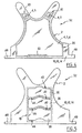
- Figure 3 shows the general shape of the panels 10, 12 and 14, and plates 24, 26, 28 received in the closed pocket 18 shown in dotted lines. These plates are suitable to cover most of the thorax.
- the rigid plate 26 is in one piece and extends over most of the element's surface thoracic.
- Figure 2 similarly shows the general shape protective elements 4, 5 and 6 received in the pocket 20 visible in dotted lines. This form is different from that of plates 24, 26, 28 and covers the thorax.
- the closure of the pocket 20 extends to the vicinity of a lower edge of the protection member 2.
- the thoracic protection member 2 further comprises a second pocket 20 parallel to the main pocket 20 above, partly superimposed on the main pocket and partly extending lower than the lower edge of the protection member 2, protruding from this edge.
- This pocket has a trapezoidal shape. It involves an opening with for example a zipper 22 at its upper edge. It is intended to receive a or two protective elements of the type of elements of protection 4, 5 and 6 mentioned above having a shape adapted to be received in this pocket.
- the vest includes then a set 1b of the type of that of FIG. 1, intended for the protection of the lower abdomen and having for this end a general triangular or trapezoidal shape.
- This assembly 1b is adapted to be removably attached by its upper edge to the lower edge of the assembly 1a of chest protection of Figures 2 and 3.
- the vest has for example a zipper 40 partly carried by a lower edge of the thoracic assembly 1a, and partly by an edge upper part of set 1b for the lower abdomen. when is in position, the lower abdomen protection set 1b covers the part of the secondary pocket of the thoracic assembly 1a which protrudes from the lower edge of this set.
- the vest also includes a 1c backpack for back protection, shown in Figures 4 and 5.
- the rigid plate 26 is here replaced by three curved plates and / or articulated 26 arranged in the same plane, one above the other from others and kept in this position by means allowing them to move moderately, by example to constitute a joint in flexion giving flexibility to the backpack.
- the three plates 26 are identical to each other. They have a generally rectangular shape presenting two large edges 42, 44 intended to extend horizontally when the vest is worn.
- the edge upper 42 has a protruding shape and the lower edge 44 has a re-entrant shape adapted to receive the edge projecting 42 from the adjacent plate 26. This association of the edges immobilizes the three plates in relative translation parallel to their large edges 42 and 44.
- the back pack includes two other pockets 20 intended to lie respectively on the shoulders of the user. These pockets 20 each include a ballistic element 4 and an anti-trauma element 5 received at stays in the pocket. Backpack includes two other pockets intended to extend above the shoulders of the user and to receive one or more removable or permanent protective elements.
- the vest has relative fastening means removable from thoracic assembly 1a to dorsal assembly 1c for example in the form of hook-and-loop tapes 48, in order to allow the relative position to be adjusted sets for wearing the vest.
- This possibility adjustment is advantageous considering that each of the sets 1a, 1b, 1c can be worn with a number of protection elements 4, 5 and 6 varying between 0 and 3, and that the thickness of each set is by therefore variable.
- each pocket 18, 20, 33, 35 extends over a major part of the surface of the whole associated protection.
- the vest may include a set adapted to otherwise or additionally protect the arms or neck.
- the vest may include removable sleeves not shown can be attached to sets thoracic and dorsal 1a, 1c by means of attachments by pressure.
- the vest may include only one of the aforementioned sets, for example thoracic 1a or dorsal 1c the other parts of the vest being of a type classic.
- the protection body may permanently receive at least one protective piece such as a plastic plate (for example in polypropylene reinforced by glass fibers), ceramic, hevlar®, resin, wire mesh (foam, foam and fabrics, rubber or whatever other material adapted to the aesthetics and nature of the protection provided. These materials may also be used for the protective element (s) removable. At least one of the protective parts to remains and / or at least one of the protective elements removable may have a joint and / or a bending.
- a plastic plate for example in polypropylene reinforced by glass fibers
- ceramic for example in polypropylene reinforced by glass fibers
- hevlar® hevlar®
- resin wire mesh
- Foam, foam and fabrics rubber or whatever other material adapted to the aesthetics and nature of the protection provided.
- the protection body may also include a permanent protective part and / or a removable protection adapted to ward off stab wounds.
- This piece may include at least one fabric and / or interlaced metal strips.
- the ballistic element 4 comprises twenty-four layers of an aramid fabric of type 4817 having the following characteristics: it is composed of 100% kevlar® 29 HT.
- the structure of this fabric is: 1100 Dtex chain; Weft: 1100 Dtex.
- This fabric has a canvas frame. Its texture is 8.8 x 8.3 (+/- 1). Its weight per m 2 is 192 gr / m 2 (+/- 5%). The total weight of this item is 1 kg.
- the anti-trauma element 5 comprises four layers of aramid fabric of type W 7660 covered with elastomer on the two faces of each layer.
- This fabric is made of 100% kevlar® 29 HT, having the structure: 3300 Dtex warp and 3300 Dtex weft.
- the frame is canvas, the texture is 4.5 x 4.5 (+/- 1) and the weight is 192 gr / m 2 (+/- 5%).
- the total weight of this item is 420 g.
- the anti-impact element 6 comprises two thicknesses cellular rubber foam and soft PVC between which are inserted cell type alveoli wrapped in a padded pocket.
- the weight of this element is 260 g.
- the ballistic element 4 is adapted to stop the ammunition with high penetrating power and to increase locally protection at the vital parts the wearer of the vest.
- the anti-trauma element 5 ensures the diffusion of the shock due to the impact of the ammunition in avoiding locally traumatizing the wearer's body.
- the combination according to the invention can make part of a protective suit or vest with protective coveralls attached to remains in the set or in the vest.
Landscapes
- Engineering & Computer Science (AREA)
- General Engineering & Computer Science (AREA)
- Health & Medical Sciences (AREA)
- General Health & Medical Sciences (AREA)
- Physical Education & Sports Medicine (AREA)
- Textile Engineering (AREA)
- Professional, Industrial, Or Sporting Protective Garments (AREA)
- Materials For Medical Uses (AREA)
- Thermotherapy And Cooling Therapy Devices (AREA)
- Joints Allowing Movement (AREA)
- Outer Garments And Coats (AREA)
- Laminated Bodies (AREA)
- Pivots And Pivotal Connections (AREA)
- Aiming, Guidance, Guns With A Light Source, Armor, Camouflage, And Targets (AREA)
Claims (22)
- Baugruppe zum Schutz des menschlichen Körpers, mit:dadurch gekennzeichnet, daß die Baugruppe derart ausgebildet ist, daß die steife Platte (26) ständig im Organ aufgenommen ist.einem schußsicheren Schutzelement (6) mit insgesamt flacher Form; undeinem Schutzorgan (2) mit insgesamt flacher Form, das vom Schutzelement (6) abnehmbare Tragemittel derart aufweist, daß das Organ und das Element im wesentlichen parallel sind, einander gegenüberliegen und miteinander in Berührung stehen, wobei das Organ eine steife Platte (26) aufweist,
- Baugruppe nach Anspruch 1, dadurch gekennzeichnet, daß die steife Platte (26) mindestens eine gelenkige Verbindung aufweist, die zwei Teile der Platte verbindet.
- Baugruppe nach irgendeinem der Ansprüche 1 bis 2, dadurch gekennzeichnet, daß sie mindestens eine Schaumstoffplatte (24, 28), die ständig am Schutzorgan (2) befestigt ist, sowie Mittel (18) aufweist, um die steife Platte und die Schaumstoffplatte parallel zueinander und einander gegenüberliegend zu halten, wobei die beiden Platten frei sind, sich zueinander zu bewegen, und die Schaumstoffplatte (28) derart angeordnet ist, daß sie sich zwischen der steifen Platte (26) und dem Körper erstreckt.
- Baugruppe nach Anspruch 3, dadurch gekennzeichnet, daß die Schaumstoffplatte auf eine Außenwand (10) des Schutzorgans (2) aufgeklebt ist.
- Baugruppe nach Anspruch 3 oder 4, dadurch gekennzeichnet, daß sie zwei Schaumstoffplatten (24, 28) aufweist, zwischen denen sich die steife Platte (26) erstreckt.
- Baugruppe nach irgendeinem der Ansprüche 1 bis 5, dadurch gekennzeichnet, daß sie mindestens zwei Schutzelemente (4, 5, 6) aufweist, die dazu eingerichtet sind, gleichzeitig abnehmbar vom Schutzorgan (2) getragen zu werden.
- Baugruppe nach irgendeinem der Ansprüche 1 bis 6, dadurch gekennzeichnet, daß das Schutzelement oder die Schutzelemente (4) dazu eingerichtet ist bzw. sind, Geschossen einer Feuerwaffe standzuhalten.
- Baugruppe nach irgendeinem der Ansprüche 1 bis 7, dadurch gekennzeichnet, daß die Tragemittel mindestens eine Tasche (20) aufweisen, die dazu eingerichtet ist, das Schutzelement (4, 5, 6) mindestens teilweise aufzunehmen.
- Baugruppe nach Anspruch 8, dadurch gekennzeichnet, daß sie mindestens zwei Taschen (20) aufweist, die mindestens zum Teil nicht übereinanderliegen.
- Baugruppe nach irgendeinem der Ansprüche 1 bis 9, dadurch gekennzeichnet, daß sie dazu bestimmt ist, mindestens eines der folgenden Körperteile zu schützen: den Brustkorb, den Bauch, den Unterleib, den Rücken, die Schulter.
- Schutzweste mit mindestens einer Baugruppe (1a, 1b, 1c) nach irgendeinem der Ansprüche 1 bis 10.
- Kombination enthaltend ein erstes Schutzelement (4) mit insgesamt flacher Form, das dazu eingerichtet ist, vor Geschossen von Schußwaffen zu schützen, und ein zweites Schutzelement (6) mit insgesamt flacher Form, das imstande ist, vor Stichen zu schützen, wobei die beiden Elemente (4, 6) übereinanderliegen, um derart auf dem Körper eines Benutzers getragen zu werden, daß das zweite Element (6) dem Körper näherliegt als das erste Element (4),
dadurch gekennzeichnet, daß das zweite Element (6) zwei Dicken bzw. Schichten (36) aus weichem Schaumstoff aufweist, sowie eine zwischen diese eingeschobene Dicke bzw. Schicht (38) aus Zellen bildendem, weichem Schaumstoff. - Kombination nach Anspruch 12, dadurch gekennzeichnet, daß sie außerdem ein drittes Schutzelement (5) mit insgesamt flacher Form aufweist, das zwischen das erste und zweite Element (4, 6) eingeschoben ist und dazu eingerichtet ist, gegenüber einem Aufprall zu schützen, der von einer Feuerwaffe herrührt.
- Kombination nach Anspruch 13, dadurch gekennzeichnet, daß das erste Element (4) eine Anzahl von Lagen aus Aramidtuch aufweist, die zwischen achtzehn und dreißig liegt, wobei das Tuch Kette und Schuß mit jeweils zwischen 800 und 1400 Dtex sowie ein Gewicht aufweist, das zwischen 172 und 222 g/m2 liegt, und daß das dritte Element (5) eine Anzahl von Lagen aus Aramidtuch aufweist, die zwischen eins und acht liegt, wobei die Lagen mindestens auf einer Fläche mit Elastomer abgedeckt sind und dieses Gewebe Kette und Schuß mit jeweils zwischen 2800 und 3800 Dtex sowie ein Gewicht aufweist, das zwischen 172 und 222 g/m2 liegt.
- Kombination nach irgendeinem der Ansprüche 12 bis 14, dadurch gekennzeichnet, daß mindestens das eine der Schutzelemente eine gelenkige Verbindung aufweist.
- Baugruppe zum Schutz des menschlichen Körpers, dadurch gekennzeichnet, daß sie eine Kombination nach irgendeinem der Ansprüche 12 bis 15 aufweist.
- Baugruppe nach Anspruch 16, dadurch gekennzeichnet, daß sie ein Schutzorgan (2) aufweist, das dazu eingerichtet ist, abnehmbar die Schutzelemente (4, 5, 6) der Kombination mit den übereinanderliegenden Elementen zu tragen.
- Baugruppe nach Anspruch 17, dadurch gekennzeichnet, daß die Baugruppe mindestens eine steife Platte (26) und mindestens eine Schaumstoffplatte (24, 28), die ständig am Schutzorgan (2) befestigt sind, und Mittel (18) zum Halten der beiden Platten parallel zueinander und einander gegenüberliegend aufweist, wobei die beiden Platten frei sind, sich zueinander zu bewegen, und wobei die Schaumstoffplatte (28) derart angeordnet ist, daß sie sich zwischen der steifen Platte (26) und dem Körper erstreckt.
- Baugruppe nach Anspruch 18, dadurch gekennzeichnet, daß die Baugruppe zwei Schaumstoffplatten (24, 28) aufweist, zwischen denen sich die steife Platte (26) erstreckt.
- Baugruppe nach Anspruch 18 oder 19, dadurch gekennzeichnet, daß die steife Platte (26) nur eine einzige ist und sich über den Hauptteil des Schutzorgans (2) erstreckt.
- Anordnung nach irgendeinem der Ansprüche 16 bis 20, dadurch gekennzeichnet, daß sie dazu bestimmt ist, mindestens einen der folgenden Körperteile zu schützen: den Brustkorb, den Bauch, den Unterleib, den Rücken, die Schulter.
- Schutzweste mit mindestens einer Baugruppe (la, 1b, 1c) nach irgendeinem der Ansprüche 16 bis 21.
Applications Claiming Priority (5)
| Application Number | Priority Date | Filing Date | Title |
|---|---|---|---|
| FR9707489A FR2764480B1 (fr) | 1997-06-17 | 1997-06-17 | Gilet de protection contre les balles et/ou les coups |
| FR9707489 | 1997-06-17 | ||
| FR9800304A FR2764481B1 (fr) | 1997-06-17 | 1998-01-14 | Gilet de protection contre les balles et/ou les coups |
| FR9800304 | 1998-01-14 | ||
| PCT/FR1998/001249 WO1998057559A1 (fr) | 1997-06-17 | 1998-06-15 | Gilet de protection contre les balles et/ou les coups |
Publications (2)
| Publication Number | Publication Date |
|---|---|
| EP0987963A1 EP0987963A1 (de) | 2000-03-29 |
| EP0987963B1 true EP0987963B1 (de) | 2002-09-18 |
Family
ID=26233614
Family Applications (1)
| Application Number | Title | Priority Date | Filing Date |
|---|---|---|---|
| EP98932204A Expired - Lifetime EP0987963B1 (de) | 1997-06-17 | 1998-06-15 | Kugel- und stichschutzjacke |
Country Status (7)
| Country | Link |
|---|---|
| EP (1) | EP0987963B1 (de) |
| AT (1) | ATE224154T1 (de) |
| AU (1) | AU8218898A (de) |
| DE (1) | DE69808081T2 (de) |
| ES (1) | ES2183390T3 (de) |
| FR (1) | FR2764481B1 (de) |
| WO (1) | WO1998057559A1 (de) |
Families Citing this family (8)
| Publication number | Priority date | Publication date | Assignee | Title |
|---|---|---|---|---|
| DE202007014036U1 (de) * | 2007-10-08 | 2009-02-19 | Müller, Lothar | Modulare Körperschutzweste, Schulterbereich-Schutzelement dafür sowie Befestigungselement für ein Schulterbereich-Schutzelement |
| RU2426062C1 (ru) * | 2010-04-02 | 2011-08-10 | Олег Савельевич Кочетов | Защитная куртка |
| RU2426059C1 (ru) * | 2010-04-02 | 2011-08-10 | Олег Савельевич Кочетов | Жилет защитный типа кс |
| RU2426061C1 (ru) * | 2010-04-02 | 2011-08-10 | Олег Савельевич Кочетов | Жилет защитный |
| RU2506526C2 (ru) * | 2012-02-10 | 2014-02-10 | Олег Савельевич Кочетов | Жилет защитный типа кс |
| RU2526678C2 (ru) * | 2012-05-17 | 2014-08-27 | Российская Федерация, от имени которой выступает Министерство Российской Федерации по делам гражданской обороны, чрезвычайным ситуациям и ликвидации последствий стихийных бедствий | Костюм боевой одежды спасателя |
| FR3043768B1 (fr) * | 2015-11-16 | 2018-06-01 | Paul Boye Technologies | Element de protection balistique pour gilet pare-balles |
| FR3056887B1 (fr) * | 2016-09-30 | 2019-05-10 | Gk Professional | Gilet de protection pare-coups |
Family Cites Families (6)
| Publication number | Priority date | Publication date | Assignee | Title |
|---|---|---|---|---|
| US3557384A (en) * | 1969-02-24 | 1971-01-26 | Us Army | Variable infantry armor system |
| US4535478A (en) * | 1983-05-20 | 1985-08-20 | Zuefle Tim T | Body armor |
| US4783853A (en) * | 1987-04-17 | 1988-11-15 | Zuber Christopher T | Protective body suit |
| GB2214405A (en) * | 1988-01-27 | 1989-09-06 | Michael Sacks | Protective garments |
| DE4214543A1 (de) * | 1992-04-29 | 1993-11-04 | Sst Sicherheits Und Systemtech | Dynamischer, teilflexibler koerperschutz gegen schlag-, schuss- und stichwaffenangriffe |
| US5584737A (en) * | 1994-08-01 | 1996-12-17 | Luhtala; Antti J. | Versatile safety device |
-
1998
- 1998-01-14 FR FR9800304A patent/FR2764481B1/fr not_active Expired - Fee Related
- 1998-06-15 EP EP98932204A patent/EP0987963B1/de not_active Expired - Lifetime
- 1998-06-15 DE DE69808081T patent/DE69808081T2/de not_active Expired - Lifetime
- 1998-06-15 AU AU82188/98A patent/AU8218898A/en not_active Abandoned
- 1998-06-15 AT AT98932204T patent/ATE224154T1/de not_active IP Right Cessation
- 1998-06-15 WO PCT/FR1998/001249 patent/WO1998057559A1/fr not_active Ceased
- 1998-06-15 ES ES98932204T patent/ES2183390T3/es not_active Expired - Lifetime
Also Published As
| Publication number | Publication date |
|---|---|
| EP0987963A1 (de) | 2000-03-29 |
| DE69808081T2 (de) | 2003-05-28 |
| FR2764481B1 (fr) | 1999-10-22 |
| ATE224154T1 (de) | 2002-10-15 |
| AU8218898A (en) | 1999-01-04 |
| ES2183390T3 (es) | 2003-03-16 |
| WO1998057559A1 (fr) | 1998-12-23 |
| FR2764481A1 (fr) | 1998-12-18 |
| DE69808081D1 (de) | 2002-10-24 |
Similar Documents
| Publication | Publication Date | Title |
|---|---|---|
| US4413357A (en) | Protective shields | |
| CA2591163C (fr) | Vetement modulaire | |
| EP2916672B1 (de) | Schutzkörperpanzerung mit vorderöffnung | |
| EP3564616B1 (de) | Weibliche schutzweste | |
| EP0987963A1 (de) | Kugel- und stichschutzjacke | |
| US5691028A (en) | Removable sleeve for padding a hazardous-duty garment strap | |
| FR2730301A1 (fr) | Gilet pare-balles a flottabilite positive permanente | |
| WO2012113875A1 (fr) | Vêtement de protection du tronc d'un individu à confort amélioré | |
| CA2827717C (fr) | Vetement de protection balistique | |
| WO2000028273A1 (fr) | Vetements pare-balles | |
| FR2725018A1 (fr) | Equipement permettant d'assurer la protection des personnes contre les eclats produits par des engins ou materiaux explosifs | |
| FR2764480A1 (fr) | Gilet de protection contre les balles et/ou les coups | |
| FR2634875A1 (fr) | Un bouclier portable pour personnes | |
| EP0425394A1 (de) | Kugelsichere Weste | |
| WO2005119162A2 (en) | Ballistic carrier garment | |
| FR2997609A1 (fr) | Gilet de protection pare-coups comprenant un panneau de protection interchangeable | |
| FR2738996A1 (fr) | Element de protection contre les coups, et gilet incorporant de tels elements de protection | |
| EP1486752A1 (de) | Panzerelement | |
| EP2840347A1 (de) | Schusssichere Schutzausrüstung, die seitliche Verschlussmittel umfasst | |
| EP2875742B1 (de) | Schusssichere Schutzausrüstung, die seitliche Verschlussmittel umfasst | |
| FR2997608A1 (fr) | Gilet de protection pare-coups presentant une ouverture frontale | |
| EP2786665B1 (de) | Schutzelement, das zwei Teile umfasst, die über eine Gelenkverbindung miteinander verbunden sind | |
| FR3056887A1 (fr) | Gilet de protection pare-coups | |
| EP3581046A1 (de) | Schutzausrüstung in form einer modulierbaren schutzweste | |
| FR2813387A1 (fr) | Dispositif de protection pare-balles des membres |
Legal Events
| Date | Code | Title | Description |
|---|---|---|---|
| PUAI | Public reference made under article 153(3) epc to a published international application that has entered the european phase |
Free format text: ORIGINAL CODE: 0009012 |
|
| 17P | Request for examination filed |
Effective date: 19991230 |
|
| AK | Designated contracting states |
Kind code of ref document: A1 Designated state(s): AT BE CH CY DE DK ES FI FR GB GR IE IT LI LU MC NL PT SE |
|
| 17Q | First examination report despatched |
Effective date: 20001018 |
|
| GRAG | Despatch of communication of intention to grant |
Free format text: ORIGINAL CODE: EPIDOS AGRA |
|
| GRAG | Despatch of communication of intention to grant |
Free format text: ORIGINAL CODE: EPIDOS AGRA |
|
| GRAH | Despatch of communication of intention to grant a patent |
Free format text: ORIGINAL CODE: EPIDOS IGRA |
|
| GRAH | Despatch of communication of intention to grant a patent |
Free format text: ORIGINAL CODE: EPIDOS IGRA |
|
| GRAA | (expected) grant |
Free format text: ORIGINAL CODE: 0009210 |
|
| AK | Designated contracting states |
Kind code of ref document: B1 Designated state(s): AT BE CH CY DE DK ES FI FR GB GR IE IT LI LU MC NL PT SE |
|
| PG25 | Lapsed in a contracting state [announced via postgrant information from national office to epo] |
Ref country code: NL Free format text: LAPSE BECAUSE OF FAILURE TO SUBMIT A TRANSLATION OF THE DESCRIPTION OR TO PAY THE FEE WITHIN THE PRESCRIBED TIME-LIMIT Effective date: 20020918 Ref country code: IE Free format text: LAPSE BECAUSE OF FAILURE TO SUBMIT A TRANSLATION OF THE DESCRIPTION OR TO PAY THE FEE WITHIN THE PRESCRIBED TIME-LIMIT Effective date: 20020918 Ref country code: FI Free format text: LAPSE BECAUSE OF FAILURE TO SUBMIT A TRANSLATION OF THE DESCRIPTION OR TO PAY THE FEE WITHIN THE PRESCRIBED TIME-LIMIT Effective date: 20020918 Ref country code: AT Free format text: LAPSE BECAUSE OF FAILURE TO SUBMIT A TRANSLATION OF THE DESCRIPTION OR TO PAY THE FEE WITHIN THE PRESCRIBED TIME-LIMIT Effective date: 20020918 |
|
| REF | Corresponds to: |
Ref document number: 224154 Country of ref document: AT Date of ref document: 20021015 Kind code of ref document: T |
|
| REG | Reference to a national code |
Ref country code: GB Ref legal event code: FG4D Free format text: NOT ENGLISH |
|
| REG | Reference to a national code |
Ref country code: CH Ref legal event code: EP |
|
| REG | Reference to a national code |
Ref country code: IE Ref legal event code: FG4D Free format text: FRENCH |
|
| REF | Corresponds to: |
Ref document number: 69808081 Country of ref document: DE Date of ref document: 20021024 |
|
| PG25 | Lapsed in a contracting state [announced via postgrant information from national office to epo] |
Ref country code: SE Free format text: LAPSE BECAUSE OF FAILURE TO SUBMIT A TRANSLATION OF THE DESCRIPTION OR TO PAY THE FEE WITHIN THE PRESCRIBED TIME-LIMIT Effective date: 20021218 Ref country code: DK Free format text: LAPSE BECAUSE OF FAILURE TO SUBMIT A TRANSLATION OF THE DESCRIPTION OR TO PAY THE FEE WITHIN THE PRESCRIBED TIME-LIMIT Effective date: 20021218 |
|
| PG25 | Lapsed in a contracting state [announced via postgrant information from national office to epo] |
Ref country code: PT Free format text: LAPSE BECAUSE OF FAILURE TO SUBMIT A TRANSLATION OF THE DESCRIPTION OR TO PAY THE FEE WITHIN THE PRESCRIBED TIME-LIMIT Effective date: 20021219 |
|
| GBT | Gb: translation of ep patent filed (gb section 77(6)(a)/1977) |
Effective date: 20021230 |
|
| REG | Reference to a national code |
Ref country code: GR Ref legal event code: EP Ref document number: 20020404244 Country of ref document: GR |
|
| NLV1 | Nl: lapsed or annulled due to failure to fulfill the requirements of art. 29p and 29m of the patents act | ||
| REG | Reference to a national code |
Ref country code: ES Ref legal event code: FG2A Ref document number: 2183390 Country of ref document: ES Kind code of ref document: T3 |
|
| REG | Reference to a national code |
Ref country code: IE Ref legal event code: FD4D Ref document number: 0987963E Country of ref document: IE |
|
| PG25 | Lapsed in a contracting state [announced via postgrant information from national office to epo] |
Ref country code: LU Free format text: LAPSE BECAUSE OF NON-PAYMENT OF DUE FEES Effective date: 20030615 Ref country code: CY Free format text: LAPSE BECAUSE OF FAILURE TO SUBMIT A TRANSLATION OF THE DESCRIPTION OR TO PAY THE FEE WITHIN THE PRESCRIBED TIME-LIMIT Effective date: 20030615 |
|
| PG25 | Lapsed in a contracting state [announced via postgrant information from national office to epo] |
Ref country code: MC Free format text: LAPSE BECAUSE OF NON-PAYMENT OF DUE FEES Effective date: 20030630 Ref country code: LI Free format text: LAPSE BECAUSE OF NON-PAYMENT OF DUE FEES Effective date: 20030630 Ref country code: CH Free format text: LAPSE BECAUSE OF NON-PAYMENT OF DUE FEES Effective date: 20030630 |
|
| PLBE | No opposition filed within time limit |
Free format text: ORIGINAL CODE: 0009261 |
|
| STAA | Information on the status of an ep patent application or granted ep patent |
Free format text: STATUS: NO OPPOSITION FILED WITHIN TIME LIMIT |
|
| 26N | No opposition filed |
Effective date: 20030619 |
|
| REG | Reference to a national code |
Ref country code: CH Ref legal event code: PL |
|
| REG | Reference to a national code |
Ref country code: FR Ref legal event code: CL |
|
| REG | Reference to a national code |
Ref country code: ES Ref legal event code: GD2A Effective date: 20070205 |
|
| REG | Reference to a national code |
Ref country code: FR Ref legal event code: PLFP Year of fee payment: 19 |
|
| PGFP | Annual fee paid to national office [announced via postgrant information from national office to epo] |
Ref country code: GR Payment date: 20160629 Year of fee payment: 19 |
|
| PGFP | Annual fee paid to national office [announced via postgrant information from national office to epo] |
Ref country code: FR Payment date: 20160627 Year of fee payment: 19 |
|
| PGFP | Annual fee paid to national office [announced via postgrant information from national office to epo] |
Ref country code: DE Payment date: 20160719 Year of fee payment: 19 Ref country code: IT Payment date: 20160629 Year of fee payment: 19 Ref country code: GB Payment date: 20160719 Year of fee payment: 19 |
|
| PGFP | Annual fee paid to national office [announced via postgrant information from national office to epo] |
Ref country code: ES Payment date: 20160729 Year of fee payment: 19 Ref country code: BE Payment date: 20160628 Year of fee payment: 19 |
|
| REG | Reference to a national code |
Ref country code: DE Ref legal event code: R119 Ref document number: 69808081 Country of ref document: DE |
|
| GBPC | Gb: european patent ceased through non-payment of renewal fee |
Effective date: 20170615 |
|
| REG | Reference to a national code |
Ref country code: FR Ref legal event code: ST Effective date: 20180228 |
|
| PG25 | Lapsed in a contracting state [announced via postgrant information from national office to epo] |
Ref country code: GB Free format text: LAPSE BECAUSE OF NON-PAYMENT OF DUE FEES Effective date: 20170615 Ref country code: DE Free format text: LAPSE BECAUSE OF NON-PAYMENT OF DUE FEES Effective date: 20180103 |
|
| PG25 | Lapsed in a contracting state [announced via postgrant information from national office to epo] |
Ref country code: FR Free format text: LAPSE BECAUSE OF NON-PAYMENT OF DUE FEES Effective date: 20170630 Ref country code: IT Free format text: LAPSE BECAUSE OF NON-PAYMENT OF DUE FEES Effective date: 20170615 Ref country code: GR Free format text: LAPSE BECAUSE OF NON-PAYMENT OF DUE FEES Effective date: 20180111 |
|
| REG | Reference to a national code |
Ref country code: BE Ref legal event code: MM Effective date: 20170630 |
|
| PG25 | Lapsed in a contracting state [announced via postgrant information from national office to epo] |
Ref country code: BE Free format text: LAPSE BECAUSE OF NON-PAYMENT OF DUE FEES Effective date: 20170630 |
|
| REG | Reference to a national code |
Ref country code: ES Ref legal event code: FD2A Effective date: 20181106 |
|
| PG25 | Lapsed in a contracting state [announced via postgrant information from national office to epo] |
Ref country code: ES Free format text: LAPSE BECAUSE OF NON-PAYMENT OF DUE FEES Effective date: 20170616 |