EP0988183B1 - Vorrichtung zur entfaltung eines luftsacks durch ein festes verkleidungsteil - Google Patents
Vorrichtung zur entfaltung eines luftsacks durch ein festes verkleidungsteil Download PDFInfo
- Publication number
- EP0988183B1 EP0988183B1 EP98924940A EP98924940A EP0988183B1 EP 0988183 B1 EP0988183 B1 EP 0988183B1 EP 98924940 A EP98924940 A EP 98924940A EP 98924940 A EP98924940 A EP 98924940A EP 0988183 B1 EP0988183 B1 EP 0988183B1
- Authority
- EP
- European Patent Office
- Prior art keywords
- door
- reaction plate
- air bag
- tether
- restraint apparatus
- Prior art date
- Legal status (The legal status is an assumption and is not a legal conclusion. Google has not performed a legal analysis and makes no representation as to the accuracy of the status listed.)
- Expired - Lifetime
Links
- 238000006243 chemical reaction Methods 0.000 claims abstract description 156
- 230000000153 supplemental effect Effects 0.000 claims description 52
- 238000005452 bending Methods 0.000 claims description 13
- 239000000463 material Substances 0.000 claims description 8
- 239000006260 foam Substances 0.000 claims description 3
- 238000001746 injection moulding Methods 0.000 claims description 3
- 239000012141 concentrate Substances 0.000 abstract description 6
- 239000002184 metal Substances 0.000 abstract description 4
- 239000004677 Nylon Substances 0.000 description 4
- 229920001778 nylon Polymers 0.000 description 4
- 238000010276 construction Methods 0.000 description 3
- 239000004744 fabric Substances 0.000 description 3
- 230000035939 shock Effects 0.000 description 3
- 239000004743 Polypropylene Substances 0.000 description 2
- 229910000831 Steel Inorganic materials 0.000 description 2
- 229920000122 acrylonitrile butadiene styrene Polymers 0.000 description 2
- 239000004676 acrylonitrile butadiene styrene Substances 0.000 description 2
- XECAHXYUAAWDEL-UHFFFAOYSA-N acrylonitrile butadiene styrene Chemical compound C=CC=C.C=CC#N.C=CC1=CC=CC=C1 XECAHXYUAAWDEL-UHFFFAOYSA-N 0.000 description 2
- 239000000203 mixture Substances 0.000 description 2
- 239000004417 polycarbonate Substances 0.000 description 2
- -1 polypropylene Polymers 0.000 description 2
- 229920001155 polypropylene Polymers 0.000 description 2
- 239000010959 steel Substances 0.000 description 2
- 238000003466 welding Methods 0.000 description 2
- 229920007019 PC/ABS Polymers 0.000 description 1
- 239000004721 Polyphenylene oxide Substances 0.000 description 1
- 239000004793 Polystyrene Substances 0.000 description 1
- 239000010960 cold rolled steel Substances 0.000 description 1
- 239000002537 cosmetic Substances 0.000 description 1
- 238000009472 formulation Methods 0.000 description 1
- 238000013467 fragmentation Methods 0.000 description 1
- 238000006062 fragmentation reaction Methods 0.000 description 1
- 238000002347 injection Methods 0.000 description 1
- 239000007924 injection Substances 0.000 description 1
- 230000014759 maintenance of location Effects 0.000 description 1
- 238000000034 method Methods 0.000 description 1
- 239000004033 plastic Substances 0.000 description 1
- 229920003023 plastic Polymers 0.000 description 1
- 229920000515 polycarbonate Polymers 0.000 description 1
- 229920000728 polyester Polymers 0.000 description 1
- 229920000098 polyolefin Polymers 0.000 description 1
- 229920006124 polyolefin elastomer Polymers 0.000 description 1
- 229920006380 polyphenylene oxide Polymers 0.000 description 1
- 229920002223 polystyrene Polymers 0.000 description 1
- 229920002635 polyurethane Polymers 0.000 description 1
- 239000004814 polyurethane Substances 0.000 description 1
- 238000010079 rubber tapping Methods 0.000 description 1
- 238000000926 separation method Methods 0.000 description 1
- 230000007704 transition Effects 0.000 description 1
Images


Classifications
-
- B—PERFORMING OPERATIONS; TRANSPORTING
- B60—VEHICLES IN GENERAL
- B60R—VEHICLES, VEHICLE FITTINGS, OR VEHICLE PARTS, NOT OTHERWISE PROVIDED FOR
- B60R21/00—Arrangements or fittings on vehicles for protecting or preventing injuries to occupants or pedestrians in case of accidents or other traffic risks
- B60R21/02—Occupant safety arrangements or fittings, e.g. crash pads
- B60R21/16—Inflatable occupant restraints or confinements designed to inflate upon impact or impending impact, e.g. air bags
- B60R21/20—Arrangements for storing inflatable members in their non-use or deflated condition; Arrangement or mounting of air bag modules or components
- B60R21/215—Arrangements for storing inflatable members in their non-use or deflated condition; Arrangement or mounting of air bag modules or components characterised by the covers for the inflatable member
- B60R21/216—Arrangements for storing inflatable members in their non-use or deflated condition; Arrangement or mounting of air bag modules or components characterised by the covers for the inflatable member comprising tether means for limitation of cover motion during deployment
-
- B—PERFORMING OPERATIONS; TRANSPORTING
- B60—VEHICLES IN GENERAL
- B60R—VEHICLES, VEHICLE FITTINGS, OR VEHICLE PARTS, NOT OTHERWISE PROVIDED FOR
- B60R21/00—Arrangements or fittings on vehicles for protecting or preventing injuries to occupants or pedestrians in case of accidents or other traffic risks
- B60R21/02—Occupant safety arrangements or fittings, e.g. crash pads
- B60R21/16—Inflatable occupant restraints or confinements designed to inflate upon impact or impending impact, e.g. air bags
- B60R21/20—Arrangements for storing inflatable members in their non-use or deflated condition; Arrangement or mounting of air bag modules or components
- B60R21/215—Arrangements for storing inflatable members in their non-use or deflated condition; Arrangement or mounting of air bag modules or components characterised by the covers for the inflatable member
- B60R21/2165—Arrangements for storing inflatable members in their non-use or deflated condition; Arrangement or mounting of air bag modules or components characterised by the covers for the inflatable member characterised by a tear line for defining a deployment opening
-
- B—PERFORMING OPERATIONS; TRANSPORTING
- B29—WORKING OF PLASTICS; WORKING OF SUBSTANCES IN A PLASTIC STATE IN GENERAL
- B29L—INDEXING SCHEME ASSOCIATED WITH SUBCLASS B29C, RELATING TO PARTICULAR ARTICLES
- B29L2031/00—Other particular articles
- B29L2031/30—Vehicles, e.g. ships or aircraft, or body parts thereof
- B29L2031/3005—Body finishings
- B29L2031/3038—Air bag covers
-
- B—PERFORMING OPERATIONS; TRANSPORTING
- B60—VEHICLES IN GENERAL
- B60R—VEHICLES, VEHICLE FITTINGS, OR VEHICLE PARTS, NOT OTHERWISE PROVIDED FOR
- B60R21/00—Arrangements or fittings on vehicles for protecting or preventing injuries to occupants or pedestrians in case of accidents or other traffic risks
- B60R21/02—Occupant safety arrangements or fittings, e.g. crash pads
- B60R21/16—Inflatable occupant restraints or confinements designed to inflate upon impact or impending impact, e.g. air bags
- B60R21/20—Arrangements for storing inflatable members in their non-use or deflated condition; Arrangement or mounting of air bag modules or components
- B60R21/215—Arrangements for storing inflatable members in their non-use or deflated condition; Arrangement or mounting of air bag modules or components characterised by the covers for the inflatable member
- B60R21/216—Arrangements for storing inflatable members in their non-use or deflated condition; Arrangement or mounting of air bag modules or components characterised by the covers for the inflatable member comprising tether means for limitation of cover motion during deployment
- B60R2021/2163—Arrangements for storing inflatable members in their non-use or deflated condition; Arrangement or mounting of air bag modules or components characterised by the covers for the inflatable member comprising tether means for limitation of cover motion during deployment with energy absorbing or elastic means
-
- B—PERFORMING OPERATIONS; TRANSPORTING
- B60—VEHICLES IN GENERAL
- B60R—VEHICLES, VEHICLE FITTINGS, OR VEHICLE PARTS, NOT OTHERWISE PROVIDED FOR
- B60R21/00—Arrangements or fittings on vehicles for protecting or preventing injuries to occupants or pedestrians in case of accidents or other traffic risks
- B60R21/02—Occupant safety arrangements or fittings, e.g. crash pads
- B60R21/16—Inflatable occupant restraints or confinements designed to inflate upon impact or impending impact, e.g. air bags
- B60R21/20—Arrangements for storing inflatable members in their non-use or deflated condition; Arrangement or mounting of air bag modules or components
- B60R21/217—Inflation fluid source retainers, e.g. reaction canisters; Connection of bags, covers, diffusers or inflation fluid sources therewith or together
- B60R21/2171—Inflation fluid source retainers, e.g. reaction canisters; Connection of bags, covers, diffusers or inflation fluid sources therewith or together specially adapted for elongated cylindrical or bottle-like inflators with a symmetry axis perpendicular to the main direction of bag deployment, e.g. extruded reaction canisters
Definitions
- This invention relates generally to a passive supplemental inflatable restraint (PSIR) system having a PSIR door that is integrally formed with an instrument panel and, more particularly, to such a system having a PSIR door integrally formed with a hard first-surface instrument panel.
- PSIR passive supplemental inflatable restraint
- a passive supplemental inflatable restraint system having a PSIR door that is integrally formed into an automotive vehicle instrument panel must also include some provision for guiding or otherwise facilitating the opening and partial separation of that PSIR door from the instrument panel that it is integrally formed with. This is particularly true of PSIR doors that are integrally formed into hard first-surface instrument panels.
- the "first-surface" of a panel is the cosmetic exterior surface that would be visible to a vehicle occupant.
- Hard first-surface panels are typically formed by injection molding one or more plastic materials.
- United States Patent Number 5,738,366 discloses an air bag system that includes a chute structure and a deployment door.
- the deployment door is not formed integrally with the vehicle panel in which it is located.
- the deployment door has a pivotal door panel against which the air bag exerts a pressure force when the air bag is deployed. This causes the deployment door to pivot to an open position.
- United States Patent Number 5,072,967 which shows the features of the preamble of claim 1, discloses a cover assembly for an air bag restraint having a smooth cover and a load bearing insert for concealing an air bag restraint system.
- the insert is formed in an opening in an instrument panel and is engaged by the air bag during deployment.
- a passive supplemental restraint apparatus for an automotive vehicle, the apparatus comprising: an interior vehicle panel; an air bag deployment door integrally formed in the vehicle panel, the air bag deployment door having a perimeter, at least a portion of the perimeter defined by a frangible marginal edge; an air bag dispenser supported by a support structure adjacent a door inner surface opposite a door outer surface; and an air bag supported in an air bag receptacle of the air bag dispenser, the air bag having an inner end operatively connected to the air bag dispenser and an outer end disposed adjacent the air bag deployment door; characterized in that: the apparatus further comprises a reaction plate connected to the support structure and disposed between the air bag and the air bag deployment door to receive the force of air bag deployment from the dispenser and to direct and distribute that force against the door inner surface to separate the door from the vehicle panel along the frangible marginal edge of the door, wherein the reaction plate includes a pivotable panel portion configured to pivot outward under the force of air bag inflation and a tether that integrally extends from the
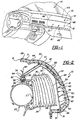
- a first embodiment of a passive supplemental restraint apparatus for an automotive vehicle is generally indicated at 10 in Figs. 1-3.
- a second embodiment is generally indicated at 10' in Figs. 4-7.
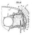
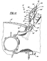
- a third embodiment is generally indicated at 10" in Figs. 9-11.
- Reference numerals with the designation prime (') in Figs. 4-7 and double prime (") in Figs. 9-11 indicate alternative configurations of elements that also appear in the first embodiment. Where a portion of the following description uses a reference numeral to refer to the figures, we intend that portion of the description to apply equally to elements designated by primed numerals in Figs. 4-7 and double-primed numerals in Figs. 9-11.
- the passive supplemental restraint apparatus is shown hidden behind an automotive vehicle passenger-side dash panel 12 below a windshield 14 of the vehicle.
- the apparatus includes the panel 12, and an air bag deployment door 16 integrally formed in the panel 12 and having a perimeter defined, in part, by a hidden marginal edge 18.
- the perimeter may, also be defined as the lateral boundary of the door 16 - the door 16 being defined as that portion of the integrally formed panel 12 and door 16 that is separable or bendable from the panel 12 under the force of air bag inflation.
- the door 16 and the vehicle dash panel 12 are integrally formed as a single unitary piece.
- an air bag dispenser assembly 20 is supported behind the door 16, i.e., on a side of the door 16 opposite a door outer surface 22.
- the dispenser 20 is also disposed adjacent and aligned with the air bag deployment door 16.
- the dispenser 20 may be any suitable type of air bag dispenser to include, for example, the dispenser described in US-A-5,564,731.
- An air bag 24 is supported in an air bag receptacle 26 of the air bag dispenser 20 and is operatively connected to the air bag dispenser 20 at an open end 27 of the air bag 24.
- a closed outer end 30 of the air bag 24 is disposed adjacent the air bag 24 deployment door 16.
- a rigid metal reaction plate 28 is disposed between the air bag 24 and the air bag deployment door 16.
- the reaction plate 28 receives the force of air bag deployment when the air bag 24 inflates and expands out of the dispenser 20.
- the reaction plate 28 directs and distributes that force across the door 16 to predictably separate the door 16 from the panel 12 along the hidden marginal edge 18 of the door 16.
- the reaction plate 28 also serves to prevent air bag 24 opening forces from concentrating in other locations on the door 16 that might result in door 16 or panel 12 fractures and/or fragmentation.
- the reaction plate 28 is positioned to concentrate air bag opening forces along a portion of the hidden marginal edge 18 that extends along the forward marginal edge 46 of the door 16.
- the reaction plate 28 is positioned in this way to initiate marginal edge tearing at the forward marginal edge 46 and then allow the tearing to propagate upward along the two side edges of the door 16. Alternatively, marginal edge tearing may be initiated at the forward marginal edge 46 and along the two side edges virtually simultaneously.
- the reaction plate 18 is preferably made of cold rolled steel but may be made from any other material having suitable bending and force-distributing characteristics.
- the reaction plate 28 includes a reaction plate outer marginal edge 32 having a shape generally identical to that of the hidden marginal edge 18 of the air bag deployment door 16.
- the reaction plate marginal edge 32 is aligned with the hidden marginal edge 18 of the air bag deployment door 16 to concentrate air bag 24 inflation stress along the hidden marginal edge 18 of the air bag deployment door 16.
- the reaction plate 28 is pivotally attached along a reaction plate inner edge 34 to the air bag dispenser apparatus 20.
- the reaction plate 28 may be pivotally attached to a portion of the panel 12 or other surrounding support structures.
- An outer portion of the reaction plate 28, generally indicated at 35 in Figs. 2 and 3, is outwardly and upwardly pivotable away from the air bag dispenser 20.
- the outer reaction plate portion 35 pivots by bending along a first horizontal hinge line 36 of the reaction plate 28 that extends parallel to and adjacent the. rigidly attached inner plate edge 34.
- the hinge line 36 defines a marginal inner edge of the outer portion 35 of the reaction plate.
- the outer portion 35 of the reaction plate also pivots by bending along a second horizontal hinge line 37 of the reaction plate 28 that extends parallel to the first hinge line 36.
- the outer portion 35 of the reaction plate 28 is disposed adjacent a door inner surface 38 and opposite the outer door surface 22.
- Three horizontal ribs, shown at 40 in Figs. 2 and 3, extend integrally inward from the door inner surface 38 to a point adjacent a lower panel 42 of the outer portion 35 of the reaction plate as shown in Figs. 2 and 3.
- the ribs 40 space the reaction plate lower panel 42 from the door inner surface 38.
- the ribs 40 allow the reaction plate 28 to be positioned in a plane that is generally perpendicular to the direction of air bag 24 deployment while remaining in close proximity to the door 16.
- the ribs 40 also allow the door 16 to be designed with outer contours that do not necessarily correspond to the reaction plate 28 configuration. In other embodiments the ribs 40 may be of any suitable configuration and orientation known in the art.
- the air bag deployment door 16 has a curved rectangular shape defined by relatively straight aft 44 and forward 46 marginal edges and a pair of arcuate side marginal edges 48.
- the forward 46 and side 48 edges comprise a frangible region of reduced cross section.
- the rear edge 44 may comprise a styling seam or groove intended to define the rear edge 44 of the door 16. In other embodiments the rear edge 44 may be hidden or there may be no "rear edge". In other words, the transition from the door to the panel 12 may be uninterrupted.
- styling seam may be functional or merely aesthetic. Where the styling seam is functional, it may be adapted to act as a bending hinge 44 when the door 16 is forced open and separated from the surrounding vehicle panel 12 along the frangible forward 46 and side 48 marginal edges.
- the bending hinge 44 allows the door 16 to swing outward and upward from the panel 12 during air bag 24 deployment while retaining the door 16 to the panel 12.
- the styling seam may also be designed as a frangible region of reduced cross section in similar fashion to the forward 46 and side 48 edges.
- a first pair of flexible tethers are generally indicated at 50 in Figs. 2 and 3.
- Each tether comprises PVC-coated nylon and has an outer end portion 52 fastened to the door inner surface 38 and an inner end portion 54 fastened to the air bag dispenser assembly 20.
- the first pair of flexible tethers 50 may be fastened to the panel 12 or other adjacent support structures instead of the dispenser 20.
- the tethers 50 may incorporate any one or more of a number of different tether constructions known in the art.
- One example of an acceptable tether construction is disclosed in US-A-5,564,731, is assigned to the assignee of the present invention.
- each tether 50 of the first pair of tethers is fastened to the air bag dispenser assembly 20 at a tether control point shown at 56 in Fig. 2 adjacent the reaction plate inner edge 34.
- the tether inner end portions 54 are fastened by folding them within a U-shaped channel 58 formed along the reaction plate inner edge 34.
- a row of holes 60 is formed along each side of the U-shaped reaction plate channel 58 to receive fasteners 62 that attach the reaction plate 28 to an elongated rectangular air bag dispenser flange 64.
- the dispenser flange 64 is horizontally disposed and extends integrally upward from the air bag dispenser apparatus 20.
- the flange 64 includes a row of flange holes 66 corresponding to the holes in the U-shaped reaction plate channel 58.
- One or more of the fasteners that connect the reaction plate 28 to the dispenser assembly 20 also pass through the portion of each tether inner end 54 that is folded within the U-shaped channel 58.
- each tether 50 of the first pair of tethers is fastened to the door 16 by eight heat-staked pins 68.
- the pins 68 extend integrally inward from the air bag 24 deployment door 16 as shown in Fig. 8.
- the pins 68 are preferably formed with the door 16 and the vehicle panel 12 as a single unitary piece.
- Other embodiments may use hot staked bosses as disclosed in US-A-5,564,731, assigned to the assignee of the present invention.
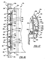
- Still other embodiments may use screws 76b engaged with screw bosses as is representatively shown at 67 in Fig. 17.
- the screw bosses 67 may be integrally formed to extend inward from the door 16.
- the bosses 67 may be threaded or unthreaded for use with self-tapping screws.
- Other embodiments may use any number of suitable fastening means known in the art.
- the air bag dispenser apparatus 10 described above is optimized to open integral doors in instrument panels, comprising hard outer or "first" surfaces, e.g., injection-molded panels.
- the invention may also be used where, as shown in Fig. 2, the hard outer surface is covered with a flexible skin 69 or skin 69 and foam 71 layers.
- a flexible skin 69 may be applied to cover at least a portion of the vehicle dash panel 12 and/or air bag deployment door 16 in a layered disposition.
- a foam layer 71 may also be included between the skin 69 and a portion of the panel 12 and/or the door 16.
- the door 16 and panel 12 preferably comprise an injection molded polycarbonate/acrylonitrile butadiene styrene blend (PC/ABS) or polypropylene.
- PC ABS polycarbonate/acrylonitrile butadiene styrene blend
- polypropylene examples include GE MC 8002 and Dow Pulse # 830.
- An example of an acceptable polypropylene is Montell #BR33GC.
- Other suitable materials may include polyesters, polyurethanes, polyphenylene oxide, polystyrenes, polyolefins, or polyolefin elastomers.
- the air bag deployment door 16' is defined by a visible marginal edge 18' and includes eight doghouse-shaped fastener brackets 70.
- Each fastener bracket 70 extends integrally inward toward the air bag dispenser assembly 20' from the door inner surface 38' in place of the ribs 40 of the first embodiment.
- Each fastener bracket 70 includes an attachment surface 72 spaced inwardly from and supported generally parallel to the door inner surface 38'.
- the fastener brackets 70 are preferably integrally formed with the door 16' and the vehicle dash panel 12' as a single unitary piece.
- the first tether 50' of the second embodiment makes up a portion of a single continuous tether sheet rather than comprising two separate tethers as in the first embodiment.
- an outer end 52' of the first tether 50' is attached to a forward portion 74 of the door 16' adjacent a forward marginal edge 46' of the door 16' disposed opposite the hinge 44'.
- four rivets 76 attach the outer end 52' of the first tether 50' to the attachment surfaces 72 of four fastener brackets 70 formed on the forward portion 74 of the door 16.
- the fastener brackets 70 support the rivets 76 without affecting the aesthetic continuity of the outer door surface 22'.
- other fastener bracket configurations including heat staking pins and screw bosses and other suitable types of fasteners and fastening methods may be used as is known in the art.
- each fastener bracket 70 includes a fastener aperture 78 disposed through the attachment surface 72 of the bracket 70 to receive one of the rivets 76.
- Each rivet 76 comprises a shaft portion that extends through the aperture 78 and also through a hole formed in the first tether 50' to hold the first tether 50' to the fastener bracket 70 in conventional fashion.
- the four fastener brackets 70 that attach the first tether 50' to the door 16' extend integrally inward from the door inner surface 38' adjacent a lower marginal region of the door 16' to a point adjacent the reaction plate 28'. Similar to the ribs 40 of the first embodiment, the fastener brackets 70 present the reaction plate lower panel 42' in a plane more perpendicular to the direction of air bag 24' deployment from the dispenser 20'. In other words, the fastener brackets 70 span the space between the outwardly curved lower marginal door region and the generally vertical reaction plate lower panel 42'.
- the single continuous tether sheet that includes the first flexible tether 50' also includes a second flexible tether, generally indicated at 80 in Figs. 4 and 7.
- the second tether 80 has an inner end portion 82 fastened to the air bag dispenser assembly 20' at the tether control point 56'. In other embodiments the second tether 80 may be secured either to the panel 12' or to another adjacent structure.
- the second flexible tether 80 has an outer end portion, shown at 84 in Figs. 4 and 7, that is fastened to an aft portion 86 of the door 16' disposed between the forward door portion 74 and the hinge 44'.
- the second tether 80 ties the aft door portion 86 to the control point 56' to prevent any portion of the door from over-rotating towards the windshield 14 and breaking off at one of several potential bending points including the hinge 44.
- the respective inner ends 54', 82 of the first 50' and second 80 tethers are riveted to an elongated rectangular flange 64' at the tether control point 56'.
- the flange 64' extends integrally upward from the air bag receptacle portion 26' of the air bag dispenser assembly 20'.
- the tether inner ends 54', 82 are sandwiched between the flange 64' and an elongated metal bar 90. Rivets 92 pass through the flange 64', the tethers 50', 80 and the bar 90.
- the air bag receptacle 26' includes a mouth 94 disposed adjacent the air bag deployment door 16'.
- the mouth 94 has a width measured across the mouth in a direction perpendicular to the hinge 44', i.e., in a generally vertical direction.
- the hinge 44' is spaced from the mouth 94 a distance equal to at least half of the mouth width. The hinge 44' is displaced in this manner to reduce the maximum opening angle at the hinge 44' to reduce material deformation and stress in the hinge during air bag 24 deployment.
- a pair of rigid stop members are operatively connected to the reaction plate 28' and the air bag dispenser 20'.
- the stop members 96 limit reaction plate 28' opening travel.
- the stop members 96 may arrest the reaction plate 28 in a position that will prevent the door 16' from returning to its original position after air bag 24 deployment.
- Each stop member is preferably fabricated from steel but may be made of other suitably rigid materials.
- the stop members 96 are slidably supported in slots representatively shown at 98 in Fig. 7 and disposed at opposite lateral sides of the receptacle portion 26' of the air bag dispenser apparatus 20'. Each stop member 96 is fixed to the reaction plate 28' at a stop point representatively shown at 100 in Fig. 7. The stop point 100 disposed between the first hinge line 36' and a reaction plate outer marginal edge 32' disposed opposite the reaction plate inner edge 34'.
- the outer panel portion 42'of the reaction plate 28' is outwardly and upwardly pivotable away from the air bag dispenser 20' by bending the reaction plate 28' along a second horizontal hinge line shown at 102 in Fig. 7.
- the second hinge line 102 is disposed horizontally across the reaction plate 28' adjacent the stop point 100 and extends generally parallel to the first hinge line 36'.
- the second hinge line 102 is spaced approximately one-third the distance between the first hinge line 36' and the reaction plate outer marginal edge 32'.
- This double hinge arrangement allows the reaction plate 28' to bend into an outwardly-rotated and upwardly extended position. In this position the plate 28' prevents the air bag deployment door 16' from rebounding off the tethers 50', 80 and returning to its original position immediately after a deploying air bag 24' has forced the door 16' open.
- Each stop member 96 is an elongated steel pin having a cylindrical shaft portion 104 as is representatively shown in Fig. 7.
- Inner 106 and outer 108 circular disk-shaped stop flanges are disposed at respective inner and outer distal ends of the shaft portion 104 of each stop member 96.
- the inner stop flange 106 of each stop member 96 extends radially and integrally outward from the shaft portion 104.
- the outer stop flange 108 of each stop member 96 is preferably fixed to the reaction plate 28' by spot welding or arc welding.
- the elongated slots 98 on either side of the air bag receptacle 26 each have a width slightly greater than that of the shaft portion 104 of each stop member 96.
- the shaft portion 104. of each stop member 96 is slidably disposed within one of the slots 98 to allow the stop members 96 to move between pre-inflation stowed positions, representatively shown in Fig. 4, and post-inflation deployed positions, representatively shown in Fig. 7.
- the reaction plate 28' pulls the stop members 96 from the stowed position to the deployed position when the reaction plate 28' opens under the force of an inflating air bag 24'.
- the inner stop flanges 106 engage the slot 98 and arrest reaction plate 28' movement.
- the stop members 96 arrest the reaction plate 28' in a position to prevent the door 16' from returning to its original position following air bag deployment.
- the frangible marginal edge 18" defines the entire perimeter of the air bag deployment door 16".
- the frangible marginal edge 18" extends completely around the air bag deployment door 16" in an unbroken circuit as is best shown in Fig. 9.
- a pair of flexible tethers, representatively indicated at 50" in Figs. 10 and 11, is fastened between the air bag deployment door 16" and the reaction plate 28".
- Each tether 50" includes an inner end portion 82" fastened to the door 16", an outer end portion 84" fastened to the door 16" and a middle portion 83 fastened to the reaction plate 28" between the second hinge line 102" and the reaction plate outer marginal edge 32".
- the middle portion 83 of each tether 50" is disposed approximately midway between the inner 82" and outer 84" end portions of each tether 50".
- the air bag deployment door 16" includes only four of the fastener brackets 70" disposed in a rectangular pattern as shown in Fig. 9.
- the inner end portion 82" and outer end portion 84" of each tether 50" are fastened to the attachment surface of one of the four fastener brackets 70" by rivets 76" as shown in Figs. 10 and 11.
- the middle portion 83 of each tether 50" is fastened to the reaction plate 28" between the second hinge line 102" and the reaction plate outer marginal edge 32" by a rivet 110.
- FIG. 9-11 nine vertical door ribs 112 extend integrally inward from the door inner surface 38" to a point adjacent the reaction plate 28".
- 24 short horizontal door ribs 114 connect adjacent vertical door ribs 112 to form a rectangular grid pattern best shown in Fig. 9.
- a plurality of vertical 116 and horizontal 118 panel ribs also extend integrally inward from an inner surface of the vehicle panel 12" adjacent the frangible marginal edge 18" of the door perimeter and are spaced apart around the door perimeter.
- the door ribs 112, 114 and panel ribs 116, 118 stiffen the door 16" and vehicle panel 12" against air bag opening shock and help concentrate opening forces along the frangible marginal edge 18" between the panel 12" and the door 16".
- the door ribs 112, 114 and panel ribs 116, 118 are integrally formed with the door 16" and the vehicle panel 12" as a single unitary piece by injection molding.
- the stop members 96" of the third embodiment limit how far the reaction plate 28" can bend, leaving the reaction plate 28" in an a generally vertical position.
- the upwardly-bent reaction plate 28" and the tethers 50" of the third embodiment hold the air bag deployment door 16" away from vehicle occupants.
- tearing may occur along the lower edge portion 120, side edge portions 122 and upper edge portion 124 virtually simultaneously.
- any one of a number of different configurations may be employed to arrest reaction plate 28 travel in a position to prevent an air bag door 16 from returning to its original position.
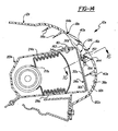
- FIG. 12-16 A fourth embodiment of a passive supplemental restraint apparatus is generally shown at 10s in Figs. 12-16.
- Reference numerals with the suffix "s" in Figs. 12-16 indicate alternative configurations of elements that also appear in the third embodiment. Where portions of the third embodiment description use reference numerals to refer to the figures, we intend those portions to apply equally to elements designated by the suffix "s" in Figs. 12-16.
- the passive supplemental restraint apparatus generally indicated at 10s includes first and second vertically-disposed elongated flexible nylon tethers, generally indicated at 50s, 51s in Fig. 16, and representatively indicated at 50s in Figs. 12 and 13.
- the tethers 50s, 51s slidably engage the door 16s rather than being fixed to the door 16s as disclosed in the description of the third embodiment.
- the apparatus 10s includes a flat, elongated flexible nylon fabric strap, generally indicated at 126 in Figs. 12-16.
- the strap 126 has a length extending between two strap ends and is horizontally disposed flat against the door 16s. As is best shown in Fig. 16, the strap 126 is fastened to the door 16s at first, second, third and fourth spaced attachment points 128, 130, 132, 134.
- Each flexible tether 50s, 51s includes a tether loop, representatively shown at 157 in Figs. 12 and 13 and at 157 and 159, respectively, in Fig. 16.
- the loop portion 157 of each tether 50s, 51s extends from at least one common tether loop attachment portion.
- the tether loop attachment portions each comprise first and second tether loop ends, representatively shown at 156, 158 in Figs. 12 and 13.
- Fasteners 161 extend through a strap retention member 163, both tether loop ends 156, 158, the reaction plate 28s and the air bag dispenser 20s.
- the fasteners 161 fasten the tether loop ends 156, 158 together, and fasten the loop ends 156 and reaction plate 28s to the air bag dispenser 20s adjacent the reaction. plate inner edge 34.
- the first tether loop end 156 of each tether 50s, 51s may be attached at a different location than the second tether loop end 158 of each tether 50s, 51s.
- a middle portion 136 of the first flexible tether 50s slidably extends between the door 16s and the strap 126, perpendicular to the length of the strap 126, and passes between the first and second attachment points 128, 130.
- a middle portion 138 of the second flexible tether 51s slidably extends between the door 16s and the strap 126, perpendicular to the length of the strap 126, and passes between the third and fourth attachment points 132, 134.
- the strap 126 holds the flexible tethers 50s, 51s against the door 16s while allowing the flexible tethers 50s, 51s to slide longitudinally through a pair of slots 140, 142.
- the slots 140, 142 are formed between the strap 126, the door 16s and the attachment points 128-134 as best shown in Figs. 12, 13 and 16.
- the apparatus (10s) includes first, second, third and fourth screw bosses, shown at 144, 146, 148 and 150 in Fig. 16 and representatively shown at 144 in Figs. 14 and 15.
- the bosses 144-150 extend integrally inward from a door inner surface 38s to the respective first, second, third and fourth attachment points 128-134.
- the screw bosses 144-150 are integrally formed with the door 16s as a unitary piece and are aligned horizontally along the door inner surface 38s.
- screw-type fasteners 152 extend through respective annular washers 154 and attach the strap 126 to the respective first, second, third and fourth bosses 144-150. by threadedly engaging the bosses 144-150.
- a generally rectangular reaction plate 28s is attached to an air bag dispenser assembly 20s along a reaction plate inner edge 34s, as shown in Figs. 12-15.
- An outer portion 35s of the reaction plate 28s is outwardly pivotable away from the air bag dispenser assembly 20s by bending the reaction plate 28s along a hinge line 36s extending parallel to the reaction plate inner edge 34s.
- the reaction plate 28s Prior to air bag inflation, the reaction plate 28s is bent at the hinge line 36s approximately 85° downward from horizontal. Following air bag inflation, the reaction plate 28s is bent approximately 85° upward from horizontal.
- Each flexible tether 50s, 51s has a length extending between first and second tether ends, representatively shown at 156 and 158, respectively, in Figs. 12 and 13.
- the first and second tether ends 156, 158 of each flexible tether 50s, 51s are fastened to the air bag dispenser assembly 20s adjacent the reaction plate inner edge 34s forming tether loops as shown in Figs. 12 and 13.
- a middle tether portion 160 of the first flexible tether 50s, 51s slidably engages the outer portion 35s of the reaction plate 28s.
- a middle tether portion of the second flexible tether 51s slidably engages the outer portion 35s of the reaction plate 28s at a point spaced laterally from the point where the first flexible tether 50s engages the outer portion 35s of the reaction plate 28s.
- respective outer portions 162, 164 of the flexible tethers 50s, 51s, disposed between the middle tether portions 160 and the first tether ends 156 slidably extend between the door 16s and the strap 126 as described above.
- the first flexible tether 50s slidably extends through a first opening or slot in the outer portion 35s of the reaction plate 28s adjacent a reaction plate outer marginal edge 32s.
- the second flexible tether 51s slidably extends through a second slot, spaced laterally from the first slot along the reaction plate outer marginal edge 32s.
- the air bag when the air bag inflates, it forces the reaction plate 28s to bend outward and upward around the horizontal hinge line 36s. As the reaction plate 28s rotates outward it concentrates the inflation force along a lower edge portion 120s of the frangible door edge 18s. This begins tearing that advances around the entire door edge 18s and separates the door 16s from the vehicle dash panel 12s. Similar to the third embodiment, the first and second tethers 50s, 51s of the fourth embodiment connect the door 16s to the reaction plate 28s to decelerate and prevent the door 16s from flying free.
- the tethers 50s, 51s of the fourth embodiment allow the door 16s to slide along a portion of their lengths.
- the sliding prevents the loads exerted by door 16s on the tethers 50s, 51s from concentrating at any one attachment point along the tethers 50s, 51s.
- the sliding also spreads the door arresting shock over time, reducing the probability of the door 16s fracturing or pulling loose from the tethers 50s, 51s.
- the upper edge portion 44s initially acts as a living hinge.
- the door 16s initially swings outward and upward about the upper edge portion 44s while remaining in direct contact with the reaction plate 28s.
- the plate 28s and the door 16s rotate around different axes because the upper edge portion 44s is offset from the reaction plate hinge line 36s. Because the upper edge 44s and hinge line 36s are offset, and because the tethers 50s, 51s are slidably engaged with the plate 28s and the door 16s, the tethers 50s, 51s are able to hold the plate 28s and door 16s in close proximity to one another without arresting or overly restricting their movement.
- the tethers 50s, 51s offer little resistance from the time the door 16s is initially forced open until the door 16s and reaction plate 28s reach an approximately horizontal position. However, when the reaction plate 28s reaches this horizontal position, the door 16s tears loose from the upper edge 44s and is arrested by the tethers 50s, 51s. As the reaction plate 28s moves through the horizontal and continues to swing upward toward its fully open near-vertical position, the reaction plate 28s rapidly decelerates. As the reaction plate 28s decelerates, the tethers 50s, 51s allow the door 16s to swing upwards, absorbing energy as the tethers 50s, 51s slide through the slots 168, 170 in the reaction plate and through the gap between the horizontal strap 126 and the door 16s.
- the tethers 50s, 51s and horizontal strap 126 are both made of nylon fabric.
- any one of a number of other suitable materials may be used to construct the tethers 50s, 51s and/or the strap 126, to include thin metal straps.
- a slotted insert may be used, in place of a strap, to slidably retain the tethers 50s, 51s.
- the tethers 50s, 51s; strap 126; reaction plate 28s; door 16s; and offset pivot points 36s, 44s make up a compound-swing tether system that eliminates lash and absorbs door opening forces.
- the strap 126 being made of some flexible material other than fabric.
- the strap 126 need not be flat, but may be of any cross-sectional shape, e.g., a cord-like structure having a circular cross-section.
- the reaction plate 28s and/or tether ends 156, 158 could be attached to the vehicle panel 12s rather than the air bag dispenser 20s along the reaction plate inner edge 34s.
- the tethers 50s, 51s need not slidably engage the reaction plate 28s. Instead, the tethers 50s, 51s may be fixed to the reaction plate 28s at some point along their respective lengths.
Landscapes
- Engineering & Computer Science (AREA)
- Mechanical Engineering (AREA)
- Air Bags (AREA)
- Lock And Its Accessories (AREA)
Claims (45)
- Passive Zusatz-Rückhalte-Einrichtung für ein Kraftfahrzeug, wobei die Einrichtung aufweist:ein Innen-Fahrzeugpaneel (12);eine in dem Fahrzeugpaneel (12) einstückig ausgebildete Airbag-Entfaltungs-Tür (16), wobei die Airbag-Entfaltungs-Tür einen Umfang hat und wenigstens ein Abschnitt des Umfangs von einem zerbrechlichen Randsaum (18) definiert ist;einen Airbag-Spender (20), der benachbart zu einer Tür-Innenseite der Tür-Außenseite gegenüberliegend mittels einer Stützstruktur abgestützt ist; undeinen Airbag (24), der in einer Airbag-Aufnahme (26) des Airbag-Spenders (20) abgestützt ist, wobei der Airbag ein inneres Ende (27) hat, das mit dem Airbag-Spender wirkverbunden ist, und ein äußeres Ende (30) hat, das benachbart zu der Airbag-Entfaltungs-Tür (16) angeordnet ist, dadurch gekennzeichnet, dassdie Einrichtung zum Aufnehmen der Airbag-Entfaltungskraft aus dem Airbag-Spender (20) und zum Leiten und Austragen dieser Kraft gegen die Tür-Innenseite zum Trennen der Tür (16) von dem Fahrzeugpaneel (12) entlang des zerbrechlichen Randsaums (18) der Tür ferner eine Reaktionsplatte (28) aufweist, die an der Stützstruktur angeschlossen und zwischen dem Airbag (24) und der Airbag-Entfaltungs-Tür (16) angeordnet ist, wobei die Reaktionsplatte einen schwenkbaren Plattenabschnitt (42), der unter der Airbag-Aufblähungs-Kraft zum nach außen Schwenken konfiguriert ist, und einen Haltegurt (50) aufweist, der sich von dem schwenkbaren Plattenabschnitt der Reaktionsplatte einstückig erstreckt und mit der Airbag-Entfaltungs-Tür verbunden ist.
- Passive Zusatz-Rückhalte-Einrichtung gemäß Anspruch 1, wobei der wenigstens eine Haltegurt (50) sich von der Tür zu der Stützstruktur erstreckt und nicht mit der Reaktionsplatte verbunden ist.
- Passive Zusatz-Rückhalte-Einrichtung gemäß Anspruch 1, in welcher die Tür (16) und das Fahrzeugpaneel (12) mittels Spritzgießens als ein einzelnes einheitliches Teil einstückig geformt sind.
- Passive Zusatz-Rückhalte-Einrichtung gemäß Anspruch 1, in welcher die Reaktionsplatte (28) einen am Rand befindlichen äußeren Kantenabschnitt (32) aufweist, dessen Form durchgängig identisch zu und fluchtend mit wenigstens einem Abschnitt des zerbrechlichen Randsaums (18) der Airbag-Entfaltungs-Tür (16) ist.
- Passive Zusatz-Rückhalte-Einrichtung gemäß Anspruch 1, in welcher die Reaktionsplatte (28) entlang einer Innenkante (34) der Reaktionsplatte an wenigstens einem von dem Airbag-Spender (20) oder dem Fahrzeugpaneel (12) befestigt ist, und in welcher ein äußerer Abschnitt der Reaktionsplatte durch Biegen der Reaktionsplatte entlang einer ersten Gelenklinie (36), die sich parallel zu der befestigten Innenkante (34) der Reaktionsplatte erstreckt, von dem Airbag-Spender (20) weg nach außen schwenkbar ist.
- Passive Zusatz-Rückhalte-Einrichtung gemäß Anspruch 1, in welcher wenigstens ein Abschnitt der Reaktionsplatte (28) benachbart zu der Tür-Innenseite angeordnet ist.
- Passive Zusatz-Rückhalte-Einrichtung gemäß Anspruch 6, in welcher sich wenigstens eine Rippe (40) von der Tür-Innenseite einstückig nach innen in Richtung zu der Reaktionsplatte (28) erstreckt.
- Passive Zusatz-Rückhalte-Einrichtung gemäß Anspruch 1, in welcher der zerbrechliche Randsaum (18) der Tür (16) einen Bereich mit reduziertem Querschnitt aufweist.
- Passive Zusatz-Rückhalte-Einrichtung gemäß Anspruch 1, in welcher die Airbag-Entfaltungs-Tür (16) eine hintere Randkante (44) aufweist, welche ein Gelenk zwischen dem Fahrzeugpaneel (12) und der Tür (16) bildet.
- Passive Zusatz-Rückhalte-Einrichtung gemäß Anspruch 1, in welcher eine flexible Außenschicht (69) wenigstens einen Abschnitt des Fahrzeugpaneels (12) in einer Schichtanordnung bedeckt.
- Passive Zusatz-Rückhalte-Einrichtung gemäß Anspruch 1, in welcher eine Schaumstoffschicht (71) wenigstens einen Abschnitt des Fahrzeugpaneels bedeckt.
- Passive Zusatz-Rückhalte-Einrichtung gemäß Anspruch 2, in welcher der wenigstens eine Haltegurt (50) mit der Tür verschiebbar in Eingriff ist.
- Passive Zusatz-Rückhalte-Einrichtung gemäß Anspruch 12, in welcher ein Band an einem ersten und einem zweiten im Abstand voneinander angeordneten Befestigungspunkten an der Tür befestigt ist, und ein Abschnitt des wenigstens einen Haltegurts (50) sich zwischen der Tür und dem Band und zwischen dem ersten und dem zweiten Befestigungspunkt verschiebbar erstreckt.
- Passive Zusatz-Rückhalte-Einrichtung gemäß Anspruch 13, in welcher sich ein erster und ein zweiter Vorsprung (67) von einer Tür-Innenseite nach innen zu dem entsprechenden ersten und zweiten Befestigungspunkt erstrecken, und
ein erstes und ein zweites Verbindungselement (76) das Band an dem entsprechenden ersten und zweiten Vorsprung befestigen. - Passive Zusatz-Rückhalte-Einrichtung gemäß Anspruch 13, in welcher
die Reaktionsplatte (28) entlang einer Innenkante (34) der Reaktionsplatte an wenigstens einem von dem Airbag-Spender (21) oder dem Fahrzeugpaneel (12) befestigt ist;
ein äußerer Abschnitt der Reaktionsplatte durch Biegen der Reaktionsplatte entlang einer ersten Gelenklinie (36), die sich parallel zu der befestigten Innenkante der Reaktionsplatte erstreckt, von dem Airbag-Spender (20) weg nach außen schwenkbar ist;
der wenigstens eine Haltegurt (50) eine Haltegurtschlaufe (56) hat, die sich von wenigstens einem Befestigungsabschnitt der Haltegurtschlaufe erstreckt, wobei der Befestigungsabschnitt der Haltegurtschlaufe an wenigstens einem von dem Airbag-Spender, dem Fahrzeugpaneel und der Reaktionsplatte, benachbart zu der Gelenklinie der Reaktionsplatte, befestigt ist;
ein mittlerer Haltegurt-Abschnitt des wenigstens einen Haltegurts (50) zwischen dem ersten Ende und dem zweiten Ende der Haltegurtschlaufe angeordnet und mit dem äußeren Abschnitt der Reaktionsplatte (28) verschiebbar in Eingriff ist; und
ein äußerer Abschnitt des wenigstens einen Haltegurts (50), der zwischen dem mittleren Haltegurt-Abschnitt und dem ersten Ende der Haltegurtschlaufe angeordnet ist, sich zwischen der Tür (16) und dem Band verschiebbar erstreckt. - Passive Zusatz-Rückhalte-Einrichtung gemäß Anspruch 15, in welcher ein oberer Saum-Abschnitt des zerbrechlichen Randsaums (18) der Tür (16) sich im Wesentlichen parallel zu und in einem Abstand von der Reaktionsplatten-Gelenklinie (36) erstreckt.
- Passive Zusatz-Rückhalte-Einrichtung gemäß Anspruch 15, in welcher sich der wenigstens eine Haltegurt (50) durch eine Öffnung in dem äußeren Abschnitt der Reaktionsplatte (28) benachbart zu einer äußeren Randkante der Reaktionsplatte verschiebbar erstreckt.
- Passive Zusatz-Rückhalte-Einrichtung gemäß Anspruch 12, in welcher wenigstens ein flexibler Haltegurt (50) mit der Tür verschiebbar in Eingriff ist.
- Passive Zusatz-Rückhalte-Einrichtung gemäß Anspruch 2, in welcher der wenigstens eine Haltegurt (50) einen äußeren Endabschnitt, der an der Tür (16) befestigt ist, und einen inneren Endabschnitt hat, der an dem Airbag-Speicher (20) an einer Stelle benachbart zu der Innenkante der Reaktionsplatte befestigt ist.
- Passive Zusatz-Rückhalte-Einrichtung gemäß Anspruch 2, in welcher der wenigstens eine Haltegurt (50) einen inneren Endabschnitt hat, der an dem Airbag-Speicher (20) an einer Stelle benachbart zu der Innenkante (34) der Reaktionsplatte befestigt ist.
- Passive Zusatz-Rückhalte-Einrichtung gemäß Anspruch 2, in welcher der wenigstens eine Haltegurt (50) einen äußeren Endabschnitt hat, der an der Tür-Innenseite mittels wenigstens eines warm-genieteten Stifts (68) befestigt ist, und der Stift sich einstückig von der Airbag-Entfaltungs-Tür (16) nach innen erstreckt.
- Passive Zusatz-Rückhalte-Einrichtung gemäß Anspruch 2, in welcher der wenigstens eine Haltegurt (50) an der Tür-Innenseite mittels einer in einen Vorsprung (67) eingeschraubten Schraube befestigt ist, und der Vorsprung sich einstückig von der Airbag-Entfaltungs-Tür (16) nach innen erstreckt.
- Passive Zusatz-Rückhalte-Einrichtung gemäß Anspruch 2, in welcher die Tür (16) wenigstens einen Befestigungsträger (70) aufweist, der sich einstückig von der Tür-Innenseite nach innen in Richtung zu dem Airbag-Spender (20) hin erstreckt, wobei der Befestigungsträger eine Befestigungsfläche (72) aufweist, die nach innen hin im Abstand von der Tür-Innenfläche angeordnet ist, und der wenigstens eine Haltegurt (50) mittels eines Verbindungselements an der Befestigungsfläche befestigt ist.
- Passive Zusatz-Rückhalte-Einrichtung gemäß Anspruch 23, in welcher der Befestigungsträger (70) eine durch die Befestigungsfläche (72) des Trägers hindurchgehende Befestigungsöffnung (78) aufweist, und in welcher das Verbindungselement einen Niet (76) aufweist, der einen durch die Öffnung hindurchgehenden Schaftabschnitt hat.
- Passive Zusatz-Rückhalte-Einrichtung gemäß Anspruch 23, in welcher sich wenigstens einer der Befestigungsträger (70) nach innen einstückig von der Tür-Innenseite (16) und am unteren Randbereich der Tür angrenzend zu einer der Reaktionsplatte benachbarten Stelle (28) erstreckt.
- Passive Zusatz-Rückhalte-Einrichtung gemäß Anspruch 2, welche ferner einen anderen flexiblen Haltegurt (80) hat, der einen inneren Endabschnitt hat, der an wenigstens einen von dem Airbag-Spender (20) oder dem Fahrzeugpaneel (12) befestigt ist, und der äußere Endabschnitt des wenigstens einen Haltegurts (50) an einem vorderen Abschnitt der Tür (16), der einer vorderen Randkante der Tür benachbart ist, befestigt ist, wobei der andere flexible Haltegurt (80) einen äußeren Endabschnitt hat, der an einem hinteren Abschnitt der Tür befestigt ist.
- Passive Zusatz-Rückhalte-Einrichtung gemäß Anspruch 26, in welcher eine einzelne Schicht aus flexiblem Material den ersten und den zweiten Haltegurt (50; 80) aufweist.
- Passive Zusatz-Rückhalte-Einrichtung gemäß Anspruch 8, in welcher die Airbag-Aufnahme (26) eine Öffnung (94) aufweist, die angrenzend an die Airbag-Entfaltungs-Tür (16) angeordnet ist, und die Öffnung (94) eine quer zur Öffnung in einer Richtung senkrecht zu dem Gelenk (44) gemessene Weite hat, und das Gelenk in einem Abstand von der Öffnung in einer Distanz angeordnet ist, die gleich bis wenigstens halb der ÖffnungsWeite ist.
- Passive Zusatz-Rückhalte-Einrichtung gemäß Anspruch 4, die ferner ein Stopp-Glied (96) aufweist, das zwischen die Reaktionsplatte (28) und wenigstens einem von dem Airbag-Spender (20) oder dem Fahrzeugpaneel (12) wirkgekuppelt ist.
- Passive Zusatz-Rückhalte-Einrichtung gemäß Anspruch 29, in welcher
das Stopp-Glied (96) mit der Reaktionsplatte (28) an einer Stopp-Stelle verbunden ist, welche zwischen der ersten Gelenklinie (36) und einer äußeren Randkante (32) der Reaktionsplatte, die der Innenkante der Reaktionsplatte gegenüberliegt, angeordnet ist; und
ein äußerer Abschnitt der Reaktionsplatte (28) durch Biegen der Reaktionsplatte entlang einer zweiten Gelenklinie (102), die sich angrenzend an die Stopp-Stelle und im Wesentlichen parallel zu der ersten Gelenklinie (36) erstreckt, von dem Airbag-Spender weg nach außen schwenkbar ist, und die zweite Gelenklinie (102) mit Abstand zwischen der ersten Gelenklinie und der äußeren Randkante der Reaktionsplatte angeordnet ist. - Passive Zusatz-Rückhalte-Einrichtung gemäß Anspruch 29, in welcher
das Stopp-Glied (96) einen Stift mit einem verlängerten Schaftabschnitt (104) und einem Stopp-Flansch (106) aufweist, welcher an einem inneren distalen Ende des Schaftabschnitts angeordnet ist, und der Schaftabschnitt (104) eine mittige, längsverlaufende Achse und eine quer zum Schaft in einer Richtung senkrecht zur Achse gemessene Weite hat, wobei sich der Stopp-Flansch (106) einstückig und radial nach außen von dem Schaftabschnitt erstreckt; und in welcher
der Airbag-Spender (20) einen längsverlaufenden Schlitz (98) mit einer Schlitz-Weite aufweist, welche etwas größer ist, als jene des Schaftabschnitts (104) des Stopp-Gliedes, wobei der Schaftabschnitt des Stopp-Gliedes (96) in dem Schlitz verschiebbar angeordnet ist und das Stopp-Glied unter der Kraft des aufblähenden Airbags (24) zwischen einer eingezogenen Position und einer ausgefahrenen Position bewegbar ist, und der Stopp-Flansch (106) in der ausgefahrenen Position mit dem Schlitz in Eingriff ist. - Passive Zusatz-Rückhalte-Einrichtung gemäß Anspruch 1, in welcher der zerbrechliche Randsaum (18) den gesamten Umfang der Airbag-Entfaltungs-Tür (16) definiert.
- Passive Zusatz-Rückhalte-Einrichtung gemäß Anspruch 32, in welcher sich wenigstens eine Rippe (40) von der Tür-Innenseite einstückig nach innen in Richtung zu der Reaktionsplatte (28) erstreckt.
- Passive Zusatz-Rückhalte-Einrichtung gemäß Anspruch 32, in welcher sich eine Mehrzahl von Rippen (40) benachbart zu dem zerbrechlichen Randsaum (18) des Umfangs der Tür von der Innenseite des Fahrzeugpaneels (12) einstückig nach innen und im Abstand voneinander um den Türumfang herum erstrecken.
- Passive Zusatz-Rückhalte-Einrichtung gemäß Anspruch 32, in welcher der zerbrechliche Randsaum (18) der Tür einen Bereich mit reduziertem Querschnitt aufweist.
- Passive Zusatz-Rückhalte-Einrichtung gemäß Anspruch 32, in welcher die Reaktionsplatte (28) einen Randkanten-Abschnitt (32) aufweist, dessen Form im Wesentlichen identisch zu und fluchtend mit wenigstens einem Abschnitt des zerbrechlichen Randsaums (18) der Airbag-Entfaltungs-Tür ist.
- Passive Zusatz-Rückhalte-Einrichtung gemäß Anspruch 32, in welcher die Reaktionsplatte (28) entlang einer Innenkante (32) der Reaktionsplatte an wenigstens einem von dem Airbag-Spender (20) oder dem Fahrzeugpaneel (12) starr befestigt ist, und in welcher ein äußerer Abschnitt der Reaktionsplatte durch Biegen der Reaktionsplatte entlang einer ersten Gelenklinie (44), die sich parallel zu der starr befestigten Innenkante der Reaktionsplatte erstreckt, von dem Airbag-Spender (20) weg nach außen schwenkbar ist.
- Passive Zusatz-Rückhalte-Einrichtung gemäß Anspruch 1, in welcher der wenigstens eine Haltegurt (50) einen inneren Endabschnitt, der an der Tür (16) befestigt ist, einen äußeren Endabschnitt, der an der Tür befestigt ist und einen mittleren Abschnitt, der an der Reaktionsplatte (28) befestigt ist, aufweist, und der mittlere Abschnitt des wenigstens einen Haltegurts (50) zwischen dem äußeren und dem inneren Endabschnitt des Haltegurts angeordnet ist.
- Passive Zusatz-Rückhalte-Einrichtung gemäß Anspruch 1, in welcher die Tür (16) einen Befestigungsträger (70) aufweist, der sich einstückig von der Tür-Innenseite nach innen in Richtung zu dem Airbag-Spender (20) hin erstreckt, und der Befestigungsträger (70) eine Befestigungsfläche (72) aufweist, die nach innen hin im Abstand von der Tür-Innenfläche angeordnet ist, und der wenigstens eine Haltegurt (50) mittels eines Verbindungselements an der Befestigungsfläche befestigt ist.
- Passive Zusatz-Rückhalte-Einrichtung gemäß Anspruch 39, in welcher der Befestigungsträger (70) eine durch die Befestigungsfläche (72) des Trägers hindurchgehende Befestigungsöffnung (78) aufweist, und in welcher das Verbindungselement einen Niet (76) aufweist, der einen durch die Öffnung hindurchgehenden Schaftabschnitt hat.
- Passive Zusatz-Rückhalte-Einrichtung gemäß Anspruch 1, in welcher der wenigstens eine Haltegurt (50) an der Tür-Innenseite mittels wenigstens eines warm-genieteten Stifts (68) befestigt ist, und der Stift sich einstückig von der Airbag-Entfaltungs-Tür (16) nach innen erstreckt.
- Passive Zusatz-Rückhalte-Einrichtung gemäß Anspruch 1, in welcher der wenigstens eine Haltegurt (50) an der Tür-Innenseite mittels einer in einen Vorsprung (67) eingeschraubten Schraube befestigt ist, und der Vorsprung sich einstückig von der Airbag-Entfaltungs-Tür (16) nach innen erstreckt.
- Passive Zusatz-Rückhalte-Einrichtung gemäß Anspruch 1, welche ferner einen weiteren flexiblen Haltegurt (80) aufweist, der zwischen der Tür (16) und der Reaktionsplatte (28) befestigt ist, und wobei ein Stopp-Glied (96) zwischen die Reaktionsplatte (28) und den Airbag-Spender (20) wirkgekuppelt ist.
- Passive Zusatz-Rückhalte-Einrichtung gemäß Anspruch 43, in welcher
das Stopp-Glied (96) mit der Reaktionsplatte (28) an einer Stopp-Stelle verbunden ist, welche zwischen der ersten Gelenklinie (36) und einer äußeren Randkante (32) der Reaktionsplatte, die der Innenkante der Reaktionsplatte gegenüberliegt, angeordnet ist;
der äußere Abschnitt der Reaktionsplatte (28) durch Biegen der Reaktionsplatte (28) entlang einer zweiten Gelenklinie (102), die sich angrenzend an die Stopp-Stelle durchgängig parallel zu der ersten Gelenklinie (36) erstreckt, von dem Airbag-Spender (20) weg nach außen schwenkbar ist, und die zweite Gelenklinie (102) mit Abstand zwischen der ersten Gelenklinie und der äußeren Randkante (32) der Reaktionsplatte angeordnet ist; und
der andere Haltegurt (80) zwischen der zweiten Gelenklinie (102) und der äußeren Randkante (32) der Reaktionsplatte an der Reaktionsplatte (28) befestigt ist. - Passive Zusatz-Rückhalte-Einrichtung gemäß Anspruch 44, in welcher
das Stopp-Glied (96) einen Stift mit einem verlängerten Schaftabschnitt (104) und einem Stopp-Flansch (106) aufweist, welcher an einem inneren distalen Ende des Schaftabschnitts angeordnet ist, und der Schaftabschnitt (104) eine mittige, längsverlaufende Achse und eine quer zum Schaft in einer Richtung senkrecht zur Achse gemessene Weite hat, wobei sich der Stopp-Flansch einstückig und radial nach außen von dem Schaftabschnitt erstreckt; und in welcher
der Airbag-Spender (20) einen längsverlaufenden Schlitz (98) mit einer Schlitz-Weite aufweist, welche etwas größer ist, als jene des Schaftabschnitts (104) des Stopp-Gliedes, wobei der Schaftabschnitt des Stopp-Gliedes in dem Schlitz (98) verschiebbar angeordnet ist und das Stopp-Glied unter der Kraft des aufblähenden Airbags (24) zwischen einer eingezogenen Position und einer ausgefahrenen Position bewegbar ist, und der Stopp-Flansch (106) in der ausgefahrenen Position mit dem Schlitz in Eingriff ist.
Applications Claiming Priority (5)
| Application Number | Priority Date | Filing Date | Title |
|---|---|---|---|
| US871243 | 1992-04-20 | ||
| US87124397A | 1997-06-09 | 1997-06-09 | |
| US08/949,842 US5941558A (en) | 1997-06-09 | 1997-10-14 | Apparatus for deploying an airbag through a hard panel |
| US949842 | 1997-10-14 | ||
| PCT/US1998/010846 WO1998056621A1 (en) | 1997-06-09 | 1998-05-28 | Apparatus for deploying an airbag through a hard panel |
Publications (3)
| Publication Number | Publication Date |
|---|---|
| EP0988183A1 EP0988183A1 (de) | 2000-03-29 |
| EP0988183A4 EP0988183A4 (de) | 2002-04-17 |
| EP0988183B1 true EP0988183B1 (de) | 2005-02-09 |
Family
ID=27128194
Family Applications (1)
| Application Number | Title | Priority Date | Filing Date |
|---|---|---|---|
| EP98924940A Expired - Lifetime EP0988183B1 (de) | 1997-06-09 | 1998-05-28 | Vorrichtung zur entfaltung eines luftsacks durch ein festes verkleidungsteil |
Country Status (9)
| Country | Link |
|---|---|
| US (1) | US6131945A (de) |
| EP (1) | EP0988183B1 (de) |
| JP (1) | JP3822252B2 (de) |
| CN (1) | CN1259913A (de) |
| AU (1) | AU7699598A (de) |
| BR (1) | BR9809739A (de) |
| CA (1) | CA2293402A1 (de) |
| DE (1) | DE69828967D1 (de) |
| WO (1) | WO1998056621A1 (de) |
Cited By (2)
| Publication number | Priority date | Publication date | Assignee | Title |
|---|---|---|---|---|
| FR2935327A1 (fr) * | 2008-09-03 | 2010-03-05 | Visteon Global Tech Inc | Element de garniture interieure integrant au moins un volet pour un coussin gonflable et vehicule comportant un tel element. |
| US20220250572A1 (en) * | 2021-02-09 | 2022-08-11 | Hyundai Mobis Co., Ltd. | Side mounting seat of pab chute with improved weldability and method of manufacturing pab chute |
Families Citing this family (36)
| Publication number | Priority date | Publication date | Assignee | Title |
|---|---|---|---|---|
| DE29722780U1 (de) * | 1997-12-23 | 1998-04-23 | Trw Occupant Restraint Systems Gmbh, 73551 Alfdorf | Gassack-Modul mit Abdeckung |
| JP3309178B2 (ja) * | 1998-01-19 | 2002-07-29 | 三光合成株式会社 | 助手席用エアーバッグ装置 |
| DE19958865B4 (de) * | 1999-12-07 | 2009-11-12 | Peguform Gmbh | Luftsackabdeckvorrichtung sowie Einrichtung und Verfahren zur Herstellung einer Luftsackabdeckvorrichtung |
| JP2001247005A (ja) * | 2000-02-01 | 2001-09-11 | Takata Corp | 車両安全装置 |
| US6325415B1 (en) * | 2000-05-31 | 2001-12-04 | Trw Vehicle Safety Systems Inc. | Air bag module with tethered door |
| US20060012153A1 (en) * | 2000-12-08 | 2006-01-19 | Acts Advanced Car Technology Systems Gmbh & Co. Kg | Airbag system for motor vehicle integrated in an inner trim piece |
| JP3964344B2 (ja) * | 2002-03-29 | 2007-08-22 | カルソニックカンセイ株式会社 | エアバック装置のカバー構造 |
| US7226079B2 (en) * | 2002-05-10 | 2007-06-05 | Lear Corporation | Air bag assembly with two piece air bag housing |
| DE10239261B3 (de) * | 2002-08-22 | 2004-05-13 | Peguform Gmbh & Co. Kg I.Ins. | Airbagabdeckung mit Verstärkung aus einem Kunststoffleichtbauteil |
| US7100941B2 (en) | 2003-02-24 | 2006-09-05 | Collins & Aikman | Pre-weakening of fabric covered airbag doors |
| US6938564B2 (en) * | 2003-06-03 | 2005-09-06 | Amvac Chemical Corporation | Method and system for concentrating chemical granules around a planted seed |
| US20040256878A1 (en) * | 2003-06-20 | 2004-12-23 | Jsp Licenses, Inc. | Fragmentation-resistant instrument panel and method of making same |
| US20040256879A1 (en) * | 2003-06-20 | 2004-12-23 | Jsp Licenses, Inc. | Instrument panel and method of making same |
| FR2863572B1 (fr) * | 2003-12-15 | 2006-11-17 | Faurecia Interieur Ind | Ensemble de planche de bord de vehicule automobile pour airbag invisible |
| DE102004009914A1 (de) * | 2004-02-20 | 2005-10-06 | Daimlerchrysler Ag | Airbagabdeckung für einen Airbag eines Kraftfahrzeugs |
| US7210700B2 (en) * | 2004-08-24 | 2007-05-01 | Visteon Global Technologies, Inc | Hinge mechanism for inflatable restraint apparatus |
| JP4541130B2 (ja) * | 2004-12-24 | 2010-09-08 | 三ツ星化成品株式会社 | インストルメントパネル |
| JP4541138B2 (ja) * | 2004-12-28 | 2010-09-08 | 日本プラスト株式会社 | 自動車用インストルメントパネル |
| US20080018081A1 (en) * | 2006-07-24 | 2008-01-24 | Hyundai Mobis Co., Ltd. | Air bag module for vehicles |
| US10399279B2 (en) | 2006-12-07 | 2019-09-03 | Inoac Usa, Inc. | IMGL of instrument panels with PSIR chutes using pressure bonding |
| US9889813B2 (en) | 2006-12-07 | 2018-02-13 | Inoac Usa, Inc. | Apparatus for pressure bonding of a covering on an automotive interior component and a method for pressure bonding thereof |
| US20080211208A1 (en) * | 2006-12-07 | 2008-09-04 | Evans Gregg S | Prestressing fixture to eliminate automotive p.s.i.r. door-chute vibration weld visibility |
| DE102007055016B3 (de) * | 2007-11-14 | 2008-11-27 | Faurecia Innenraum Systeme Gmbh | Verkleidungsteil mit Airbagabdeckung und Verfahren zum Herstellen eines Verkleidungsteils |
| US8424905B2 (en) * | 2008-10-02 | 2013-04-23 | Faurecia Interieur Industrie | Interior trim assembly for a motor vehicle and motor vehicle |
| JP2011000962A (ja) * | 2009-06-18 | 2011-01-06 | Honda Motor Co Ltd | 鞍乗型車両のエアバッグ装置 |
| US8733598B2 (en) * | 2009-12-30 | 2014-05-27 | Advanced Technology Materials, Inc. | Closure/connector for liner-based dispense containers |
| FR2966788B1 (fr) | 2010-10-28 | 2012-12-21 | Faurecia Interieur Ind | Agencement de coussin de securite dans une planche de bord comportant un lien portant des elements surmoules |
| DE102010051421A1 (de) * | 2010-11-17 | 2012-05-24 | Trw Automotive Gmbh | Fahrzeuginsassen-Rückhaltesystem und Verfahren zum Rückhalten eines Fahrzeuginsassen |
| AU339754S (en) * | 2011-05-10 | 2011-12-07 | Vehicle Dev Corporation Pty Ltd | Vehicle cross beam |
| FR2976878B1 (fr) * | 2011-06-21 | 2013-12-20 | Faurecia Interieur Ind | Dispositif d'obturation de passage d'un coussin gonflable de vehicule automobile |
| EP2749458B1 (de) | 2012-12-28 | 2015-04-15 | Faurecia Innenraum Systeme GmbH | Verkleidungsteil mit Airbagabdeckung und Verfahren zur Herstellung eines Verkleidungsteils |
| AU2014263283B2 (en) * | 2013-05-06 | 2018-11-29 | Nolchiri Innovations Limited | A method of animal processing |
| DE102013014405B4 (de) * | 2013-08-29 | 2023-08-03 | Faurecia Innenraum Systeme Gmbh | Verkleidungsteil zur Anbringung an einem Fahrzeug-Karosserieteil mit einem Airbag-Modul, Airbagsystem mit einem Karosserieteil und einem solchen Verkleidungsteil und Verfahren zur Herstellung des Verkleidungsteils |
| DE102013019388A1 (de) * | 2013-11-18 | 2015-05-21 | GM Global Technology Operations LLC (n. d. Ges. d. Staates Delaware) | Instrumententafel für ein Fahrzeug, Fahrzeug mit der Instrumententafel und Verfahren zur Herstellung der Instrumententafel |
| DE102017103590B3 (de) | 2017-02-22 | 2018-07-12 | Lisa Dräxlmaier GmbH | Verfahren zum herstellen eines haut-schaum-träger-verbundbauteils für ein kraftfahrzeug und haut-schaum-träger-verbundbauteil für ein kraftfahrzeug |
| JP7159925B2 (ja) * | 2019-03-12 | 2022-10-25 | トヨタ自動車株式会社 | エアバッグ装置 |
Family Cites Families (11)
| Publication number | Priority date | Publication date | Assignee | Title |
|---|---|---|---|---|
| JP2509277B2 (ja) * | 1988-02-09 | 1996-06-19 | 日産自動車株式会社 | 自動車のエアバッグ装置 |
| US4893833A (en) * | 1988-09-08 | 1990-01-16 | Tip Engineering Group, Inc. | Closure for an air bag deployment opening |
| US5072967A (en) * | 1990-07-12 | 1991-12-17 | Davidson Textron Inc. | Instrument panel with invisible airbag deployment door |
| JPH05185896A (ja) * | 1992-01-10 | 1993-07-27 | Kansei Corp | インストルメントパネル |
| JPH05185897A (ja) * | 1992-01-10 | 1993-07-27 | Kansei Corp | インストルメントパネル |
| US5330223A (en) * | 1992-10-29 | 1994-07-19 | Toyoda Gosei Co., Ltd. | Air bag cover having reinforcing ribs |
| US5385366A (en) * | 1993-09-07 | 1995-01-31 | General Motors Corporation | Air bag deflection shield |
| US5472228A (en) * | 1994-08-05 | 1995-12-05 | Morton International, Inc. | Break-away fastening system for air bag deployment doors |
| US5533746A (en) * | 1995-01-18 | 1996-07-09 | Morton International, Inc. | Tethered cover for a panel opening in an air bag inflator system |
| US5564731A (en) * | 1995-03-31 | 1996-10-15 | Davidson Textron Inc. | Motor vehicle instrument panel with flexible tethering hinged air bag deployment door |
| US5738366A (en) * | 1995-06-29 | 1998-04-14 | Trw Vehicle Safety Systems Inc. | Chute structure for an inflatable vehicle occupant restraint |
-
1998
- 1998-05-28 DE DE69828967T patent/DE69828967D1/de not_active Expired - Lifetime
- 1998-05-28 EP EP98924940A patent/EP0988183B1/de not_active Expired - Lifetime
- 1998-05-28 WO PCT/US1998/010846 patent/WO1998056621A1/en not_active Ceased
- 1998-05-28 CN CN98806020A patent/CN1259913A/zh active Pending
- 1998-05-28 JP JP50257399A patent/JP3822252B2/ja not_active Expired - Fee Related
- 1998-05-28 BR BR9809739-3A patent/BR9809739A/pt not_active Application Discontinuation
- 1998-05-28 AU AU76995/98A patent/AU7699598A/en not_active Abandoned
- 1998-05-28 CA CA002293402A patent/CA2293402A1/en not_active Abandoned
-
1999
- 1999-06-29 US US09/342,283 patent/US6131945A/en not_active Expired - Fee Related
Cited By (3)
| Publication number | Priority date | Publication date | Assignee | Title |
|---|---|---|---|---|
| FR2935327A1 (fr) * | 2008-09-03 | 2010-03-05 | Visteon Global Tech Inc | Element de garniture interieure integrant au moins un volet pour un coussin gonflable et vehicule comportant un tel element. |
| US20220250572A1 (en) * | 2021-02-09 | 2022-08-11 | Hyundai Mobis Co., Ltd. | Side mounting seat of pab chute with improved weldability and method of manufacturing pab chute |
| US11654854B2 (en) * | 2021-02-09 | 2023-05-23 | Hyundai Mobis Co., Ltd. | Side mounting seat of PAB chute with improved weldability and method of manufacturing PAB chute |
Also Published As
| Publication number | Publication date |
|---|---|
| EP0988183A4 (de) | 2002-04-17 |
| EP0988183A1 (de) | 2000-03-29 |
| CA2293402A1 (en) | 1998-12-17 |
| WO1998056621A1 (en) | 1998-12-17 |
| DE69828967D1 (de) | 2005-03-17 |
| BR9809739A (pt) | 2000-07-11 |
| JP2002504876A (ja) | 2002-02-12 |
| AU7699598A (en) | 1998-12-30 |
| CN1259913A (zh) | 2000-07-12 |
| US6131945A (en) | 2000-10-17 |
| JP3822252B2 (ja) | 2006-09-13 |
Similar Documents
| Publication | Publication Date | Title |
|---|---|---|
| EP0988183B1 (de) | Vorrichtung zur entfaltung eines luftsacks durch ein festes verkleidungsteil | |
| US5941558A (en) | Apparatus for deploying an airbag through a hard panel | |
| US6203056B1 (en) | Apparatus for deploying an airbag through a hard panel | |
| US6457738B1 (en) | Inflatable restraint apparatus | |
| US6955376B1 (en) | Apparatus for deploying an air bag through a hard panel | |
| US6533312B1 (en) | Inflatable restraint apparatus | |
| US6719320B2 (en) | Controlled tether arrangement for an airbag | |
| US6672611B2 (en) | Air bag deployment chute and panel assembly | |
| US5520410A (en) | Door locking mechanism for air bag module | |
| US5451075A (en) | Closure for an air bag assembly | |
| US7744115B2 (en) | Airbag-releasing structure, inner case, and airbag device | |
| GB2414449A (en) | A cover for an airbag | |
| US5460402A (en) | Air bag cover door having a predetermined opening characteristic | |
| CA2329779C (en) | Apparatus for deploying an air bag through a hard panel | |
| US20110148079A1 (en) | Automotive psir with unscored cover | |
| EP1487673B1 (de) | Dynamische verschiebbare halteseilanordnung für airbagtür | |
| US11891011B1 (en) | Airbag tear seam | |
| US12377808B1 (en) | Vehicle interior panel having an expandable airbag chute | |
| HK1029553A (en) | Apparatus for deploying an airbag through a hard panel | |
| MXPA00012665A (en) | Apparatus for deploying an air bag through a hard panel | |
| JP3792297B2 (ja) | エアバッグ組立体のための閉鎖組立体 | |
| MXPA99011435A (es) | Aparato para desplegar una bolsa de aire a través de un tablero duro |
Legal Events
| Date | Code | Title | Description |
|---|---|---|---|
| PUAI | Public reference made under article 153(3) epc to a published international application that has entered the european phase |
Free format text: ORIGINAL CODE: 0009012 |
|
| 17P | Request for examination filed |
Effective date: 19991224 |
|
| AK | Designated contracting states |
Kind code of ref document: A1 Designated state(s): DE ES FR GB IT |
|
| RIN1 | Information on inventor provided before grant (corrected) |
Inventor name: RHODES, RICHARD, D., JR. Inventor name: GALLAGHER, MICHAEL, J. Inventor name: BATCHELDER, BRUCE, A. Inventor name: GRAY, JOHN, D. Inventor name: ROGERS, JIMMY, C. Inventor name: LABRIE, CRAIG, B. |
|
| A4 | Supplementary search report drawn up and despatched |
Effective date: 20020305 |
|
| AK | Designated contracting states |
Kind code of ref document: A4 Designated state(s): DE ES FR GB IT |
|
| 17Q | First examination report despatched |
Effective date: 20030415 |
|
| GRAP | Despatch of communication of intention to grant a patent |
Free format text: ORIGINAL CODE: EPIDOSNIGR1 |
|
| GRAS | Grant fee paid |
Free format text: ORIGINAL CODE: EPIDOSNIGR3 |
|
| GRAA | (expected) grant |
Free format text: ORIGINAL CODE: 0009210 |
|
| AK | Designated contracting states |
Kind code of ref document: B1 Designated state(s): DE ES FR GB IT |
|
| PG25 | Lapsed in a contracting state [announced via postgrant information from national office to epo] |
Ref country code: IT Free format text: LAPSE BECAUSE OF FAILURE TO SUBMIT A TRANSLATION OF THE DESCRIPTION OR TO PAY THE FEE WITHIN THE PRESCRIBED TIME-LIMIT;WARNING: LAPSES OF ITALIAN PATENTS WITH EFFECTIVE DATE BEFORE 2007 MAY HAVE OCCURRED AT ANY TIME BEFORE 2007. THE CORRECT EFFECTIVE DATE MAY BE DIFFERENT FROM THE ONE RECORDED. Effective date: 20050209 Ref country code: FR Free format text: LAPSE BECAUSE OF NON-PAYMENT OF DUE FEES Effective date: 20050209 |
|
| REG | Reference to a national code |
Ref country code: GB Ref legal event code: FG4D |
|
| REF | Corresponds to: |
Ref document number: 69828967 Country of ref document: DE Date of ref document: 20050317 Kind code of ref document: P |
|
| PG25 | Lapsed in a contracting state [announced via postgrant information from national office to epo] |
Ref country code: DE Free format text: LAPSE BECAUSE OF FAILURE TO SUBMIT A TRANSLATION OF THE DESCRIPTION OR TO PAY THE FEE WITHIN THE PRESCRIBED TIME-LIMIT Effective date: 20050510 |
|
| PG25 | Lapsed in a contracting state [announced via postgrant information from national office to epo] |
Ref country code: ES Free format text: LAPSE BECAUSE OF FAILURE TO SUBMIT A TRANSLATION OF THE DESCRIPTION OR TO PAY THE FEE WITHIN THE PRESCRIBED TIME-LIMIT Effective date: 20050520 |
|
| PGFP | Annual fee paid to national office [announced via postgrant information from national office to epo] |
Ref country code: DE Payment date: 20050630 Year of fee payment: 8 |
|
| PLBE | No opposition filed within time limit |
Free format text: ORIGINAL CODE: 0009261 |
|
| STAA | Information on the status of an ep patent application or granted ep patent |
Free format text: STATUS: NO OPPOSITION FILED WITHIN TIME LIMIT |
|
| 26N | No opposition filed |
Effective date: 20051110 |
|
| EN | Fr: translation not filed | ||
| REG | Reference to a national code |
Ref country code: HK Ref legal event code: WD Ref document number: 1027072 Country of ref document: HK |
|
| PGFP | Annual fee paid to national office [announced via postgrant information from national office to epo] |
Ref country code: GB Payment date: 20070525 Year of fee payment: 10 |
|
| GBPC | Gb: european patent ceased through non-payment of renewal fee |
Effective date: 20080528 |
|
| PG25 | Lapsed in a contracting state [announced via postgrant information from national office to epo] |
Ref country code: GB Free format text: LAPSE BECAUSE OF NON-PAYMENT OF DUE FEES Effective date: 20080528 |