EP0988549B1 - Modulare anordnung zur reagenzlosen affinitätsseparation und detektion von analyten - Google Patents
Modulare anordnung zur reagenzlosen affinitätsseparation und detektion von analyten Download PDFInfo
- Publication number
- EP0988549B1 EP0988549B1 EP98918027A EP98918027A EP0988549B1 EP 0988549 B1 EP0988549 B1 EP 0988549B1 EP 98918027 A EP98918027 A EP 98918027A EP 98918027 A EP98918027 A EP 98918027A EP 0988549 B1 EP0988549 B1 EP 0988549B1
- Authority
- EP
- European Patent Office
- Prior art keywords
- modular assembly
- module
- analyte
- affinity
- reporter
- Prior art date
- Legal status (The legal status is an assumption and is not a legal conclusion. Google has not performed a legal analysis and makes no representation as to the accuracy of the status listed.)
- Expired - Lifetime
Links
- 239000012491 analyte Substances 0.000 title claims abstract description 102
- 238000001514 detection method Methods 0.000 title claims description 20
- 238000000926 separation method Methods 0.000 title claims description 13
- 230000027455 binding Effects 0.000 claims abstract description 43
- 230000009918 complex formation Effects 0.000 claims abstract description 18
- 238000003149 assay kit Methods 0.000 claims abstract description 3
- 230000008859 change Effects 0.000 claims description 29
- 229910052751 metal Inorganic materials 0.000 claims description 13
- 239000002184 metal Substances 0.000 claims description 13
- 239000012636 effector Substances 0.000 claims description 10
- 230000027756 respiratory electron transport chain Effects 0.000 claims description 10
- 238000000034 method Methods 0.000 claims description 9
- 238000010791 quenching Methods 0.000 claims description 9
- 230000000171 quenching effect Effects 0.000 claims description 9
- 230000004044 response Effects 0.000 claims description 9
- 238000002165 resonance energy transfer Methods 0.000 claims description 7
- 102000004190 Enzymes Human genes 0.000 claims description 4
- 108090000790 Enzymes Proteins 0.000 claims description 4
- 238000006073 displacement reaction Methods 0.000 claims description 4
- 240000003291 Armoracia rusticana Species 0.000 claims description 2
- 235000011330 Armoracia rusticana Nutrition 0.000 claims description 2
- 150000002978 peroxides Chemical class 0.000 claims description 2
- 239000000523 sample Substances 0.000 abstract description 26
- 230000026683 transduction Effects 0.000 abstract description 24
- 238000010361 transduction Methods 0.000 abstract description 24
- 239000003446 ligand Substances 0.000 abstract description 22
- 238000003556 assay Methods 0.000 abstract description 11
- 102000005962 receptors Human genes 0.000 description 63
- 108020003175 receptors Proteins 0.000 description 63
- 230000000712 assembly Effects 0.000 description 26
- 238000000429 assembly Methods 0.000 description 26
- 239000000126 substance Substances 0.000 description 19
- 239000000975 dye Substances 0.000 description 11
- 239000000758 substrate Substances 0.000 description 11
- 239000000463 material Substances 0.000 description 10
- PYWVYCXTNDRMGF-UHFFFAOYSA-N rhodamine B Chemical compound [Cl-].C=12C=CC(=[N+](CC)CC)C=C2OC2=CC(N(CC)CC)=CC=C2C=1C1=CC=CC=C1C(O)=O PYWVYCXTNDRMGF-UHFFFAOYSA-N 0.000 description 10
- YBJHBAHKTGYVGT-ZKWXMUAHSA-N (+)-Biotin Chemical compound N1C(=O)N[C@@H]2[C@H](CCCCC(=O)O)SC[C@@H]21 YBJHBAHKTGYVGT-ZKWXMUAHSA-N 0.000 description 8
- 238000002189 fluorescence spectrum Methods 0.000 description 8
- 239000007850 fluorescent dye Substances 0.000 description 8
- 230000007246 mechanism Effects 0.000 description 8
- 238000012544 monitoring process Methods 0.000 description 8
- 239000013545 self-assembled monolayer Substances 0.000 description 8
- 239000007787 solid Substances 0.000 description 8
- 239000010408 film Substances 0.000 description 7
- 229920000642 polymer Polymers 0.000 description 7
- 238000004020 luminiscence type Methods 0.000 description 6
- 239000011159 matrix material Substances 0.000 description 6
- 239000012528 membrane Substances 0.000 description 6
- 230000002441 reversible effect Effects 0.000 description 6
- 239000013076 target substance Substances 0.000 description 6
- 230000001745 anti-biotin effect Effects 0.000 description 5
- QVGXLLKOCUKJST-UHFFFAOYSA-N atomic oxygen Chemical compound [O] QVGXLLKOCUKJST-UHFFFAOYSA-N 0.000 description 5
- 230000015572 biosynthetic process Effects 0.000 description 5
- 230000005281 excited state Effects 0.000 description 5
- 239000010419 fine particle Substances 0.000 description 5
- 230000003993 interaction Effects 0.000 description 5
- 238000005259 measurement Methods 0.000 description 5
- 229910052760 oxygen Inorganic materials 0.000 description 5
- 239000001301 oxygen Substances 0.000 description 5
- 108010090804 Streptavidin Proteins 0.000 description 4
- 229960002685 biotin Drugs 0.000 description 4
- 235000020958 biotin Nutrition 0.000 description 4
- 239000011616 biotin Substances 0.000 description 4
- 238000006243 chemical reaction Methods 0.000 description 4
- PCHJSUWPFVWCPO-UHFFFAOYSA-N gold Chemical compound [Au] PCHJSUWPFVWCPO-UHFFFAOYSA-N 0.000 description 4
- 229910052737 gold Inorganic materials 0.000 description 4
- 239000010931 gold Substances 0.000 description 4
- 239000003068 molecular probe Substances 0.000 description 4
- 230000003287 optical effect Effects 0.000 description 4
- 238000011160 research Methods 0.000 description 4
- 239000002094 self assembled monolayer Substances 0.000 description 4
- 230000011664 signaling Effects 0.000 description 4
- 230000009870 specific binding Effects 0.000 description 4
- 239000010409 thin film Substances 0.000 description 4
- XLYOFNOQVPJJNP-UHFFFAOYSA-N water Substances O XLYOFNOQVPJJNP-UHFFFAOYSA-N 0.000 description 4
- MPPQGYCZBNURDG-UHFFFAOYSA-N 2-propionyl-6-dimethylaminonaphthalene Chemical compound C1=C(N(C)C)C=CC2=CC(C(=O)CC)=CC=C21 MPPQGYCZBNURDG-UHFFFAOYSA-N 0.000 description 3
- 206010056740 Genital discharge Diseases 0.000 description 3
- 241000700605 Viruses Species 0.000 description 3
- 239000000370 acceptor Substances 0.000 description 3
- 230000002860 competitive effect Effects 0.000 description 3
- 230000000694 effects Effects 0.000 description 3
- 230000005284 excitation Effects 0.000 description 3
- 239000012530 fluid Substances 0.000 description 3
- -1 furaptra) Chemical compound 0.000 description 3
- 238000010348 incorporation Methods 0.000 description 3
- 150000002500 ions Chemical class 0.000 description 3
- 239000010410 layer Substances 0.000 description 3
- 150000002739 metals Chemical class 0.000 description 3
- 229920000620 organic polymer Polymers 0.000 description 3
- 230000010287 polarization Effects 0.000 description 3
- 238000000159 protein binding assay Methods 0.000 description 3
- 102000004169 proteins and genes Human genes 0.000 description 3
- 108090000623 proteins and genes Proteins 0.000 description 3
- 239000004065 semiconductor Substances 0.000 description 3
- 230000008961 swelling Effects 0.000 description 3
- 102000014914 Carrier Proteins Human genes 0.000 description 2
- OAICVXFJPJFONN-UHFFFAOYSA-N Phosphorus Chemical compound [P] OAICVXFJPJFONN-UHFFFAOYSA-N 0.000 description 2
- 239000002202 Polyethylene glycol Substances 0.000 description 2
- 230000002776 aggregation Effects 0.000 description 2
- 238000004220 aggregation Methods 0.000 description 2
- 238000004458 analytical method Methods 0.000 description 2
- 230000008901 benefit Effects 0.000 description 2
- 108091008324 binding proteins Proteins 0.000 description 2
- 239000003153 chemical reaction reagent Substances 0.000 description 2
- 238000004132 cross linking Methods 0.000 description 2
- 230000003247 decreasing effect Effects 0.000 description 2
- 230000001419 dependent effect Effects 0.000 description 2
- 238000013461 design Methods 0.000 description 2
- 238000011161 development Methods 0.000 description 2
- 230000018109 developmental process Effects 0.000 description 2
- 238000009792 diffusion process Methods 0.000 description 2
- 201000010099 disease Diseases 0.000 description 2
- 208000037265 diseases, disorders, signs and symptoms Diseases 0.000 description 2
- 238000010494 dissociation reaction Methods 0.000 description 2
- 230000005593 dissociations Effects 0.000 description 2
- 230000007613 environmental effect Effects 0.000 description 2
- 229920000578 graft copolymer Polymers 0.000 description 2
- 229910001385 heavy metal Inorganic materials 0.000 description 2
- 230000001965 increasing effect Effects 0.000 description 2
- 229910021645 metal ion Inorganic materials 0.000 description 2
- 244000052769 pathogen Species 0.000 description 2
- 229920001223 polyethylene glycol Polymers 0.000 description 2
- 230000008929 regeneration Effects 0.000 description 2
- 238000011069 regeneration method Methods 0.000 description 2
- 238000012552 review Methods 0.000 description 2
- 229910052707 ruthenium Inorganic materials 0.000 description 2
- 230000002463 transducing effect Effects 0.000 description 2
- 238000012546 transfer Methods 0.000 description 2
- 229910052723 transition metal Inorganic materials 0.000 description 2
- 150000003624 transition metals Chemical class 0.000 description 2
- BOBLSBAZCVBABY-WPWUJOAOSA-N 1,6-diphenylhexatriene Chemical compound C=1C=CC=CC=1\C=C\C=C\C=C\C1=CC=CC=C1 BOBLSBAZCVBABY-WPWUJOAOSA-N 0.000 description 1
- CTTVWDKXMPBZMQ-UHFFFAOYSA-N 1-[6-(dimethylamino)naphthalen-2-yl]undecan-1-one Chemical compound CCCCCCCCCCC(=O)c1ccc2cc(ccc2c1)N(C)C CTTVWDKXMPBZMQ-UHFFFAOYSA-N 0.000 description 1
- PDURUKZNVHEHGO-UHFFFAOYSA-N 2-[6-[bis(carboxymethyl)amino]-5-(carboxymethoxy)-1-benzofuran-2-yl]-1,3-oxazole-5-carboxylic acid Chemical compound O1C=2C=C(N(CC(O)=O)CC(O)=O)C(OCC(=O)O)=CC=2C=C1C1=NC=C(C(O)=O)O1 PDURUKZNVHEHGO-UHFFFAOYSA-N 0.000 description 1
- YOQMJMHTHWYNIO-UHFFFAOYSA-N 4-[6-[16-[2-(2,4-dicarboxyphenyl)-5-methoxy-1-benzofuran-6-yl]-1,4,10,13-tetraoxa-7,16-diazacyclooctadec-7-yl]-5-methoxy-1-benzofuran-2-yl]benzene-1,3-dicarboxylic acid Chemical compound COC1=CC=2C=C(C=3C(=CC(=CC=3)C(O)=O)C(O)=O)OC=2C=C1N(CCOCCOCC1)CCOCCOCCN1C(C(=CC=1C=2)OC)=CC=1OC=2C1=CC=C(C(O)=O)C=C1C(O)=O YOQMJMHTHWYNIO-UHFFFAOYSA-N 0.000 description 1
- 239000004215 Carbon black (E152) Substances 0.000 description 1
- XDTMQSROBMDMFD-UHFFFAOYSA-N Cyclohexane Chemical compound C1CCCCC1 XDTMQSROBMDMFD-UHFFFAOYSA-N 0.000 description 1
- LYCAIKOWRPUZTN-UHFFFAOYSA-N Ethylene glycol Chemical group OCCO LYCAIKOWRPUZTN-UHFFFAOYSA-N 0.000 description 1
- 108050001049 Extracellular proteins Proteins 0.000 description 1
- 239000000232 Lipid Bilayer Substances 0.000 description 1
- 238000002835 absorbance Methods 0.000 description 1
- GNJXVFXIDHCCKR-UHFFFAOYSA-N acetyloxymethyl 2-[[2-(acetyloxymethoxy)-2-oxoethyl]-[2-[2-[2-[bis[2-(acetyloxymethoxy)-2-oxoethyl]amino]ethoxy]ethoxy]ethyl]amino]acetate Chemical compound CC(=O)OCOC(=O)CN(CC(=O)OCOC(C)=O)CCOCCOCCN(CC(=O)OCOC(C)=O)CC(=O)OCOC(C)=O GNJXVFXIDHCCKR-UHFFFAOYSA-N 0.000 description 1
- 238000001042 affinity chromatography Methods 0.000 description 1
- 150000001356 alkyl thiols Chemical class 0.000 description 1
- 230000004075 alteration Effects 0.000 description 1
- 150000001408 amides Chemical class 0.000 description 1
- 230000003321 amplification Effects 0.000 description 1
- 229940035674 anesthetics Drugs 0.000 description 1
- 230000003373 anti-fouling effect Effects 0.000 description 1
- 239000000427 antigen Substances 0.000 description 1
- 102000036639 antigens Human genes 0.000 description 1
- 108091007433 antigens Proteins 0.000 description 1
- 238000013459 approach Methods 0.000 description 1
- 230000001580 bacterial effect Effects 0.000 description 1
- 150000007656 barbituric acids Chemical class 0.000 description 1
- 230000008033 biological extinction Effects 0.000 description 1
- 239000013060 biological fluid Substances 0.000 description 1
- 229910052792 caesium Inorganic materials 0.000 description 1
- TVFDJXOCXUVLDH-UHFFFAOYSA-N caesium atom Chemical compound [Cs] TVFDJXOCXUVLDH-UHFFFAOYSA-N 0.000 description 1
- 150000001735 carboxylic acids Chemical class 0.000 description 1
- 150000001768 cations Chemical class 0.000 description 1
- 210000004027 cell Anatomy 0.000 description 1
- 210000000170 cell membrane Anatomy 0.000 description 1
- 239000000919 ceramic Substances 0.000 description 1
- 239000013522 chelant Substances 0.000 description 1
- 239000002738 chelating agent Substances 0.000 description 1
- 230000008045 co-localization Effects 0.000 description 1
- 238000012875 competitive assay Methods 0.000 description 1
- 230000000295 complement effect Effects 0.000 description 1
- 239000002131 composite material Substances 0.000 description 1
- 150000001875 compounds Chemical class 0.000 description 1
- 239000000470 constituent Substances 0.000 description 1
- 239000000599 controlled substance Substances 0.000 description 1
- 230000002596 correlated effect Effects 0.000 description 1
- 230000000875 corresponding effect Effects 0.000 description 1
- VTXVGVNLYGSIAR-UHFFFAOYSA-N decane-1-thiol Chemical compound CCCCCCCCCCS VTXVGVNLYGSIAR-UHFFFAOYSA-N 0.000 description 1
- 238000003745 diagnosis Methods 0.000 description 1
- 239000003989 dielectric material Substances 0.000 description 1
- 229940079593 drug Drugs 0.000 description 1
- 239000003814 drug Substances 0.000 description 1
- 238000010828 elution Methods 0.000 description 1
- 238000000295 emission spectrum Methods 0.000 description 1
- 239000003344 environmental pollutant Substances 0.000 description 1
- 239000002360 explosive Substances 0.000 description 1
- KTWOOEGAPBSYNW-UHFFFAOYSA-N ferrocene Chemical compound [Fe+2].C=1C=C[CH-]C=1.C=1C=C[CH-]C=1 KTWOOEGAPBSYNW-UHFFFAOYSA-N 0.000 description 1
- 238000011010 flushing procedure Methods 0.000 description 1
- 239000000499 gel Substances 0.000 description 1
- 239000003193 general anesthetic agent Substances 0.000 description 1
- 238000007429 general method Methods 0.000 description 1
- 150000004676 glycans Chemical class 0.000 description 1
- 231100001261 hazardous Toxicity 0.000 description 1
- 229930195733 hydrocarbon Natural products 0.000 description 1
- 150000002430 hydrocarbons Chemical class 0.000 description 1
- 230000003100 immobilizing effect Effects 0.000 description 1
- 230000001900 immune effect Effects 0.000 description 1
- 238000003018 immunoassay Methods 0.000 description 1
- 230000002163 immunogen Effects 0.000 description 1
- 230000036046 immunoreaction Effects 0.000 description 1
- 230000001939 inductive effect Effects 0.000 description 1
- 239000002440 industrial waste Substances 0.000 description 1
- 230000005764 inhibitory process Effects 0.000 description 1
- 230000000977 initiatory effect Effects 0.000 description 1
- 238000005342 ion exchange Methods 0.000 description 1
- 239000002563 ionic surfactant Substances 0.000 description 1
- 238000002372 labelling Methods 0.000 description 1
- JHDGGIDITFLRJY-UHFFFAOYSA-N laurdan Chemical compound C1=C(N(C)C)C=CC2=CC(C(=O)CCCCCCCCCCC)=CC=C21 JHDGGIDITFLRJY-UHFFFAOYSA-N 0.000 description 1
- 238000000504 luminescence detection Methods 0.000 description 1
- 229920002521 macromolecule Polymers 0.000 description 1
- 238000004519 manufacturing process Methods 0.000 description 1
- 239000002906 medical waste Substances 0.000 description 1
- 239000013528 metallic particle Substances 0.000 description 1
- 244000005700 microbiome Species 0.000 description 1
- 238000002156 mixing Methods 0.000 description 1
- 239000000203 mixture Substances 0.000 description 1
- 229910000510 noble metal Inorganic materials 0.000 description 1
- 230000009871 nonspecific binding Effects 0.000 description 1
- 238000003199 nucleic acid amplification method Methods 0.000 description 1
- KZCOBXFFBQJQHH-UHFFFAOYSA-N octane-1-thiol Chemical compound CCCCCCCCS KZCOBXFFBQJQHH-UHFFFAOYSA-N 0.000 description 1
- 238000000399 optical microscopy Methods 0.000 description 1
- 231100000719 pollutant Toxicity 0.000 description 1
- 229920001282 polysaccharide Polymers 0.000 description 1
- 239000005017 polysaccharide Substances 0.000 description 1
- 238000002360 preparation method Methods 0.000 description 1
- 102000004196 processed proteins & peptides Human genes 0.000 description 1
- 108090000765 processed proteins & peptides Proteins 0.000 description 1
- VHNQIURBCCNWDN-UHFFFAOYSA-N pyridine-2,6-diamine Chemical compound NC1=CC=CC(N)=N1 VHNQIURBCCNWDN-UHFFFAOYSA-N 0.000 description 1
- 230000005855 radiation Effects 0.000 description 1
- 230000002285 radioactive effect Effects 0.000 description 1
- 239000002901 radioactive waste Substances 0.000 description 1
- 238000006479 redox reaction Methods 0.000 description 1
- 230000000717 retained effect Effects 0.000 description 1
- 238000005070 sampling Methods 0.000 description 1
- 230000035945 sensitivity Effects 0.000 description 1
- 150000004756 silanes Chemical class 0.000 description 1
- 229910052709 silver Inorganic materials 0.000 description 1
- 239000004332 silver Substances 0.000 description 1
- UGJCNRLBGKEGEH-UHFFFAOYSA-N sodium-binding benzofuran isophthalate Chemical compound COC1=CC=2C=C(C=3C(=CC(=CC=3)C(O)=O)C(O)=O)OC=2C=C1N(CCOCC1)CCOCCOCCN1C(C(=CC=1C=2)OC)=CC=1OC=2C1=CC=C(C(O)=O)C=C1C(O)=O UGJCNRLBGKEGEH-UHFFFAOYSA-N 0.000 description 1
- 125000006850 spacer group Chemical group 0.000 description 1
- 241000894007 species Species 0.000 description 1
- 230000003595 spectral effect Effects 0.000 description 1
- 238000001228 spectrum Methods 0.000 description 1
- 230000003068 static effect Effects 0.000 description 1
- 239000003053 toxin Substances 0.000 description 1
- 231100000765 toxin Toxicity 0.000 description 1
- 108700012359 toxins Proteins 0.000 description 1
Images


Classifications
-
- G—PHYSICS
- G01—MEASURING; TESTING
- G01N—INVESTIGATING OR ANALYSING MATERIALS BY DETERMINING THEIR CHEMICAL OR PHYSICAL PROPERTIES
- G01N33/00—Investigating or analysing materials by specific methods not covered by groups G01N1/00 - G01N31/00
- G01N33/48—Biological material, e.g. blood, urine; Haemocytometers
- G01N33/50—Chemical analysis of biological material, e.g. blood, urine; Testing involving biospecific ligand binding methods; Immunological testing
- G01N33/53—Immunoassay; Biospecific binding assay; Materials therefor
- G01N33/543—Immunoassay; Biospecific binding assay; Materials therefor with an insoluble carrier for immobilising immunochemicals
- G01N33/54366—Apparatus specially adapted for solid-phase testing
- G01N33/54373—Apparatus specially adapted for solid-phase testing involving physiochemical end-point determination, e.g. wave-guides, FETS, gratings
-
- B—PERFORMING OPERATIONS; TRANSPORTING
- B82—NANOTECHNOLOGY
- B82Y—SPECIFIC USES OR APPLICATIONS OF NANOSTRUCTURES; MEASUREMENT OR ANALYSIS OF NANOSTRUCTURES; MANUFACTURE OR TREATMENT OF NANOSTRUCTURES
- B82Y30/00—Nanotechnology for materials or surface science, e.g. nanocomposites
-
- G—PHYSICS
- G01—MEASURING; TESTING
- G01N—INVESTIGATING OR ANALYSING MATERIALS BY DETERMINING THEIR CHEMICAL OR PHYSICAL PROPERTIES
- G01N33/00—Investigating or analysing materials by specific methods not covered by groups G01N1/00 - G01N31/00
- G01N33/48—Biological material, e.g. blood, urine; Haemocytometers
- G01N33/50—Chemical analysis of biological material, e.g. blood, urine; Testing involving biospecific ligand binding methods; Immunological testing
- G01N33/53—Immunoassay; Biospecific binding assay; Materials therefor
- G01N33/543—Immunoassay; Biospecific binding assay; Materials therefor with an insoluble carrier for immobilising immunochemicals
- G01N33/551—Immunoassay; Biospecific binding assay; Materials therefor with an insoluble carrier for immobilising immunochemicals the carrier being inorganic
- G01N33/553—Metal or metal coated
-
- G—PHYSICS
- G01—MEASURING; TESTING
- G01N—INVESTIGATING OR ANALYSING MATERIALS BY DETERMINING THEIR CHEMICAL OR PHYSICAL PROPERTIES
- G01N33/00—Investigating or analysing materials by specific methods not covered by groups G01N1/00 - G01N31/00
- G01N33/48—Biological material, e.g. blood, urine; Haemocytometers
- G01N33/50—Chemical analysis of biological material, e.g. blood, urine; Testing involving biospecific ligand binding methods; Immunological testing
- G01N33/58—Chemical analysis of biological material, e.g. blood, urine; Testing involving biospecific ligand binding methods; Immunological testing involving labelled substances
- G01N33/582—Chemical analysis of biological material, e.g. blood, urine; Testing involving biospecific ligand binding methods; Immunological testing involving labelled substances with fluorescent label
-
- Y—GENERAL TAGGING OF NEW TECHNOLOGICAL DEVELOPMENTS; GENERAL TAGGING OF CROSS-SECTIONAL TECHNOLOGIES SPANNING OVER SEVERAL SECTIONS OF THE IPC; TECHNICAL SUBJECTS COVERED BY FORMER USPC CROSS-REFERENCE ART COLLECTIONS [XRACs] AND DIGESTS
- Y10—TECHNICAL SUBJECTS COVERED BY FORMER USPC
- Y10S—TECHNICAL SUBJECTS COVERED BY FORMER USPC CROSS-REFERENCE ART COLLECTIONS [XRACs] AND DIGESTS
- Y10S435/00—Chemistry: molecular biology and microbiology
- Y10S435/808—Optical sensing apparatus
-
- Y—GENERAL TAGGING OF NEW TECHNOLOGICAL DEVELOPMENTS; GENERAL TAGGING OF CROSS-SECTIONAL TECHNOLOGIES SPANNING OVER SEVERAL SECTIONS OF THE IPC; TECHNICAL SUBJECTS COVERED BY FORMER USPC CROSS-REFERENCE ART COLLECTIONS [XRACs] AND DIGESTS
- Y10—TECHNICAL SUBJECTS COVERED BY FORMER USPC
- Y10S—TECHNICAL SUBJECTS COVERED BY FORMER USPC CROSS-REFERENCE ART COLLECTIONS [XRACs] AND DIGESTS
- Y10S436/00—Chemistry: analytical and immunological testing
- Y10S436/805—Optical property
-
- Y—GENERAL TAGGING OF NEW TECHNOLOGICAL DEVELOPMENTS; GENERAL TAGGING OF CROSS-SECTIONAL TECHNOLOGIES SPANNING OVER SEVERAL SECTIONS OF THE IPC; TECHNICAL SUBJECTS COVERED BY FORMER USPC CROSS-REFERENCE ART COLLECTIONS [XRACs] AND DIGESTS
- Y10—TECHNICAL SUBJECTS COVERED BY FORMER USPC
- Y10S—TECHNICAL SUBJECTS COVERED BY FORMER USPC CROSS-REFERENCE ART COLLECTIONS [XRACs] AND DIGESTS
- Y10S436/00—Chemistry: analytical and immunological testing
- Y10S436/806—Electrical property or magnetic property
Definitions
- the inventions described herein relate to the affinity separation and detection of analytes in a sample.
- they relate to reagentless binding assays which permit contemporaneous (real time) monitoring of analyte concentration, detection of analyte at very low concentrations, and which are easily generalized for detection and quantitation of a host of different analytes.
- the assays of the invention employ unique modular affinity assemblies as affinity matrices for affinity separation, detection, and quantitation of analyte.
- the assembly includes at least one sensor unit, each comprising at least one anti-analyte receptor (affinity module) and at least one signal-competent reporter probe (reporter module) signal-responsive to events associated with analyte/receptor complex formation. While the sensor units are exemplified herein as optical sensor units comprising luminescent reporter probes (luminophors), the use of binding-sensitive reporter probes which transduce non-optical signals such as electron transfer signals such as electron transfer and radioactivity in the modular assemblies of the invention are also contemplated.
- the inventions are particularly useful for the detection of very dilute concentrations of analyte (in the ng/ml - pg/ml range and lower), and for continuously reporting changing concentrations of analyte in "real time,” (i.e., contemporaneously with the change in concentration), without further manipulation. Readings of the transduced signal can easily be taken at locations remote from the point of analysis, thus permitting, for example, constant monitoring of environmental air and water for pollutants, from afar.
- assays based upon affinity chromatography are well-known for the detection of analyte in a sample.
- such assays involve immobilizing an analyte-specific, labelled ligand on a support to form an affinity matrix; contacting the immobilized ligand with a fluid sample potentially containing analyte; and detecting and/or quantitating bound analyte.
- Competitive binding assays dependent upon competition between analyte and a labelled analyte analog for ligand binding sites are more complicated, additionally requiring labelled analyte analogs for initial saturation of matrix-bound ligands.
- Sandwich-type binding assays also additionally require labelled secondary ligands for sandwiching analyte bound to the primary immobilized ligand.
- reagentless fluorescence-based sensors has long been a goal in this art.
- reagentless techniques that allow nearly real-time monitoring of chemicals have been developed, but all have been limited to a narrow range of analytes and receptors.
- the receptor itself is a fluorescent molecule (e.g., a metal ion chelator) whose fluorescent properties (e.g., emission intensity, emission wavelength, or lifetime) change upon analyte binding. Accordingly, a large effort has been expended on developing fluors that also have analyte recognition properties.
- cation-specific fluorescent dyes are commercially available that exhibit an intensity enhancement or a shift in their fluorescence emission spectra upon ion binding,.
- pH sensitive dyes there are several known fluorescent probes that specifically chelate ions such as Mg +2 (e.g., furaptra), Zn +2 (TSQ), Na + (SBFI), K + (PBFI), and Ca +2 (EGTA-AM) for use in the detection of relevant chemicals (Haugland, R.P., Handbook of Fluorescent Probes and Research Chemicals, Molecular Probes, 1996).
- Mg +2 e.g., furaptra
- Zn +2 TSQ
- Na + SBFI
- K + K +
- Ca +2 EGTA-AM
- a related reagentless approach is the use of environmentally-sensitive dyes with proteins, polymers, and in molecular assemblies (Lundgren, J.S.; Bright, F.V., "Biosensor for the Nonspecific Determination of Ionic Surfactants," Anal . Chem . 68 : 3377, 1996).
- Dyes such as 6-propionyl-2-dimethylamino-naphthalene (prodan) and 6-dodecanoyl-2-dimethylamino-naphthalene (laurodan) have been used for binding of a wide range of analytes.
- the emission spectra of these dyes are extremely sensitive to the polarity of their environment.
- the emission maximum for prodan varies from about 380 nm when the dye is in a nonpolar environment (e.g., cyclohexane), to about 520 nm when the dye is in a polar environment (e.g., water) (Haugland, R.P., Handbook of Fluorescent Probes and Research Chemicals , Molecular Probes, 1996).
- these dyes are incorporated into polymers that swell in the presence of certain types of low molecular weight analytes (Barnard, S.M.; Walt, D.R. "A Fibre-Optic Chemical Sensor with Discrete Sensing Sites,” Nature 353 : 338-340, 1991).
- the degree of swelling of the polymer is directly proportional to the amount of analyte that has been imbibed by the polymer, and the resulting change in the polarity of the environment of the dye affects its fluorescence emission properties, which can then be correlated to analyte concentration. Similar techniques have been used to study the dynamics of cell membranes.
- One type of reagentless, fluorescent sensor unit having a high degree of specificity comprises a specific binding receptor protein modified by covalent incorporation of reporter fluors. These sensor units are engineered so that emission properties of the fluor are changed with analyte/receptor binding.
- three general transduction mechanisms in which binding of analyte to the modified receptor results in a perturbation of the fluorescence emission have been identified (see Case et al and Sohanpal, K.; Watsuji, T. ; Zhou, L.Q.; Cass, A.E.G., "Reagentless Fluorescence Sensors Based Upon Specific Binding Proteins," Sensors & Actuators B 11 : 547, 1993).
- U.S. Patent No. 5,156,972 is directed to chemical and biochemical sensors including a molecular recognition system and a suitable transducer.
- a sensing surface is coated with reversible competitive recognition units (RCRUs) each of which contains as constituent components at least one receptor and at least one ligand, one of which components is an analyte analogue.
- the receptor and the ligand in the RCRUs are connected to each other, directly or indirectly, in such configuration that an analogue ligand is retained in relatively close proximity to the receptor when the analyte analogue ligand is displaced from the receptor by an analyte ligand.
- the relative positions of the receptor and the ligand in the RCRU are such that when no analytes are present or when the analyte concentration is at a low level, they are affinity conjugated by a specific affinity interaction.
- U.S. Patent No. 5,434,088 is directed to an immunoassay method for the detection of pathogens and disease markers in clinical examinations and for the industrial immunological detection of infinitesimal amounts of target substances.
- the method includes binding to a first fine particle a fluorescent substance and an antibody reacting specifically with a target substance to be detected, binding a quencher and an antibody reacting specifically with the target substance to be detected, through a different antigen determinant, to a second fine particle, placing the fine particles in contact with the target substance contained in a sample to form an immunoreaction product wherein the target substance is sandwiched between the antibody on the first fine particle and the antibody on the second fine particle.
- a quenching of the fluorescence occurring due to the quencher is detected to measure the target substance in the sample.
- the invention provides a modular assembly for affinity separation of an analyte from a sample having the features claimed in claim 1. Preferred embodiments are claimed in the dependent claims.
- the invention further provides an assay kit as claimed in claim 23 and a method for detecting an analyte in a sample as claimed in claim 24.
- the invention provides a reagentless binding assay kit for analyte (ligate) in a sample comprising a sensor unit including a receptor or other ligand having binding affinity for the analyte (affinity module) operatively associated with a reporter probe (reporter module) responsive to changes in the sensor unit induced by analyte/receptor complex formation by transduction of a characteristic detectable signal.
- the invention provides a solid state, modular affinity matrix assembly including at least one such sensor unit immobilized on a solid affinity support.
- the modules of the assembly are physically constrained (ordered) by the assembly so that formation of bound analyte/receptor complexes disturbs the orderedness of the assembly and to cause physical, electrical and/or clinical changes directly or indirectly reportable by the reporter module.
- Luminescent reporters sensitive to changes in the orderedness of the modular assembly caused by the formation of receptor/antireceptor complexes are especially useful in assays requiring high sensitivity for bound analyte, as these reporters used in accordance with the invention are capable of detectably signalling the presence of as little as a single bound analyte.
- the invention further provides assays employing the modular assembly of the invention.
- the modular assemblies of the present invention are affinity matrices including de minimis one sensor unit comprising a receptor ( affinity module') and a reporter probe (reporter module) immobilized on an affinity support.
- the affinity module comprises any affinity ligand known in the art capable of forming a bound complex with a target analyte.
- the receptor it will be desirable for the receptor to have a high specificity and affinity for the target analyte; however, receptors having broader affinities, such as those cross-reactive with related bacterial species, may be desirable for other applications.
- Contemplated analytes are myriad, and require only a complementary ligand to be a suitable target for assay according to the invention. Particular analytes include macromolecules such as proteins, whole cells, immunogenic peptides, and heavy metals.
- the reporter module comprises any known signal-competent moiety capable of transducing a detectable characteristic signal in response to stereochemical events accompanying formation of bound receptor/analyte complex. These events include reporter perturbation upon binding of analyte caused by direct or indirect interaction with the analyte; conformational changes in the receptor; changes in the aggregation state of the receptor; changes in the chemical or dielectrical environment of the reporter module; and displacement of the reporter module relative to an effector module incorporated in the assembly.
- particularly preferred reporter modules comprise optical reporters including luminophors and chromophors.
- These modules have emission properties modulatable in response to analyte/receptor complex formation, such as intensity, color, and lifetime of radiation; wavelength distance and frequency, shifts in spectra, and changes in polarization. Complex formation is readily detected and quantitated by a change in such emission properties by known techniques.
- Other reporters comprise enzyme- or redox-based electron transfer systems known in the art for their ability to transport detectable signals.
- Effector modules are optionally incorporated into the modular assemblies for mediation of the signal response of the reporter module to affinity complex formation.
- Exemplary effector modules comprise, for example, excimer couples, collisional quenchers and resonance energy transfer donors or acceptors which are directly affected by receptor/analyte complex formation and in turn effect corresponding signal changes in luminophor or other reporters.
- Other effector modules include components such as metallic particles or films having dielectric properties which change the luminescent properties of luminophor reporters upon displacement of the luminophors relative to the dielectric material upon complex formation.
- the module components of the assembly are disposed on the affinity support in operative relationship so that physical, electrical, or chemical events accompanying complex formation are transmitted to the reporter module, either directly or via an effector module, and result in a detectable signal of complex formation.
- the affinity module while associated with the other modules of the invention within the assembly, is either affixed to the support so it is spaced from the reporter module, or the reporter and affinity modules are linked .
- Each of the sensor units of the assembly comprises at least one receptor and one reporter module immobilized on the support; the modules may be the same or different.
- the receptor module may differ from unit to unit, but be associated with the same reporter module, and vice versa ; each unit may have the same reporters and receptors; or both reporter modules and receptor modules may differ from unit to unit.
- a first sensor unit may include an antibody to virus A as receptor with an associated fluor reporter, while a second sensor unit may include an antibody to virus B as receptor with an associated phosphor reporter.
- a modular assembly is particularly suitable for sampling an environment for a variety of possible analytes by inducing different signals for different bound analytes. The received signals may then be read and quantitated for specific analyte.
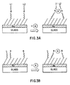
- Possible subunit constructs include:
- the support is a metal, i.e. a solid, rigid, substrate selected from materials known in the art for affinity ligand immobilization. Criteria for such supports are known; for example, the support should be free from extraneous ion-exchange sites, should not promote non-specific binding, should be mechanically strong enough for the contemplated application, should be biologically and chemically inert, and be adapted for ligand immobilization.
- the support should also be stable under reaction conditions (e.g. for ligand immobilization) and in its intended environment for use.
- Useful supports for module immobilization in general comprise organic polymers, metals, semiconductors, and ceramics.
- the support may comprise a mixture of these materials, such as an organic polymer layer bonded to an inorganic layer to provide attachment sites for certain affinity modules, or a nonconducting oxide layer on a metallic or other substrate.
- the affinity support will comprise a relatively thin film or composite film as further described infra.
- the affinity support is comprised of a metal.
- Modular engineering of reagentless analyte sensor units includes the manufacture of a minimum combination of two modules having the separate functions of (a) analyte binding affinity (affinity module) and (b) recognition-responsive signalling (reporter module).
- the sensor units are engineered into the assembly so that the binding event between the receptor and analyte affects the signalling properties of the reporter module sufficiently to permit detection of the event.
- the modular design concept is attractive because it is useful with a variety of receptors and their target analytes. Thus far, however, it has been only used to generate indicators for binding of heavy metal ions in solution.
- the modular assemblies of the invention are prepared by covalent or non-covalent attachment of component modules, to a solid affinity support or substrate comprised of a metal. They are solid-state assemblies, herein distinguished from other affinity matrices having affinity supports comprising fluid, free-standing membranes such as lipid bilayers, vesicles and Langmuir films.
- the solid state assemblies of the invention are engineered for sufficient structural stability so that direct or indirect perturbation of the reporter module to cause signal changes reliably reflects complex formation rather than extraneous events.
- the supports comprise known materials used in the art for the immobilization of affinity ligands.
- the support is comprised of a metal.
- SAMs self-assembled monolayers
- polymeric brushes and grafted polymers materials including self-assembled monolayers (SAMs); polymeric brushes and grafted polymers.
- Materials that are ordered assemblies e.g., SAMs of alkylthiols on noble metals and some semiconductors, of silanes on oxides, or of carboxylic acids on basic oxides, polymer brushes and certain grafted polymers, are herein distinguished from those that are normally relatively disordered such as polymer gels and surface-adsorbed insoluble polymers.
- SAMs of alkylthiols on noble metals and some semiconductors, of silanes on oxides, or of carboxylic acids on basic oxides, polymer brushes and certain grafted polymers are herein distinguished from those that are normally relatively disordered such as polymer gels and surface-adsorbed insoluble polymers.
- There have been only a few reports on the use of such assemblies for reagentless chemical sensing Motesharei, K
- Luminescence-Based Sensor units A number of virtues make measurement of changes in luminescence (e.g., fluorescence, phosphorescence) properties a desirable method of transduction in affinity-based sensor units. Under appropriate conditions, luminescence spectroscopy can be used to probe extremely low concentrations of analyte; changes in fluorescence spectra and lifetimes can even be detected from a single molecule (Ambrose, W.P.; Goodwin, P.M.; Martin, J.C.; Keller, R.A. "Alterations of Single Molecule Fluorescence Lifetimes in Near-Field Optical microscopy," Science 265 : 364, 1994).
- luminescence e.g., fluorescence, phosphorescence
- Luminescence can essentially function as an amplification mechanism, as a single luminophor can be subjected to multiple cycles of excitation and emission, each of which reflects the binding state of a receptor with which the luminophor is associated.
- Other useful properties of luminescence include the fact that intensity of absorbance and emission at various wavelengths, luminescence polarization, and excited state lifetime, are all properties of the luminophor that are, in general, sensitive to the chemical and electrical environment of the luminophor. Hence, these properties can all be used to advantage in a multi-measurement analysis of the binding state of a receptor with which the luminophor is associated for real time monitoring of analyte.
- the present inventions are based on modular assemblies that incorporate affinity and reporter modules selected and disposed on the support so that binding of an analyte to the receptor (affinity) module results in one or more changes in the architecture (order) of the molecular assembly to which the luminescent or other properties of the reporter module are sensitive.
- Examples of such changes are: (1) a change in the structure of the modular assembly resulting in a change in the average distance between the luminescent centers of a luminophor module and a solid substrate having appropriate dielectric properties (e.g., n and k ) so that the original luminescent properties of the luminophor are changed upon analyte binding; (1) (b) a change in the structure of the assembly resulting in a change in the average distance between an electroactive reporter probe, e.g., a redox reporter such as viologen or a redox enzyme such as horseradish peroxide; (2) a change in the structure of the modular assembly so that the transport properties of quenchers such as oxygen are modified upon analyte binding; (3) a change of the structure of modular assemblies so that the luminescent properties of a luminophor reporter are indirectly affected by effector modules built into the modular assembly such as excimer couples, collisional quenchers and resonance energy transfer donors or acceptors; (4) a change of the structure of modular assemblies
- PET photoinduced electron transfer
- Prasanna de Silva, A.; Gunnlaugsson, T.; Rice, T.E. "Recent Evolution of Luminescent Photoinduced Electron Transfer Sensors," Analyst 121 : 1759, 1996; Fabbrizzi, L.; Licchelli, M.; Pallavicini, P.; Sacchi, D.; Taglietti, A. "Sensing of Transition Metals Through Fluorescence Quenching or enhancement: A Review,” Analyst 121 : 1763, 1996, incorporated herein by reference).
- Such mechanisms permit the generalization of the present affinity matrices to permit the facile detection of a host of analytes.
- a particularly significant aspect of the invention is the enablement of binary or higher order modularity of function provided by the inventive modular concept.
- modules performing additional functions may also be included.
- an anti-fouling module comprising, for example, polyethylene glycol or a highly-hydrated polysaccharide can be included to eliminate biofouling of the affinity matrix.
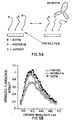
- a value of 1.0 on the X-axis corresponds to a separation distance of -65 nm. This separation is in the midrange of thicknesses for the thin film molecular assemblies envisioned here.
- the components of the complex index of refraction ( n and k) of the substrate can be used, together with the separation distance and the orientation of the fluor or phosphor relative to the substrate surface and the roughness of the substrate surface, to estimate how strongly the surface will influence the lifetime and emission intensity of the reporter (Chen, H.C.; Frank, C.W., "Fluorescence Probe Studies of Self-Assembled Monolayer Films," Langmuir 1 : 1791, 1991).
- Several new types of synthetic molecular assemblies are described below that can take advantage of these phenomena in the transduction of binding of an analyte to a modular assembly.
- a synthetic (bio)organic assembly is formed either directly on a metallic surface (e.g., gold, silver), on an nonconducting oxide on a metallic surface or on any other solid support (e.g., semiconductor, oxide, organic polymer, the support of the invention being a metal) that can function either as a spacer from the metallic surface or, if designed with the appropriate dielectric properties as known in the art, also as the module that perturbs the signalling properties of the reporter module.
- the following Examples demonstrate transduction by direct measurement of fluorescence lifetime, or by measurement of fluorescence intensity and/or polarization that may correlate with fluorescence lifetime. Very thin films of metals or other materials that are transparent to excitation and emitted light can be formed on supports for compact sensing platforms based, for example, on evanescent wave excitation.
- luminescent reporters In addition to luminescent reporters, other reporters sensitive to changes in their distance from a metallic or other support may be employed. These include redox reporters such as electroactive chemical and biochemical compounds, e.g., ferrocene, viologen, and enzymes that catalyze redox reactions.
- redox reporters such as electroactive chemical and biochemical compounds, e.g., ferrocene, viologen, and enzymes that catalyze redox reactions.
- Reagentless transduction can also be based on the use of quenchers capable of quenching excited states of a luminophor in the sample or sensing medium (e.g., O 2 in air or dissolved in water).
- quenchers capable of quenching excited states of a luminophor in the sample or sensing medium (e.g., O 2 in air or dissolved in water).
- binding of the analyte to a receptor results in a change in the modular assembly which inhibits the transport of a molecular quencher (e.g., O 2 ) to the luminophor.
- Transport (e.g., diffusion) inhibition can be affected by, inter alia:
- the modular incorporation of receptor and luminophor modules are disposed in close proximity in the assembly to cause a change in the photoemission characteristics of a luminescent reporter upon binding of the analyte to the receptor.
- Typical luminophor properties affected by the analyte include photoinduced charge transfer, resonance energy transfer, and changes in the local dielectric environment of the luminescent probe.
Landscapes
- Health & Medical Sciences (AREA)
- Life Sciences & Earth Sciences (AREA)
- Engineering & Computer Science (AREA)
- Immunology (AREA)
- Chemical & Material Sciences (AREA)
- Molecular Biology (AREA)
- Biomedical Technology (AREA)
- Hematology (AREA)
- Urology & Nephrology (AREA)
- Physics & Mathematics (AREA)
- General Physics & Mathematics (AREA)
- Cell Biology (AREA)
- Food Science & Technology (AREA)
- Medicinal Chemistry (AREA)
- Biotechnology (AREA)
- Analytical Chemistry (AREA)
- Biochemistry (AREA)
- General Health & Medical Sciences (AREA)
- Pathology (AREA)
- Microbiology (AREA)
- Nanotechnology (AREA)
- Composite Materials (AREA)
- Materials Engineering (AREA)
- Crystallography & Structural Chemistry (AREA)
- Condensed Matter Physics & Semiconductors (AREA)
- Inorganic Chemistry (AREA)
- Investigating Or Analysing Materials By The Use Of Chemical Reactions (AREA)
- Investigating, Analyzing Materials By Fluorescence Or Luminescence (AREA)
- Investigating Or Analysing Biological Materials (AREA)
- Investigating Or Analyzing Non-Biological Materials By The Use Of Chemical Means (AREA)
Claims (24)
- Modulares System zur Affinitätstrennung eines Analyten von einer Probe, aufweisend:einen Affinitätsträger, der aus einem Metall besteht; undmindestens eine Sensoreinheit aufweisend:ein Affinitätsmodul, wobei das Affinitätsmodul Bindungsaffinität für den Analyten hat; undein Signal-kompetentes Indikatormodul, wobei das Signal-kompetente Indikatormodul direkt oder indirekt auf das Signal der Komplexbildung zwischen dem Affinitätsmodul und dem Analyten anspricht, wobei das Signal-kompetente Indikatormodul auf dem Affinitätsträger immobilisiert ist;und wobei das Signal-kompetente Indikatormodul dergestalt von dem Affinitätsträger beabstandet ist, dass die Komplexbildung eine Veränderung des Abstands zwischen dem Signal-kompetenten Indikatormodul und dem Affinitätsträger bewirkt.
- Modulares System nach Anspruch 1, bei dem das Indikatormodul indirekt auf die Komplexbildung anspricht, und bei dem das modulare System außerdem ein Effektormodul, das mit dem Affinitätsträger in Verbindung steht, um das Ansprechsignal auf die Komplexbildung des Indikatormoduls zu vermitteln, aufweist.
- Modulares System nach Anspruch 1, bei dem das Indikatormodul einen Lumineszenzstrahler aufweist.
- Modulares System nach Anspruch 2, bei dem das Indikatormodul einen Lumineszenzstrahler aufweist.
- Modulares System nach Anspruch 3, bei dem das Ansprechsignal des Indikatormoduls direkt durch Analyt-Bindung herbeigeführt wird.
- Modulares System nach Anspruch 5, bei dem das Ansprechsignal durch Löschen durch Stoß, durch fotoinduzierte Elektronenübertragung oder durch Resonanzenergieübertragung herbeigeführt wird.
- Modulares System nach Anspruch 4, bei dem das Ansprechsignal des Indikatormoduls durch Verschiebung dieses Moduls relativ zu dem Effektormodul bei Komplexbildung herbeigeführt wird.
- Modulares System nach Anspruch 7, bei dem das Ansprechsignal durch eine Veränderung der dielektrischen Umgebung des Indikatormoduls herbeigeführt wird.
- Modulares System nach Anspruch 7, bei dem das Effektormodul einen metallischen Bestandteil aufweist.
- Modulares System nach Anspruch 1, bei dem das Affinitätsmodul und das Indikatormodul in beabstandeter Beziehung auf dem Träger immobilisiert sind.
- Modulares System nach Anspruch 1, bei dem das Affinitätsmodul an dem Träger befestigt ist.
- Modulares System nach Anspruch 1, bei dem das Affinitätsmodul an dem Träger befestigt und von dem Signal-kompetenten Indikatormodul beabstandet ist.
- Modulares System nach Anspruch 1, bei dem das Affinitätsmodul an dem Träger befestigt und mit dem Signal-kompetenten Indikatormodul verbunden ist.
- Modulares System nach Anspruch 1, bei dem das Signal-kompetente Indikatormodul dergestalt von dem Träger beabstandet ist, dass eine Fluoreszenz nicht gelöscht wird.
- Modulares System nach Anspruch 3, bei dem die Veränderung des Abstands zwischen dem Signal-kompetenten Indikatormodul und dem Träger von dem Lumineszenzzentrum des Lumineszenzstrahlers zu dem Träger gemessen wird.
- Modulares System nach Anspruch 4, bei dem die Veränderung des Abstands zwischen dem Signal-kompetenten Indikatormodul und dem Träger von dem Lumineszenzzentrum des Lumineszenzstrahlers zu dem Träger gemessen wird.
- Modulares System nach Anspruch 1, bei dem das Indikatormodul einen Elektrophor aufweist.
- Modulares System nach Anspruch 2, bei dem das Indikatormodul einen Elektrophor aufweist.
- Modulares System nach Anspruch 17 oder 18, bei dem der Elektrophor ein Redox-Indikator ist.
- Modulares System nach Anspruch 19, bei dem der Redox-Indikator Viologen ist.
- Modulares System nach Anspruch 17 oder 18, bei dem der Elektrophor ein Redox-Enzym ist.
- Modulares System nach Anspruch 21, bei dem das Redox-Enzym Meerrettichperoxidase ist.
- Analysekit zum Nachweis eines Analyten, aufweisend das modulare System nach einem der Ansprüche 1 bis 22.
- Verfahren zum Nachweisen eines Analyten in einer Probe, bei dem das modulare System nach einem der Ansprüche 1 bis 22 der Probe ausgesetzt wird und ein Signal von dem Indikatormodul nachgewiesen wird.
Applications Claiming Priority (3)
| Application Number | Priority Date | Filing Date | Title |
|---|---|---|---|
| US4350197P | 1997-04-11 | 1997-04-11 | |
| US43501P | 1997-04-11 | ||
| PCT/US1998/006871 WO1998047001A1 (en) | 1997-04-11 | 1998-04-10 | Modular assembly for reagentless affinity separation and detection of analyte |
Publications (3)
| Publication Number | Publication Date |
|---|---|
| EP0988549A1 EP0988549A1 (de) | 2000-03-29 |
| EP0988549A4 EP0988549A4 (de) | 2002-09-04 |
| EP0988549B1 true EP0988549B1 (de) | 2005-03-02 |
Family
ID=21927477
Family Applications (1)
| Application Number | Title | Priority Date | Filing Date |
|---|---|---|---|
| EP98918027A Expired - Lifetime EP0988549B1 (de) | 1997-04-11 | 1998-04-10 | Modulare anordnung zur reagenzlosen affinitätsseparation und detektion von analyten |
Country Status (6)
| Country | Link |
|---|---|
| US (1) | US6660532B1 (de) |
| EP (1) | EP0988549B1 (de) |
| AT (1) | ATE290211T1 (de) |
| CA (1) | CA2285957A1 (de) |
| DE (1) | DE69829182T2 (de) |
| WO (1) | WO1998047001A1 (de) |
Families Citing this family (6)
| Publication number | Priority date | Publication date | Assignee | Title |
|---|---|---|---|---|
| US20060160916A1 (en) * | 2004-08-13 | 2006-07-20 | Dyer Daniel J | Process for modifying substrates with grafted polymers |
| US20070141597A1 (en) * | 2005-10-25 | 2007-06-21 | Harmon H J | Biomimetic Biodetector of Toxins, Viruses, Bacteria, and Biological Factors |
| DE102005062003A1 (de) * | 2005-12-22 | 2007-06-28 | Endress + Hauser Conducta Gesellschaft für Mess- und Regeltechnik mbH + Co. KG | Vorrichtung und Verfahren zur Detektion und/oder quantitativen Messung eines Zielmediums |
| WO2009148651A1 (en) * | 2008-02-28 | 2009-12-10 | Board Of Regents, The University Of Texas System | Compositions and methods for detection of small molecules using dyes derivatized with analyte responsive receptors in a chemiluminescent assay |
| DE102014224449A1 (de) * | 2014-11-28 | 2016-06-02 | Forschungszentrum Jülich GmbH | Szintillationsdetektor mit hoher Zählrate |
| US20190361015A1 (en) * | 2017-01-23 | 2019-11-28 | University Of Louisville Research Foundation, Inc. | Electrically-Modulated Biosensors Using Electro-Active Waveguides |
Family Cites Families (16)
| Publication number | Priority date | Publication date | Assignee | Title |
|---|---|---|---|---|
| US5310687A (en) | 1984-10-31 | 1994-05-10 | Igen, Inc. | Luminescent metal chelate labels and means for detection |
| US4801726A (en) | 1986-04-15 | 1989-01-31 | Northeastern University | Repetitive hit-and-run immunoassay and stable support-analyte conjugates; applied to T-2 toxin |
| US5135876A (en) * | 1987-09-24 | 1992-08-04 | University Of Utah | Method and apparatus for the regulation of complex binding |
| US5229302A (en) * | 1988-03-29 | 1993-07-20 | Matsushita Electric Industrial Co., Ltd. | Fluorescence immunoassay method utilizing pseudo-antigens combined with fluorescent quenchers |
| US5268305A (en) * | 1989-06-15 | 1993-12-07 | Biocircuits Corporation | Multi-optical detection system |
| US5156810A (en) * | 1989-06-15 | 1992-10-20 | Biocircuits Corporation | Biosensors employing electrical, optical and mechanical signals |
| US5491097A (en) * | 1989-06-15 | 1996-02-13 | Biocircuits Corporation | Analyte detection with multilayered bioelectronic conductivity sensors |
| CA2024548C (en) * | 1989-09-05 | 2002-05-28 | David Issachar | Analyte specific chemical sensor |
| AU6753390A (en) * | 1989-10-02 | 1991-04-28 | University Of Michigan, The | Bioanalytical detection system |
| EP0476545B1 (de) * | 1990-09-14 | 1997-05-07 | Tosoh Corporation | Verfahren und Kit für Immunoassay |
| US5776672A (en) * | 1990-09-28 | 1998-07-07 | Kabushiki Kaisha Toshiba | Gene detection method |
| US5154890A (en) * | 1990-11-07 | 1992-10-13 | Hewlett-Packard Company | Fiber optic potassium ion sensor |
| US5914241A (en) * | 1993-01-19 | 1999-06-22 | Biosite Diagnostics, Inc. | Assays and kits for detecting analytes in the presence of cross-reacting substances |
| IL108726A (en) * | 1994-02-22 | 1999-12-31 | Yissum Res Dev Co | Electrobiochemical method and system for the determination of an analyte which is a member of a recognition pair in a liquid medium and electrodes therefor |
| US5624537A (en) | 1994-09-20 | 1997-04-29 | The University Of British Columbia - University-Industry Liaison Office | Biosensor and interface membrane |
| JPH11503005A (ja) | 1995-03-08 | 1999-03-23 | アクゾ ノーベル ナムローゼ フェンノートシャップ | 表面修飾されたアフィニティ分離膜 |
-
1998
- 1998-04-10 EP EP98918027A patent/EP0988549B1/de not_active Expired - Lifetime
- 1998-04-10 DE DE69829182T patent/DE69829182T2/de not_active Expired - Lifetime
- 1998-04-10 WO PCT/US1998/006871 patent/WO1998047001A1/en not_active Ceased
- 1998-04-10 AT AT98918027T patent/ATE290211T1/de not_active IP Right Cessation
- 1998-04-10 CA CA002285957A patent/CA2285957A1/en not_active Abandoned
-
1999
- 1999-04-10 US US09/402,682 patent/US6660532B1/en not_active Expired - Lifetime
Also Published As
| Publication number | Publication date |
|---|---|
| EP0988549A4 (de) | 2002-09-04 |
| DE69829182D1 (de) | 2005-04-07 |
| EP0988549A1 (de) | 2000-03-29 |
| US6660532B1 (en) | 2003-12-09 |
| DE69829182T2 (de) | 2005-12-29 |
| WO1998047001A1 (en) | 1998-10-22 |
| CA2285957A1 (en) | 1998-10-22 |
| ATE290211T1 (de) | 2005-03-15 |
Similar Documents
| Publication | Publication Date | Title |
|---|---|---|
| AU2001262994B2 (en) | Improvements to the fluorescent polymer-qtl approach to biosensing | |
| Holford et al. | Recent trends in antibody based sensors | |
| Pejcic et al. | The role of biosensors in the detection of emerging infectious diseases | |
| US5194393A (en) | Optical biosensor and method of use | |
| US7091049B2 (en) | Enhanced diffraction-based biosensor devices | |
| CA2024548C (en) | Analyte specific chemical sensor | |
| US7141369B2 (en) | Measuring cellular metabolism of immobilized cells | |
| AU2001262994A1 (en) | Improvements to the fluorescent polymer-QTL approach to biosensing | |
| Mastichiadis et al. | Simultaneous determination of pesticides using a four-band disposable optical capillary immunosensor | |
| US6790632B2 (en) | Membrane receptor reagent and assay | |
| Anis et al. | Reusable fiber optic immunosensor for rapid detection of imazethapyr herbicide | |
| Aoyagi et al. | Development of fluorescence change-based, reagent-less optic immunosensor | |
| EP2224241B1 (de) | Träger zur verwendung bei der analytmessung und verfahren zur herstellung davon | |
| EP0988549B1 (de) | Modulare anordnung zur reagenzlosen affinitätsseparation und detektion von analyten | |
| US8512966B2 (en) | Method for sensing a chemical | |
| US5314802A (en) | Light emission- or absorbance-based binding assays | |
| Bosch et al. | Optical chemical biosensors for high throughput screening of drugs | |
| Madou et al. | Immunosensors with commercial potential | |
| Demchenko | Basic principles | |
| CA2420743A1 (en) | Biosensor assay device and method | |
| Schäferling | Fluorescence‐based biosensors | |
| CN114486822A (zh) | 一种用fret技术检测抗原抗体相互作用的方法 | |
| JP3831759B2 (ja) | 抗梅毒トレポネーマ抗体の免疫分析方法及び免疫分析装置 | |
| Trojanowicz | Main concepts of chemical and biological sensing | |
| Thompson | Protein-based biosensors with polarization transduction |
Legal Events
| Date | Code | Title | Description |
|---|---|---|---|
| PUAI | Public reference made under article 153(3) epc to a published international application that has entered the european phase |
Free format text: ORIGINAL CODE: 0009012 |
|
| 17P | Request for examination filed |
Effective date: 19991013 |
|
| AK | Designated contracting states |
Kind code of ref document: A1 Designated state(s): AT BE CH DE DK ES FI FR GB GR IE IT LI LU MC NL PT SE |
|
| RIN1 | Information on inventor provided before grant (corrected) |
Inventor name: YAN,JUCHAO Inventor name: JAIN, RAVINDER, K. Inventor name: RABINOVICH, EMMANUIL Inventor name: OPPERMAN, KIMBERLY Inventor name: TENDER, LEONARD Inventor name: HAMPTON, PHILIP Inventor name: SKLAR, LARRY, A. Inventor name: LOPEZ, GABRIEL, P. |
|
| A4 | Supplementary search report drawn up and despatched |
Effective date: 20020718 |
|
| AK | Designated contracting states |
Kind code of ref document: A4 Designated state(s): AT BE CH DE DK ES FI FR GB GR IE IT LI LU MC NL PT SE |
|
| 17Q | First examination report despatched |
Effective date: 20030910 |
|
| GRAP | Despatch of communication of intention to grant a patent |
Free format text: ORIGINAL CODE: EPIDOSNIGR1 |
|
| GRAS | Grant fee paid |
Free format text: ORIGINAL CODE: EPIDOSNIGR3 |
|
| GRAA | (expected) grant |
Free format text: ORIGINAL CODE: 0009210 |
|
| AK | Designated contracting states |
Kind code of ref document: B1 Designated state(s): AT BE CH DE DK ES FI FR GB GR IE IT LI LU MC NL PT SE |
|
| PG25 | Lapsed in a contracting state [announced via postgrant information from national office to epo] |
Ref country code: NL Free format text: LAPSE BECAUSE OF FAILURE TO SUBMIT A TRANSLATION OF THE DESCRIPTION OR TO PAY THE FEE WITHIN THE PRESCRIBED TIME-LIMIT Effective date: 20050302 Ref country code: LI Free format text: LAPSE BECAUSE OF FAILURE TO SUBMIT A TRANSLATION OF THE DESCRIPTION OR TO PAY THE FEE WITHIN THE PRESCRIBED TIME-LIMIT Effective date: 20050302 Ref country code: IT Free format text: LAPSE BECAUSE OF FAILURE TO SUBMIT A TRANSLATION OF THE DESCRIPTION OR TO PAY THE FEE WITHIN THE PRE;WARNING: LAPSES OF ITALIAN PATENTS WITH EFFECTIVE DATE BEFORE 2007 MAY HAVE OCCURRED AT ANY TIME BEFORE 2007. THE CORRECT EFFECTIVE DATE MAY BE DIFFERENT FROM THE ONE RECORDED.SCRIBED TIME-LIMIT Effective date: 20050302 Ref country code: FI Free format text: LAPSE BECAUSE OF FAILURE TO SUBMIT A TRANSLATION OF THE DESCRIPTION OR TO PAY THE FEE WITHIN THE PRESCRIBED TIME-LIMIT Effective date: 20050302 Ref country code: CH Free format text: LAPSE BECAUSE OF FAILURE TO SUBMIT A TRANSLATION OF THE DESCRIPTION OR TO PAY THE FEE WITHIN THE PRESCRIBED TIME-LIMIT Effective date: 20050302 Ref country code: BE Free format text: LAPSE BECAUSE OF FAILURE TO SUBMIT A TRANSLATION OF THE DESCRIPTION OR TO PAY THE FEE WITHIN THE PRESCRIBED TIME-LIMIT Effective date: 20050302 Ref country code: AT Free format text: LAPSE BECAUSE OF FAILURE TO SUBMIT A TRANSLATION OF THE DESCRIPTION OR TO PAY THE FEE WITHIN THE PRESCRIBED TIME-LIMIT Effective date: 20050302 |
|
| REG | Reference to a national code |
Ref country code: GB Ref legal event code: FG4D |
|
| REG | Reference to a national code |
Ref country code: CH Ref legal event code: EP |
|
| REG | Reference to a national code |
Ref country code: IE Ref legal event code: FG4D |
|
| REF | Corresponds to: |
Ref document number: 69829182 Country of ref document: DE Date of ref document: 20050407 Kind code of ref document: P |
|
| PG25 | Lapsed in a contracting state [announced via postgrant information from national office to epo] |
Ref country code: LU Free format text: LAPSE BECAUSE OF NON-PAYMENT OF DUE FEES Effective date: 20050410 |
|
| PG25 | Lapsed in a contracting state [announced via postgrant information from national office to epo] |
Ref country code: IE Free format text: LAPSE BECAUSE OF NON-PAYMENT OF DUE FEES Effective date: 20050411 |
|
| PG25 | Lapsed in a contracting state [announced via postgrant information from national office to epo] |
Ref country code: MC Free format text: LAPSE BECAUSE OF NON-PAYMENT OF DUE FEES Effective date: 20050430 |
|
| PG25 | Lapsed in a contracting state [announced via postgrant information from national office to epo] |
Ref country code: GR Free format text: LAPSE BECAUSE OF FAILURE TO SUBMIT A TRANSLATION OF THE DESCRIPTION OR TO PAY THE FEE WITHIN THE PRESCRIBED TIME-LIMIT Effective date: 20050602 Ref country code: DK Free format text: LAPSE BECAUSE OF FAILURE TO SUBMIT A TRANSLATION OF THE DESCRIPTION OR TO PAY THE FEE WITHIN THE PRESCRIBED TIME-LIMIT Effective date: 20050602 |
|
| PG25 | Lapsed in a contracting state [announced via postgrant information from national office to epo] |
Ref country code: ES Free format text: LAPSE BECAUSE OF FAILURE TO SUBMIT A TRANSLATION OF THE DESCRIPTION OR TO PAY THE FEE WITHIN THE PRESCRIBED TIME-LIMIT Effective date: 20050613 |
|
| PG25 | Lapsed in a contracting state [announced via postgrant information from national office to epo] |
Ref country code: PT Free format text: LAPSE BECAUSE OF FAILURE TO SUBMIT A TRANSLATION OF THE DESCRIPTION OR TO PAY THE FEE WITHIN THE PRESCRIBED TIME-LIMIT Effective date: 20050817 |
|
| NLV1 | Nl: lapsed or annulled due to failure to fulfill the requirements of art. 29p and 29m of the patents act | ||
| REG | Reference to a national code |
Ref country code: CH Ref legal event code: PL |
|
| PLBE | No opposition filed within time limit |
Free format text: ORIGINAL CODE: 0009261 |
|
| STAA | Information on the status of an ep patent application or granted ep patent |
Free format text: STATUS: NO OPPOSITION FILED WITHIN TIME LIMIT |
|
| ET | Fr: translation filed | ||
| 26N | No opposition filed |
Effective date: 20051205 |
|
| PG25 | Lapsed in a contracting state [announced via postgrant information from national office to epo] |
Ref country code: SE Free format text: LAPSE BECAUSE OF FAILURE TO SUBMIT A TRANSLATION OF THE DESCRIPTION OR TO PAY THE FEE WITHIN THE PRESCRIBED TIME-LIMIT Effective date: 20050602 |
|
| PGFP | Annual fee paid to national office [announced via postgrant information from national office to epo] |
Ref country code: FR Payment date: 20100506 Year of fee payment: 13 |
|
| PGFP | Annual fee paid to national office [announced via postgrant information from national office to epo] |
Ref country code: GB Payment date: 20100421 Year of fee payment: 13 Ref country code: DE Payment date: 20100629 Year of fee payment: 13 |
|
| REG | Reference to a national code |
Ref country code: DE Ref legal event code: R119 Ref document number: 69829182 Country of ref document: DE |
|
| REG | Reference to a national code |
Ref country code: DE Ref legal event code: R119 Ref document number: 69829182 Country of ref document: DE |
|
| GBPC | Gb: european patent ceased through non-payment of renewal fee |
Effective date: 20110410 |
|
| REG | Reference to a national code |
Ref country code: FR Ref legal event code: ST Effective date: 20111230 |
|
| PG25 | Lapsed in a contracting state [announced via postgrant information from national office to epo] |
Ref country code: FR Free format text: LAPSE BECAUSE OF NON-PAYMENT OF DUE FEES Effective date: 20110502 |
|
| PG25 | Lapsed in a contracting state [announced via postgrant information from national office to epo] |
Ref country code: GB Free format text: LAPSE BECAUSE OF NON-PAYMENT OF DUE FEES Effective date: 20110410 |
|
| PG25 | Lapsed in a contracting state [announced via postgrant information from national office to epo] |
Ref country code: DE Free format text: LAPSE BECAUSE OF NON-PAYMENT OF DUE FEES Effective date: 20111031 |