EP0988696B1 - Filtre de resonateur a mode transversal - Google Patents
Filtre de resonateur a mode transversal Download PDFInfo
- Publication number
- EP0988696B1 EP0988696B1 EP98934853A EP98934853A EP0988696B1 EP 0988696 B1 EP0988696 B1 EP 0988696B1 EP 98934853 A EP98934853 A EP 98934853A EP 98934853 A EP98934853 A EP 98934853A EP 0988696 B1 EP0988696 B1 EP 0988696B1
- Authority
- EP
- European Patent Office
- Prior art keywords
- converter
- filter
- input
- mode resonator
- overlap
- Prior art date
- Legal status (The legal status is an assumption and is not a legal conclusion. Google has not performed a legal analysis and makes no representation as to the accuracy of the status listed.)
- Expired - Lifetime
Links
- 238000003780 insertion Methods 0.000 description 3
- 230000037431 insertion Effects 0.000 description 3
- 238000004904 shortening Methods 0.000 description 2
- 240000006829 Ficus sundaica Species 0.000 description 1
- 230000006978 adaptation Effects 0.000 description 1
- 230000000694 effects Effects 0.000 description 1
- 239000007787 solid Substances 0.000 description 1
- 238000010897 surface acoustic wave method Methods 0.000 description 1
Images

Classifications
-
- H—ELECTRICITY
- H03—ELECTRONIC CIRCUITRY
- H03H—IMPEDANCE NETWORKS, e.g. RESONANT CIRCUITS; RESONATORS
- H03H9/00—Networks comprising electromechanical or electro-acoustic elements; Electromechanical resonators
- H03H9/46—Filters
- H03H9/64—Filters using surface acoustic waves
- H03H9/6423—Means for obtaining a particular transfer characteristic
- H03H9/6433—Coupled resonator filters
-
- H—ELECTRICITY
- H03—ELECTRONIC CIRCUITRY
- H03H—IMPEDANCE NETWORKS, e.g. RESONANT CIRCUITS; RESONATORS
- H03H9/00—Networks comprising electromechanical or electro-acoustic elements; Electromechanical resonators
- H03H9/46—Filters
- H03H9/64—Filters using surface acoustic waves
- H03H9/6423—Means for obtaining a particular transfer characteristic
- H03H9/6433—Coupled resonator filters
- H03H9/644—Coupled resonator filters having two acoustic tracks
- H03H9/6456—Coupled resonator filters having two acoustic tracks being electrically coupled
- H03H9/6459—Coupled resonator filters having two acoustic tracks being electrically coupled via one connecting electrode
- H03H9/6463—Coupled resonator filters having two acoustic tracks being electrically coupled via one connecting electrode the tracks being electrically cascaded
-
- H—ELECTRICITY
- H03—ELECTRONIC CIRCUITRY
- H03H—IMPEDANCE NETWORKS, e.g. RESONANT CIRCUITS; RESONATORS
- H03H9/00—Networks comprising electromechanical or electro-acoustic elements; Electromechanical resonators
- H03H9/02—Details
- H03H9/125—Driving means, e.g. electrodes, coils
- H03H9/145—Driving means, e.g. electrodes, coils for networks using surface acoustic waves
- H03H9/14517—Means for weighting
- H03H9/1452—Means for weighting by finger overlap length, apodisation
-
- H—ELECTRICITY
- H03—ELECTRONIC CIRCUITRY
- H03H—IMPEDANCE NETWORKS, e.g. RESONANT CIRCUITS; RESONATORS
- H03H9/00—Networks comprising electromechanical or electro-acoustic elements; Electromechanical resonators
- H03H9/02—Details
- H03H9/125—Driving means, e.g. electrodes, coils
- H03H9/145—Driving means, e.g. electrodes, coils for networks using surface acoustic waves
- H03H9/14517—Means for weighting
- H03H9/14526—Finger withdrawal
Definitions
- the present invention relates to a transversal mode locked Surface wave resonator filter, also in the following Transverse mode resonator filter called after the generic term of claim 1.
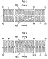
- Resonator filters are, for example, from "1992, Ultrasonics Symposium ", pages 39 to 43. Its basic structure is shown schematically in Fig. 5.
- the resonator filter contains two resonators RES, each with an interdigital transducer W9 or W10 with uniform normal finger structure and two each on opposite sides of the interdigital converters W9 and W10 short-circuit reflectors arranged R1, R1 or R3, R3.
- the reflectors are over a common busbar 2 electrically and acoustically with each other coupled, which acts as a ground rail and via ground connections is electrically accessible.
- the interdigital converter W9 is the Filter input and the interdigital converter W10 the filter output assigned. All transversal mode resonator filters implemented so far - also this well-known filter identical input and output converters and therefore identical Input and output impedances.
- EP 0 772 293 A1 discloses a transversal mode-locked Surface wave resonator filter known, which consists of two acoustically coupled tracks is built using a transducer is replaced by a split converter that has a higher impedance than a normal finger converter.
- the present invention has set itself the task of to fix the disadvantage of the known filters, i.e. to show a way through the filter with accordingly adapted different input and output impedances created can be.
- FIG. 1 filled up by additional reflectors R2, R2 and thus increases the reflector effect.
- the input converter can be structured in the same way, whereby to avoid the same input and output impedances only to pay attention to different active finger structures is.
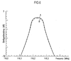
- FIG. 6 shows the insertion loss plotted against the frequency for the known transverse mode resonator filter according to Fig. 5 - s. the solid curve A -, and for the filter 1 with compared to the filter of FIG. 5 on the half length shortened output converter W2 - s. the dashed Curve B.
- the difference occurring in the Insertion loss of approx. 1 dB is due to circuit-related losses in the electrical adjustment network.
- the impedance of the output converter W2 is higher by a factor of 4 than the input impedance.
- the omission weighting sees blind fingers 4, i.e. overlap-free and therefore largely electrical and acoustic inactive fingers.
- the filter shows another possibility of omission weighting 3, whose input converter with normal finger structure with W5 and its output converter with W6.
- the Measure of the active finger overlap of the output transducer W6 is here by arranging an appropriate number controlled by blind fingers 1.
- the invention is also based on Input converter applicable.
- Input converter applicable.
- simultaneous use on both transducers if desired, to avoid same input and output impedances only on one pay attention to different structural changes.
- the invention is not limited to transverse mode resonator filters with only one input and output converter. It can also several filters of this type connected in series or in parallel his.
- the filter design according to Figures 2, 4 is otherwise suitable to additionally improve the close selection of the filter.
Landscapes
- Physics & Mathematics (AREA)
- Acoustics & Sound (AREA)
- Surface Acoustic Wave Elements And Circuit Networks Thereof (AREA)
- Piezo-Electric Or Mechanical Vibrators, Or Delay Or Filter Circuits (AREA)
- Control Of Motors That Do Not Use Commutators (AREA)
Claims (5)
- Filtre de résonateur à mode transversal, ayant deux convertisseurs d'entrée et de sortie à structure de doigts normale, identiques, disposés suivant deux pistes couplées acoustiquement et interposés entre des réflecteurs, dans lequel l'impédance du convertisseur d'entrée ou du convertisseur de sortie est augmentée,
caractérisé en ce que l'impédance du convertisseur d'entrée ou du convertisseur de sortie est augmentée, par rapport à une structure digitée normale uniforme, par réduction du chevauchement actif des doigts d'origine, par l'une des mesures a) à c) :a) la longueur d'un transducteur (W2 - figure 1) est diminuée ;b) le chevauchement actif des doigts d'un convertisseur (W4 - figure 2 ; W6 - figure 3) est réduit par pondération d'omission ;c) le chevauchement actif des doigts d'un convertisseur (W8 - figure 4) est réduit par pondération de chevauchement. - Filtre suivant la revendication 1, dans lequel conformément à la mesure a), l'espace libre formé par la longueur diminuée du convertisseur est empli par des réflecteurs (R2, R2 - figure 1) supplémentaires.
- Filtre suivant la revendication 1, dans lequel la pondération d'omission est réalisée en partie par des doigts (1 - figure 3) aveugles.
- Filtre suivant l'une des revendications 1 à 3, dans lequel plusieurs filtres de résonateurs à mode transversal sont montés en série.
- Filtre suivant l'une des revendications 1 à 3, dans lequel plusieurs filtres de résonateurs à mode transversal sont montés en parallèle.
Applications Claiming Priority (3)
| Application Number | Priority Date | Filing Date | Title |
|---|---|---|---|
| DE19724255A DE19724255C2 (de) | 1997-06-09 | 1997-06-09 | Transversalmodenresonatorfilter |
| DE19724255 | 1997-06-09 | ||
| PCT/DE1998/001505 WO1998057427A1 (fr) | 1997-06-09 | 1998-06-03 | Filtre de resonateur a mode transversal |
Publications (2)
| Publication Number | Publication Date |
|---|---|
| EP0988696A1 EP0988696A1 (fr) | 2000-03-29 |
| EP0988696B1 true EP0988696B1 (fr) | 2002-09-04 |
Family
ID=7831922
Family Applications (1)
| Application Number | Title | Priority Date | Filing Date |
|---|---|---|---|
| EP98934853A Expired - Lifetime EP0988696B1 (fr) | 1997-06-09 | 1998-06-03 | Filtre de resonateur a mode transversal |
Country Status (8)
| Country | Link |
|---|---|
| US (1) | US6342824B1 (fr) |
| EP (1) | EP0988696B1 (fr) |
| JP (1) | JP2002508901A (fr) |
| KR (1) | KR20010013604A (fr) |
| CN (1) | CN1124684C (fr) |
| CA (1) | CA2294167A1 (fr) |
| DE (2) | DE19724255C2 (fr) |
| WO (1) | WO1998057427A1 (fr) |
Families Citing this family (3)
| Publication number | Priority date | Publication date | Assignee | Title |
|---|---|---|---|---|
| DE19900326C2 (de) * | 1999-01-07 | 2001-06-07 | Epcos Ag | Transversalmodenresonatorfilteranordnung |
| JP3622758B2 (ja) * | 2003-03-28 | 2005-02-23 | 松下電器産業株式会社 | 弾性表面波共振器、弾性表面波フィルタ、及びアンテナ共用器 |
| CN118589839B (zh) * | 2024-08-06 | 2024-12-13 | 深圳市微源半导体股份有限公司 | 死区时间控制电路、电压变换器及开关电源 |
Citations (1)
| Publication number | Priority date | Publication date | Assignee | Title |
|---|---|---|---|---|
| EP0786681A1 (fr) * | 1995-08-14 | 1997-07-30 | Sumitomo Osaka Cement Co., Ltd. | Isolateur optique independant de la polarisation |
Family Cites Families (12)
| Publication number | Priority date | Publication date | Assignee | Title |
|---|---|---|---|---|
| JPS57119509A (en) * | 1981-01-19 | 1982-07-26 | Toshiba Corp | Surface acoustic wave resonator |
| DE3130154A1 (de) * | 1981-07-30 | 1983-02-17 | Siemens Ag | Oberflaechenwellen-anordnung mit integriertem anpassungsnetzwerk |
| JP2927107B2 (ja) * | 1992-07-17 | 1999-07-28 | 株式会社大真空 | 横結合2重モード弾性表面波フィルタ |
| JP3654920B2 (ja) * | 1993-06-18 | 2005-06-02 | 株式会社東芝 | 多段接続弾性表面波多重モードフィルタ |
| DE4431612C2 (de) * | 1993-09-06 | 1998-07-16 | Sanyo Electric Co | Akustisches Oberflächenwellenfilter |
| DE69424737T2 (de) * | 1993-10-08 | 2000-09-28 | Matsushita Electric Ind Co Ltd | Akustisches Oberflächenwellenfilter |
| JPH08125490A (ja) * | 1994-10-25 | 1996-05-17 | Sanyo Electric Co Ltd | 多重モード弾性表面波フィルター |
| JPH08139566A (ja) * | 1994-11-09 | 1996-05-31 | Nec Corp | 弾性表面波フィルタ |
| JPH08213876A (ja) * | 1995-02-03 | 1996-08-20 | Matsushita Electric Ind Co Ltd | 横結合多重モードsawフィルタ |
| DE19516903C2 (de) * | 1995-05-09 | 1997-03-06 | Dresden Ev Inst Festkoerper | Resonatorfilter |
| GB2306821B (en) * | 1995-11-03 | 2000-05-31 | Advanced Saw Prod Sa | Electro-acoustic device |
| EP0921636B1 (fr) * | 1996-05-23 | 2007-04-04 | Matsushita Electric Industrial Co., Ltd. | Filtre à ondes acoustiques de surface et filtre à ondes acoustiques de surface à plusieurs étages |
-
1997
- 1997-06-09 DE DE19724255A patent/DE19724255C2/de not_active Expired - Fee Related
-
1998
- 1998-06-03 KR KR19997011614A patent/KR20010013604A/ko not_active Withdrawn
- 1998-06-03 DE DE59805424T patent/DE59805424D1/de not_active Expired - Lifetime
- 1998-06-03 CN CN98805989.4A patent/CN1124684C/zh not_active Expired - Lifetime
- 1998-06-03 JP JP50129199A patent/JP2002508901A/ja active Pending
- 1998-06-03 EP EP98934853A patent/EP0988696B1/fr not_active Expired - Lifetime
- 1998-06-03 WO PCT/DE1998/001505 patent/WO1998057427A1/fr not_active Ceased
- 1998-06-03 CA CA002294167A patent/CA2294167A1/fr not_active Abandoned
-
1999
- 1999-12-09 US US09/456,710 patent/US6342824B1/en not_active Expired - Lifetime
Patent Citations (1)
| Publication number | Priority date | Publication date | Assignee | Title |
|---|---|---|---|---|
| EP0786681A1 (fr) * | 1995-08-14 | 1997-07-30 | Sumitomo Osaka Cement Co., Ltd. | Isolateur optique independant de la polarisation |
Also Published As
| Publication number | Publication date |
|---|---|
| JP2002508901A (ja) | 2002-03-19 |
| DE59805424D1 (de) | 2002-10-10 |
| CA2294167A1 (fr) | 1998-12-17 |
| CN1124684C (zh) | 2003-10-15 |
| CN1260086A (zh) | 2000-07-12 |
| DE19724255C2 (de) | 1999-10-21 |
| US6342824B1 (en) | 2002-01-29 |
| EP0988696A1 (fr) | 2000-03-29 |
| KR20010013604A (ko) | 2001-02-26 |
| WO1998057427A1 (fr) | 1998-12-17 |
| DE19724255A1 (de) | 1998-12-10 |
Similar Documents
| Publication | Publication Date | Title |
|---|---|---|
| DE69316786T2 (de) | Elastische Oberflächenwellenfilter | |
| EP1125364B1 (fr) | Systeme a ondes de surface presentant au moins deux structures a ondes de surface | |
| DE69412424T2 (de) | Akustisches Oberflächenwellenfilter | |
| DE69620524T2 (de) | Oberflächenwellenfilter | |
| DE112009002361B4 (de) | Filtervorrichtung für elastische Wellen | |
| DE69827187T2 (de) | Akustische Oberflächenwellenanordnung mit Nahfeldkopplung und differentiellen Ein- und Ausgängen | |
| EP1205026A1 (fr) | Filtre a ondes de surface bimode a symetrie amelioree et eventuellement affaiblissement hors bande ameliore | |
| DE10343296B4 (de) | Oberflächenwellenbauelement und Kommunitkationsvorrichtung, die dasselbe umfasst | |
| EP0687063B1 (fr) | Filtre électrique fonctionnant avec des ondes acoustiques | |
| EP1256172B1 (fr) | Filtre a ondes acoustiques de surface dote d'elements de reactance | |
| WO1991009465A1 (fr) | Filtre-reflecteur d'ondes superficielles | |
| DE19924933B4 (de) | Oberflächenwellenbauelement | |
| DE10152917B4 (de) | Oberflächenwellenfilter und Kommunikationsvorrichtung, die dasselbe enthält | |
| DE4013214C2 (de) | Akustisches Oberflächenwellenfilter | |
| EP0988696B1 (fr) | Filtre de resonateur a mode transversal | |
| WO1990003690A1 (fr) | Filtre a ondes de surface | |
| EP0204168B1 (fr) | Filtre électrique à ondes acoustiques | |
| DE10122007B4 (de) | Akustisches Oberflächenfilter | |
| EP1266450B1 (fr) | Filtre de resonateur couple en mode transversal a encombrement reduit | |
| EP1342317A1 (fr) | Filtre a resonateurs a couplage transversal | |
| DE2635192A1 (de) | Akustsche oberflaechenwellenanordnung | |
| EP0436566B1 (fr) | Transducteur a ponderation par omission pour filtres a ondes de surface | |
| DE19900326C2 (de) | Transversalmodenresonatorfilteranordnung | |
| DE19726594A1 (de) | Dualmode-Oberflächenwellenfilter | |
| DE102019113299A1 (de) | Akustische Verzögerungskomponente |
Legal Events
| Date | Code | Title | Description |
|---|---|---|---|
| PUAI | Public reference made under article 153(3) epc to a published international application that has entered the european phase |
Free format text: ORIGINAL CODE: 0009012 |
|
| 17P | Request for examination filed |
Effective date: 19991206 |
|
| AK | Designated contracting states |
Kind code of ref document: A1 Designated state(s): CH DE FR GB LI |
|
| RIN1 | Information on inventor provided before grant (corrected) |
Inventor name: BAUERNSCHMITT, ULRICH Inventor name: BAIER, THOMAS |
|
| 17Q | First examination report despatched |
Effective date: 20000713 |
|
| GRAG | Despatch of communication of intention to grant |
Free format text: ORIGINAL CODE: EPIDOS AGRA |
|
| GRAG | Despatch of communication of intention to grant |
Free format text: ORIGINAL CODE: EPIDOS AGRA |
|
| GRAH | Despatch of communication of intention to grant a patent |
Free format text: ORIGINAL CODE: EPIDOS IGRA |
|
| GRAH | Despatch of communication of intention to grant a patent |
Free format text: ORIGINAL CODE: EPIDOS IGRA |
|
| GRAA | (expected) grant |
Free format text: ORIGINAL CODE: 0009210 |
|
| AK | Designated contracting states |
Kind code of ref document: B1 Designated state(s): CH DE FR GB LI |
|
| REG | Reference to a national code |
Ref country code: GB Ref legal event code: FG4D Free format text: NOT ENGLISH |
|
| REG | Reference to a national code |
Ref country code: CH Ref legal event code: EP |
|
| GBT | Gb: translation of ep patent filed (gb section 77(6)(a)/1977) |
Effective date: 20020904 |
|
| REG | Reference to a national code |
Ref country code: CH Ref legal event code: NV Representative=s name: E. BLUM & CO. PATENTANWAELTE |
|
| REF | Corresponds to: |
Ref document number: 59805424 Country of ref document: DE Date of ref document: 20021010 |
|
| ET | Fr: translation filed | ||
| PG25 | Lapsed in a contracting state [announced via postgrant information from national office to epo] |
Ref country code: GB Free format text: LAPSE BECAUSE OF NON-PAYMENT OF DUE FEES Effective date: 20030603 |
|
| PG25 | Lapsed in a contracting state [announced via postgrant information from national office to epo] |
Ref country code: LI Free format text: LAPSE BECAUSE OF NON-PAYMENT OF DUE FEES Effective date: 20030630 Ref country code: CH Free format text: LAPSE BECAUSE OF NON-PAYMENT OF DUE FEES Effective date: 20030630 |
|
| PLBE | No opposition filed within time limit |
Free format text: ORIGINAL CODE: 0009261 |
|
| STAA | Information on the status of an ep patent application or granted ep patent |
Free format text: STATUS: NO OPPOSITION FILED WITHIN TIME LIMIT |
|
| RAP2 | Party data changed (patent owner data changed or rights of a patent transferred) |
Owner name: EPCOS AG |
|
| 26N | No opposition filed |
Effective date: 20030605 |
|
| GBPC | Gb: european patent ceased through non-payment of renewal fee |
Effective date: 20030603 |
|
| REG | Reference to a national code |
Ref country code: CH Ref legal event code: PL |
|
| PG25 | Lapsed in a contracting state [announced via postgrant information from national office to epo] |
Ref country code: FR Free format text: LAPSE BECAUSE OF NON-PAYMENT OF DUE FEES Effective date: 20040227 |
|
| REG | Reference to a national code |
Ref country code: FR Ref legal event code: ST |
|
| REG | Reference to a national code |
Ref country code: DE Ref legal event code: R082 Ref document number: 59805424 Country of ref document: DE Representative=s name: BARDEHLE PAGENBERG PARTNERSCHAFT MBB PATENTANW, DE Ref country code: DE Ref legal event code: R081 Ref document number: 59805424 Country of ref document: DE Owner name: SNAPTRACK, INC., SAN DIEGO, US Free format text: FORMER OWNER: EPCOS AG, 81669 MUENCHEN, DE |
|
| PGFP | Annual fee paid to national office [announced via postgrant information from national office to epo] |
Ref country code: DE Payment date: 20170623 Year of fee payment: 20 |
|
| REG | Reference to a national code |
Ref country code: DE Ref legal event code: R071 Ref document number: 59805424 Country of ref document: DE |