EP0988720B1 - Procede et systeme destines a un reseau cellulaire - Google Patents
Procede et systeme destines a un reseau cellulaire Download PDFInfo
- Publication number
- EP0988720B1 EP0988720B1 EP98930031A EP98930031A EP0988720B1 EP 0988720 B1 EP0988720 B1 EP 0988720B1 EP 98930031 A EP98930031 A EP 98930031A EP 98930031 A EP98930031 A EP 98930031A EP 0988720 B1 EP0988720 B1 EP 0988720B1
- Authority
- EP
- European Patent Office
- Prior art keywords
- radio base
- cells
- base station
- sequence
- base stations
- Prior art date
- Legal status (The legal status is an assumption and is not a legal conclusion. Google has not performed a legal analysis and makes no representation as to the accuracy of the status listed.)
- Expired - Lifetime
Links
Images




Classifications
-
- H—ELECTRICITY
- H04—ELECTRIC COMMUNICATION TECHNIQUE
- H04B—TRANSMISSION
- H04B7/00—Radio transmission systems, i.e. using radiation field
- H04B7/24—Radio transmission systems, i.e. using radiation field for communication between two or more posts
- H04B7/26—Radio transmission systems, i.e. using radiation field for communication between two or more posts at least one of which is mobile
- H04B7/2662—Arrangements for Wireless System Synchronisation
- H04B7/2671—Arrangements for Wireless Time-Division Multiple Access [TDMA] System Synchronisation
- H04B7/2678—Time synchronisation
- H04B7/2687—Inter base stations synchronisation
- H04B7/2693—Centralised synchronisation, i.e. using external universal time reference, e.g. by using a global positioning system [GPS] or by distributing time reference over the wireline network
-
- H—ELECTRICITY
- H04—ELECTRIC COMMUNICATION TECHNIQUE
- H04W—WIRELESS COMMUNICATION NETWORKS
- H04W56/00—Synchronisation arrangements
- H04W56/001—Synchronization between nodes
-
- H—ELECTRICITY
- H04—ELECTRIC COMMUNICATION TECHNIQUE
- H04W—WIRELESS COMMUNICATION NETWORKS
- H04W56/00—Synchronisation arrangements
- H04W56/0055—Synchronisation arrangements determining timing error of reception due to propagation delay
- H04W56/0065—Synchronisation arrangements determining timing error of reception due to propagation delay using measurement of signal travel time
- H04W56/007—Open loop measurement
- H04W56/0075—Open loop measurement based on arrival time vs. expected arrival time
- H04W56/0085—Open loop measurement based on arrival time vs. expected arrival time detecting a given structure in the signal
Definitions
- the present invention generally relates to a method and a system, respectively, for counteracting interference between cells in a cellular mobile radio system including a plurality of radio base stations and mobile radio stations.
- the radio base stations are of the kind using, as units of transmission, bursts organized in groups, each group forming a frame of the type used by a Time Division Multiple Access TDMA system, and each burst containing a known sequence of data bits.
- At least two of the radio base stations are supposed to be co-channel radio base stations employing a same frequency.
- the invention also relates to a radio base station for use in a cellular mobile radio system of the kind mentioned.
- US 5,206,855 discloses transmission of messages in a system using several frequencies. The messages are transmitted sequentially in such a way that messages from one cell are not transmitted simultaneously with transmission from another cell.
- US 4,972,507 relates to a method for transmitting data between the base station and the user unit in a mobile telephony system. All user units in a cell are interrogated by the base station transmitting an interrogation signal. The user units respond by sending a short message where each unit has a unique delay for avoiding that messages interfere.
- US 5,473,612 discloses how to decrease the risk for erroneous detection of a data packet in a radio communication system.
- the described invention is based upon the fact that packets from different stations have different delay.
- the synchronization sequence is searched in a time window corresponding to the delay of said station.
- WO 95/35,601 discloses a method for minimizing interference from surrounding cells by using four different frequencies and directional antennas.
- WO 95/17,048 discloses a radio telephony system where "co-channel interference" is reduced by assigning channels dependent on the position of the mobile unit and controlling the output power so as to make mobiles located within border areas to send with a lower power.
- WO 94/30,024 describes a method for synchronizing two base stations in a CDMA system.
- the purpose of the synchronizing is to obtain so-called "macro diversity”.
- the relative interference ratio expressed as C/I, where C is the Carrier level and I is the Interference level, may vary a lot between calls.
- C changes with the mobile station position relative to the base station, with the amount of obstacles between them, etc.; I changes depending on whether the frequency is being used by another call in some nearby cell, and it also varies according to the distance to the interfering source, its level, etc.
- burst A basic concept of the GSM transmission on the radio path is that the unit of transmission, called burst, is a series of e.g. about 150 modulated bits.
- the GSM bursts are organized in groups of 8, such a group being referred to as a TDMA frame (TDMA - Time Division Multiple Access). Bursts have a finite duration, and occupy a finite part of the radio spectrum. They are sent in time and frequency windows, or slots. Precisely, the central frequencies of the slots are positioned every 200 kHz within the system frequency band (FDMA aspect), and they recur in time every 0,577 ms, or more exactly, every 15/26 ms (TDMA aspect). All slot time limits regarding different carrier frequencies are simultaneous in a given cell.
- FDMA aspect system frequency band
- TDMA aspect system frequency band
- the amplitude of transmission rises from a starting value of 0 to its nominal value.
- the signal phase is modulated to transmit a packet of bits. After that, the amplitude decreases until it reaches 0.
- the packet of bits used to modulate the signal phase of a burst includes a training sequence besides the variable part of the information, plus "0" bits at each end.
- the training sequence is a sequence of 26 bits known by the receiver.
- the signal resulting from the transmission of this training sequence allows the receiver to determine very precisely the position of the useful signal inside a reception time slot, and to have an idea of the distortion caused by transmission. These informations are of prime importance to obtain good demodulation performance.
- One of the purposes of using training sequences is to obtain equalization.
- the eight training sequences have been chosen for the special shape of their autocorrelation function, which is meant to ease some demodulation techniques.
- one of the issues is normally the frequency planning, i.e. the distance between frequency reuse, and how to place different frequencies for fulfilling the capacity and coverage requirements.
- One limiting parameter for the planning is the distance to the closest co-channel interferer, i.e. the distance to the cells employing the same set of frequencies.
- the problem occurs, if the co-sequence interfering base stations have a timing of the TDMA-frame, which involves that the training sequence from the co-sequence interferer overlaps the training sequence from the desired transmitter.
- this object is achieved by an inventive method and apparatus, respectively, providing at least two co-channel radio base stations with a time reference signal and with a radio base station specific time offset differing between the co-channel radio base stations by at least a predetermined value which prevents known sequences in desired signals and known sequences in interfering signals from overlapping in a disturbing way at reception.
- the time reference signal and the radio base station specific offset are used for the timing of sending bursts downlink from the co-channel radio base stations towards mobile radio stations.
- a radio base station comprising means for receiving the time reference signal, means for storing the radio base station specific time offset, and means for making use of the time reference signal and the radio base station specific offset for the timing of sending bursts downlink from the co-channel radio base stations towards mobile radio stations.
- An advantage obtained with the present invention is that the offset allows the receiver to receive the wanted line of sight signal and also reflected signals if an equalizer is used in the receiver while rejecting co-channel signals because they have a time offset above a predetermined value.
- a further advantage is the reduced disturbance. This may be used either for obtaining better quality i.e. improved carrier-to-interference ratio C/I, or increased traffic handling capacity.
- Fig. 1 illustrates the beam patterns of an antenna array in a cellular TDMA network when a strong co-sequence interference is present between two of the network's cells, i.e. two cells employing the same frequency and the same training sequence.
- Fig. 1 shows a GSM network part structure including five cells 102, 104, 106, 108 and 110, the cells 102 and 110 being separated from each other by the cells 104, 106 and 108.
- the base stations of cells 102 and 110 are indicated at 112 and 114.
- the cells 102 and 110 are using the same training sequence, as well as employing the same frequencies. It is therefore the question of possible co-sequence interference between the base stations 112 and 114, as will be explained below.
- the base stations of the cells 104, 106 and 108 have training sequences being different both mutually and with respect to the cells 102 and 110.
- a mobile station 116 located in the cell 102 emits bursts to the network received by the base station 112 and resulting in a small narrow beam pattern 118 being formed towards the mobile station 116.
- another mobile station 120 located in the co-sequence interfering cell 110 also emits bursts to the network received by the base station 114 and resulting in a beam pattern 122.
- the bursts of the mobile station 120 are also, however, intercepted by the base station 112 and perceived as if they were desired bursts from the user 116.
- the base station 112 therefore perceives the co-sequence interference as a desired signal component and will amplify the interfering signal from the mobile station 120, this being indicated by a beam pattern 124.
- Fig. 2 illustrates a situation in which a co-sequence interference signal could be percepted as a desired signal component when received in the same receiving unit, e.g. the base station 112 in Fig. 1. More particularly, there are shown three received bursts 200, 202 and 204, respectively.
- the bursts 200 and 202 are supposed to be a desired signal and a co-sequence interference signal, respectively, as e.g. arriving from the mobile stations 116 and 120, respectively, as discussed above with reference to Fig. 1.
- the burst 204 is supposed to be an alternative co-sequence interference signal and has been introduced in Fig. 2 for the purpose of further explanation.
- the three signals partially overlap along a time axis, not shown.
- each burst has two packets of information surrounding a training sequence.
- the information packets and training sequence of the burst 200 are indicated at 206, 208 and 210, respectively.
- the bursts 202 and 204 are similarily structured as shown.
- the misalignment between the training sequence 210 and that of the co-sequence interfering burst 204 is denoted ⁇ t 204 .
- Fig. 2 there is also shown a region 212 extending on both sides of the left hand end of the training sequence 210. This region 212 indicates a critical misalignment denoted ⁇ t critical to each side of the left hand end of the training sequence 210.
- a misalignment such as the misalignments ⁇ t 202 and ⁇ t 204 between the training sequences of the co-sequence interfering signals 202 and 204, has to be more than the value ⁇ t critical to ensure that co-sequence effects will not occur.
- ⁇ t 202 is less than ⁇ t critical
- ⁇ t 204 is greater than ⁇ t critical , meaning that co-sequence effects may occur in the case of the burst 202 but not in the case of the burst 204.
- T s designates a symbol time to be used henceforth when explaining different aspects of the invention.
- a base station can start to receive the bursts of a co-sequence interference signal instead of the desired signal.
- the timing functionality of the base station will synchronize on the wrong mobile station in the cases where the co-sequence interference is stronger than the signal from the desired mobile.
- the diversity combining, equalization and smart antenna combining algorithms will amplify the interference, as the base station receives the desired training sequence from the interference.
- uplink transmission from a mobile station MS towards a base station BTS
- downlink transmission from a BTS towards an MS
- TSC training sequence code
- the burst timing in the uplink direction is derived from the downlink direction by a delay of 3 burst periods, where each burst period has a value of 15/26 ms. This delay of nominally 3 burst periods is constant throughout GSM.
- the delay between sent and received bursts of the mobile station is affected by the propagation delays which, even at the speed of light, are not negligible compared to the burst duration (the round-trip delay between an MS and a BTS 30 km apart is 200 ⁇ s).
- the mobile station advances its emission relatively to its reception by a time compensating the propagation delay. This value is called the timing advance, or TA, which will be used as a parameter in connection with describing the invention further below.
- the exact shift between downlink and uplink as seen by the mobile station is then 3 burst periods minus the timing advance.
- the timing advance value can be computed by the BTS, and is then provided to the mobile station through signalling.
- the interference problem can be disregarded. The same is the case if the training sequences do not overlap in time. The behaviour of the timing and the power will now be studied.
- the structure of the training sequence is furthermore of importance.
- the training sequence consists of 3 different data entities A, B and C, arranged in five blocks in a way so as to have good autocorrelation properties.
- the structure of the training sequence starts with a first block 302 of the data entity A followed by blocks 304, 306, 308 and 310 of the data entities B, C, A and B, respectively.
- Fig. 4 illustrates three important parameters.
- two cells are indicated at 402 and 404, and their respective base stations at 406 and 408.
- the cells 402 and 404 are supposed to be co-sequence interfering.
- a first parameter is the distance d ⁇ t d , indicated by double arrow 410, between the base stations 406 and 408.
- a second parameter is timing advance TA as described above.
- a third parameter is the "radius" r ⁇ t r of the cell 404, indicated by double arrow 412.
- the propagation time t r between the base station 408 and the cell border is assumed to be half of the maximum timing advance TA value.
- the timing advance TA lets the interfering signal come earlier to the co-sequence cell.
- the misalignment ⁇ t is the same in base station 406 uplink and mobile station 416 downlink and amounts to t d - 2t r in the example shown in Fig. 4, wherein the mobile 416 is supposed to be located near a border facing cell 402, and described more closely below.
- the TA thus makes the co-sequence signal active earlier to the base station 406 in the cell 402 that uses the same training sequence.
- d 10 km
- r 4 km
- a problem will arise when the disturbing mobile 416 is close to the cell border facing the cell 402 as indicated in Fig. 4.
- the second important parameter, which has to be examined to show whether there is a problem, is the sensitivity when the co-sequence power is low, i.e. the path loss between co-sequence cells might remove the problem.
- MRC Maximum Ratio Combining
- IRC Interference Rejection Combining
- the first simulation evaluates the MRC algorithm on sector antennas, which corresponds to the diversity system operating in GSM today.
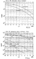
- Fig. 5 is a curve diagram showing the MRC algorithm on two branches, as a typical diversity base station works today.
- the upper curve indicates co-sequence interference and the lower one indicates co-channel interference.
- the performance is approximately 4 dB worse in the case of co-sequence interference.
- the delay ⁇ t is 0 T s .
- the path loss between co-sequence cells is significantly larger than the path loss between neighbouring co-channel cells. If the path loss of a co-sequence signal to the desired carrier is 4 dB more than that of a co-channel signal, the disturbing effect of co-sequence will be the same as that of co-channel. It might also be expected that path loss will reduce co-sequence interference significantly.
- Fig. 6 indicates that the co-sequence interference 601 requires in the order of 30 dB better C/I than the ordinary co-channel interference 602. This indicates that even though the path loss is larger for co-sequence interference than for co-channel interference, the co-sequence interference can still degrade the system performance significantly.
- Fig. 6 furthermore shows the degradation for different time offsets ⁇ t between the base station and the co-sequence interfering mobile station.
- the offset was 2 km corresponding to 1.8 T s .
- this involves an extreme degradation of the performance.
- the above described problems of having co-sequence interference can be dealt with by putting constraints on the frequency planning.
- the co-sequence cells have to be separated sufficiently in order to obtain sufficient path loss or timing misalignment.
- the co-sequence can also be reduced by increasing the frequency reuse distance.
- this solution will degrade capacity.
- co-channel radio base stations using the same training sequences, or those having different training sequences but cross-correlation effects are provided with a time reference signal being a synchronizing signal or a time reference from another co-channel radio base station.
- Each co-channel radio base station is furthermore provided with a radio base station specific time offset differing between the co-channel radio base stations by at least a predetermined value which prevents known sequences in desired signals and known sequences in interfering signals from overlapping in a disturbing way at reception.
- the time reference signal and the radio base station specific offset are used for the timing of sending bursts downlink from the co-channel radio base stations towards mobile radio stations.
- the employed algorithms in the network are evaluated, e.g. by simulation, in order to determine the base station specific time offsets.
- Fig. 6 indicates for instance that when the time offset is 4 Ts or more, the co-sequence interference problem is significantly reduced.
- the optimization procedure is iterative, corresponding to ordinary frequency planning.
- the base stations are first synchronized and then an individual time-delay is inserted on each base station, in order to eliminate/reduce the co-sequence problem.
- the synchronization can be performed e.g. through a PCM link or by GPS.
- the wide tolerance of the synchronization accuracy allows a cheap/easy synchronization method.
- the offsets are adjusted at the individual base station by monitoring correlated interference.
- Fig. 7 there are two co-sequence cells x and y, indicated at 702 and 704, respectively. There is a distance d, indicated by double arrow 705, between the co-sequence cells x and y.
- the distance d is a first parameter to be used in a geometrical procedure to be described later, and defines the propagation time between the cells.
- the cell x has a radius r x , indicated by double arrow 706, and a base station B x , indicated at 708.
- the cell y has a radius r y , indicated by double arrow 710, and a base station B y , indicated at 712.
- the radii r x and r y are a second parameter to be used in the geometrical procedure.
- a synchronization functionality for synchronizing the base stations 708 and 712, indicated by arrows 716 and 718, respectively.
- a functionality indicated by a respective block 720 and 722, for adding a respective offset parameter t off(x) and t off(y) , as well as the tolerance ⁇ t sync of the synchronization functionality 714, to the respective base stations 708 and 712.
- the offset parameters t off(x) and t off(y) are used as adjustment means for avoiding the co-sequence interference phenomenon.
- the tolerance ⁇ t sync takes into account e.g. different lengths of cables between block 714 and the radio base stations 708 and 712.
- the network avoids critical overlap of equal training sequences.
- One co-sequence layer can be planned independently of all others. The planning procedure will therefore be illustrated for one layer only in an example to be described later on.
- the task is to adjust t off for each cell with respect to the critical co-sequence cells, so that ⁇ t never is in a critical region.
- a graphical method will be described here.
- the above eight equations are included in a graphical overview according to Fig. 8, which can be used for the adjustment of the t off parameters and illustrates the influence of the different parameters.
- the x-axis is the adjustable t off parameter and the y-axis is the resulting misalignment, ⁇ t.
- the width of the horizontal bar 802 covering the x-axis defines the critical region ⁇ t critical , where overlapping will cause problems.
- the slanted bars of Fig. 8 show the timing relationship to the neighbouring cells.
- One bar is drawn for each disturbing signal, i.e. there are 4 bars B y ⁇ M x (804), B x ⁇ M y (806) , M y ⁇ B x (808) and M x ⁇ B y (810) as appears from the above equations.
- the thickness of each of the bars depends on the possible variation, i.e the maximum propagation time in the cell containing the mobile, t r , and the tolerance of the synchronization signal, ⁇ t sync .
- the difference between min ( ⁇ t) and max ( ⁇ t) is indicated at 812 as 2t r +2 ⁇ t sync .
- the geometrical adjustment procedure can be summarized as follows, step by step.
- This part of the procedure consists of the ordinary planning, i.e.:
- TSC-layer The cells with particular training sequence codes TSCs and equal frequencies are identified and treated independently. Each group of cells with equal TSC will be referred to as a TSC-layer.
- Fig. 6 indicates that an examplary IRC algorithm for uplink combining is very sensitive to co-sequence interference, and therefore requires a high path loss. A path loss of 30 dB more than the co-channel interference, would make the effects from co-sequence interference comparable to co-channel effects.
- Each cell is linked to a group of cells, which are potential co-sequence interfering cells. Find:
- Tier is a ring of cells to be explained below.
- the procedure results in a network design, which ensures that all co-sequence interferers with too small path loss compared to the path loss of the co-channel interferers, will be shifted in time with respect to each other by a minimum of 5 T s .
- the example is based on the following assumptions:
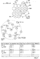
- Fig. 9 shows the presumed cellular network structure with all frequencies reused in all cells, and only the 8 different training sequences being used to distinguish between signals from different cells.
- the digit within each cell corresponds to a TSC-number used in the cell as indicated at 901 by arrows pointing to two cells having the TSC-numbers 0 and 2, respectively.
- the Figure also indicates two adjacent clusters 902 and 904 of cells, the borders of which are brought out by thick lines, and which each contain 8 cells of equal size among which the 8 possible TCS-numbers are distributed. In the whole network structure, the 8 training sequences are distributed in similar clusters.
- Step A corresponds to the conventional planning of frequencies and cell dimensions.
- step B it is found by measurements/simulations that the critical overlapping region is -5Ts ⁇ ⁇ t ⁇ +5Ts.
- step C the cells with the same training sequence number are grouped together, into 8 different TSC-layers.
- the clustering of sequences corresponds to the ordinary frequency clustering, and the expression "tier” is therefore reused as "co-sequence tier" in the case of co-sequence planning.
- Fig. 10 shows the geometry of one TSC layer, for TSC 3, similar to the geometry of a frequency reuse clustering, there being a first tier 1002 containing cells B-G, surrounding cell A, and a second tier 1004 of the TSC 3 layer.
- step D it is assumed that if a cell is so far away that the path loss is larger than 30 dB, its influence is insignificant as compared to ordinary co-channel interference. Power control and path loss have to be taken into account, when considering which cells have a sufficiently high power level to cause co-sequence problems.
- the first co-sequence tier is causing co-sequence problems, and the second one is attenuated sufficiently due to path loss.
- step E is to provide an overview in the form of a table or database, schematically illustrated by Fig. 11.
- the table according to Fig. 11 in the first column contains all cells in the network which are to be time offset relative each other. Each of these cells is linked to a number of potential co-sequence interferers and their parameters, appearing in the second and further columns, respectively.
- the table/database thus contains all the parameters in a linked way so that an iterative optimization program can start with row one, and go through the table until a solution is found. As the cellular structure is homogeneous, the table with linked cells also becomes homogeneous.
- Step F starts the time adjustment procedure, following the table according to Fig. 11.
- the time offset for cell A, t off(A) is chosen to 10 T S . In Fig. 12, the reason for this appears from vertical lines 1202 and 1204 extending through crossings where the slanted bars 1206 and 1208 meet the horizontal bar 1210, in the same way as has been explained for Fig. 8.
- the adjustment of cell A is now finished, and cell A is avoiding all risks of co-sequence interference from co-sequence tier 1.
- the next step is then to adjust cell B to all cells in its first co-sequence tier, this being illustrated by the graph according to Fig. 13.
- Slanted bars 1302 and 1304 indicate possible ⁇ t's for cells C, G, ... and slanted bars 1306 and 1308 indicate ⁇ t's for cell A.
- the crossings between bars 1302, 1304, 1306 and 1308, on the one hand, and horizontal bar 1310, on the other hand, in this graph indicate the possible adjustment of the time offset for cell B, t off(B), in the same way as has been explained above with reference to Fig. 8.
- the co-sequence cell A has already been adjusted and is therefore shifted in the graph, as indicated by the location of bars 1306 and 1308.
- Cell A is in cell B's first co-sequence tier and the time offset t off(B) for cell B has to be higher than 20 T s or less than -10 T s as indicated by vertical lines 1312 and 1314 extending through the crossings where the bar 1306 and the bar 1304, respectively, meet the horizontal bar 1310.
- the next step is to adjust the time offset t off(C) for cell C.
- the graph in Fig. 13 it can be seen that as much as 16 cells can be adjusted with respect to each other. In this example it is only necessary to adjust 3 cells to each other, as only the first co-sequence tier is taken into account.
- the cell structure in this example has been homogeneous, since all cells are supposed to have the same dimensions. If this is changed, it will only involve some minor differences between the individual cells in the graphs. If d for example is increased with 1.1 km this will only correspond to adding one symbol time to ⁇ t. There has furthermore been included a tolerance, ⁇ t sync , on the synchronization unit of ⁇ 1 T s . Furthermore, ⁇ t critical has been set to be within the region [-5 Ts; +5 Ts], which probably is an overshoot as indicated in Fig. 6, where ⁇ t isn't that critical for the values of 4 and 5 T s .
- the timing of the network is preferably optimized by setting up a cost function, as a function of time overlap and/or performance degradation.
- co-sequence interference has been discussed that can arise between co-channel cells having the same training sequence.
- the invention in this case is how to remove correlation effects from an undesired co-sequence interfering source. Problems with co-sequence interference can appear when tight frequency schemes are used, simultaneously using techniques exploiting correlation effects of the received signals. However, correlation problems can in addition occur due to the ordinary co-channel interference. The reason for the appearance of these degradations is that the different training sequences in GSM often are highly correlated.
- the present invention which so far has been described in connection with removing effects caused by co-sequence interference, can also be used successfully for removing undesired cross-correlation effects caused by ordinary co-channel interference.
- the geometrical adjustment procedure using steps A-F described above can also be used for removing undesired cross-correlation effects caused by disturbing co-channel interference.
- co-channel interferences in combination with training sequences with disturbing cross-correlation effects should also be adjusted in time to avoid overlapping in receiving units.
- the undesired overlapping region, referred to in Fig. 8 as ⁇ t critical can be different for different pairs of training sequences.
- the critical misalignments have to be found independen tly for different training sequences, i.e. there is a ⁇ t critical(x/y) , where x is the number of the desired training sequence, and y is the number of the interfering training sequence.
- the table shown in Fig. 14 provides an example of found critical regions.
- the desired training sequence is supposed to be No. 0, as appears from the first term within brackets in all lines of the table.
- the interfering training sequence is indicated to be No. 0
- compare the last term within the brackets the co-sequence interference is shown to have the same critical region as in the earlier examples, namely -5 T s ⁇ ⁇ t ⁇ +5 T s .
- a group of potentially disturbing cells should be identified based on the size of the propagation loss.
- Fig. 15 shows an example of a cellular network structure in which the cells that are together bounded by thicker lines all may contribute with a sufficiently high power to cause correlation problems.
- the cell indicated at 1502 has the desired training sequence 0, whereas the cell indicated at 1504 has the co-sequence interference training sequence 0.
- modified step D the group identified in modified step C should be limited to cells having undesired correlation effects.
- Fig. 16 illustrating the same cellular network structure as in Fig. 15, these cells are the co-sequence cell 1504 and a co-channel cell 1602 having training sequence number 1 and indicated in line 2 in the Table of Fig. 14.
- step E the geometrical parameters of the network should be found as described.
- step F adjustment of time offsets between co-sequence cells is performed.
- the cells are adjusted one by one with respect to the potentially disturbing cells found in modified step D.
- the adjustment can be performed with the same geometrical method as already described, however with different critical regions for different interfering cells.
- Fig. 17 schematically illustrates a radio base station 1700 for use in a cellular mobile radio system according to the invention of the kind described above.
- Fig. 17 block 1702 indicates a switching unit being connected, indicated by arrow 1704, to a network interface, and to a local bus 1706.
- the switching unit 1702 includes a function, indicated by block 1708, for receiving a time reference signal, such as a synchronization signal from the network or a base station time reference from an antenna interface.
- a timing unit for receiving the time reference signal from the time reference receiving function 1708.
- the timing unit 1710 also includes a store, indicated by block 1714, for storing a radio base station specific time offset of the kind that has been explained and described earlier with reference to Figs. 7-16. As has been explained, this time offset differs between co-channel radio base stations located in the same cellular mobile radio base system by at least a predetermined value which prevents known sequences in desired signals and known sequences in interfering signals from overlapping in a disturbing way at reception.
- the time offset is received by the store 1714 via the switching unit 1702 and transferred to the timing generator 1712. Via a timing bus 1716, the time reference signal and the radio base station specific offset are received by transceivers 1718 communicating with the local bus 1706.
- the transceivers 1718 use the time reference signal and the radio base station specific offset for the timing of sending bursts downlink towards mobile radio stations via combiners and splitters, indicated by a common block 1720, and an antenna interface, the connection to which being indicated by a double arrow 1722.
Landscapes
- Engineering & Computer Science (AREA)
- Computer Networks & Wireless Communication (AREA)
- Signal Processing (AREA)
- Radar, Positioning & Navigation (AREA)
- Remote Sensing (AREA)
- Mobile Radio Communication Systems (AREA)
Claims (17)
- Procédé de lutte contre les interférences, destiné à être utilisé dans un système radiocellulaire mobile comprenant une pluralité de stations de base radio et de stations mobiles radio,
lesdites stations de base radio utilisant, comme unités d'émission, des rafales organisées en groupes, chaque groupe formant une trame du type de celles utilisées par un système AMRT (Accès multiple à répartition dans le temps), et chaque rafale contenant une séquence connue de bits de données,
au moins deux des stations de base radio étant des stations de base radio partageant le même canal et employant la même fréquence,
ledit procédé comprenant les étapes consistant à :fournir aux stations de base radio partageant le même canal un signal de référence de temps qui est un signal de synchronisation ou une référence de temps provenant d'une autre station de base radio partageant le même canal,fournir à chaque station de base radio partageant le même canal un décalage de temps spécifique à la station de base radio qui diffère d'au moins une valeur prédéterminée entre les stations de base radio partageant le même canal, ce qui empêche des séquences connues dans les signaux souhaités et des séquences connues dans des signaux interférents de se superposer d'une manière gênante à la réception,utiliser dans chaque station de base radio partageant le même canal le signal de référence de temps et le décalage spécifique à la station de base radio pour la synchronisation des émissions de rafales sur la liaison descendante entre les stations de base radio partageant le même canal et des stations mobiles radio. - Procédé selon la revendication 1, dans lequel les étapes de fourniture d'un signal de référence de temps et de décalages de temps spécifiques aux stations de base radio comprend les étapes élémentaires consistant à :identifier dans ledit système radiocellulaire mobile des cellules ayant des stations de base radio partageant le même canal, dans lesquelles il existe un risque qu'une station mobile radio partageant le même canal, dans l'une desdites cellules, arrive en visibilité d'une station de base radio partageant le même canal dans une autre desdites cellules,synchroniser, à l'aide dudit signal de référence de temps, lesdites stations de base radio partageant le même canal desdites cellules identifiées tout en fournissant dans chaque station de base radio partageant le même canal ledit décalage de temps spécifique à la station de base radio, qui est une fraction de la durée d'une rafale, mais qui est suffisamment long pour éviter que des séquences connues dans les signaux souhaités et des séquences connues dans des signaux interférents ne se superposent de manière perturbatrice à la réception.
- Procédé selon la revendication 2, dans lequel l'étape d'identification comprend l'identification de cellules partageant la même séquence, qui emploient la même séquence connue, ce qui fait que ledit problème d'interférence est un problème d'interférence de coséquence.
- Procédé selon la revendication 3, dans lequel l'étape d'identification comprend le regroupement des cellules partageant la même séquence, en des couches qui ne comprennent que des cellules ayant la même séquence connue, et l'étude dudit risque séparément pour chacune des couches.
- Procédé selon l'une quelconque des revendications 2 à 4, comprenant l'étape consistant à ignorer dans chacune des couches les cellules qui ont un niveau de puissance qui est trop faible pour causer ledit problème d'interférence.
- Procédé selon la revendication 4 ou 5, comprenant l'étape consistant à déterminer successivement, pour chacune des couches, le décalage de temps nécessaire de chaque station de base radio partageant le même canal, tout en prenant en considération les décalages de temps éventuellement déjà déterminés pour d'autres stations de base radio partageant le même canal.
- Procédé selon la revendication 6, comprenant l'emploi comme paramètres, dans ladite étape de détermination successive,
de la distance entre des cellules partageant la même séquence,
des rayons des cellules,
de l'imprécision de la synchronisation, qui contribue à des variations dans les temps synchronisés. - Procédé selon l'une quelconque des revendications 1 à 7, comprenant les étapes consistant à simuler des perturbations et à utiliser les résultats de cette simulation pour déterminer les décalages de temps spécifiques aux stations de base radio.
- Système radiocellulaire mobile comprenant une pluralité de stations de base radio et de stations mobiles radio,
lesdites stations de base radio utilisant, comme unités d'émission, des rafales organisées en groupes, chaque groupe formant une trame du type de celles utilisées par un système AMRT (Accès multiple à répartition dans le temps), et chaque rafale contenant une séquence connue de bits de données,
au moins deux des stations de base radio étant des stations de base radio partageant le même canal et employant la même fréquence,
ledit système comprenant en outre :un moyen destiné à fournir aux stations de base radio partageant le même canal un signal de référence de temps qui est un signal de synchronisation ou une référence de temps provenant d'une autre station de base radio partageant le même canal,un moyen destiné à fournir à chaque station de base radio partageant le même canal un décalage de temps spécifique à la station de base radio, qui diffère d'au moins une valeur prédéterminée entre les stations de base radio partageant le même canal, ce qui empêche des séquences connues dans les signaux souhaités et des séquences connues dans des signaux interférents de se superposer d'une manière gênante à la réception,un moyen destiné à permettre d'utiliser dans chaque station de base radio partageant le même canal le signal de référence de temps et le décalage spécifique à la station de base radio pour la synchronisation des émissions de rafales sur la liaison descendante entre les stations de base radio partageant le même canal et des stations mobiles radio. - Système selon la revendication 9, dans lequel le moyen destiné à fournir un signal de référence de temps et des décalages de temps spécifiques aux stations de base radio comprend :un moyen destiné à identifier dans ledit système radiocellulaire mobile des cellules ayant des stations de base radio partageant le même canal, dans lesquelles il existe un risque qu'une station mobile radio partageant le même canal, dans l'une desdites cellules, arrive en visibilité d'une station de base radio partageant le même canal dans une autre desdites cellules,un moyen destiné à synchroniser, à l'aide dudit signal de référence de temps, lesdites stations de base radio partageant le même canal desdites cellules identifiées tout en fournissant dans chaque station de base radio partageant le même canal ledit décalage de temps spécifique à la station de base radio, qui est une fraction de la durée d'une rafale, mais qui est suffisamment long pour éviter que des séquences connues dans les signaux souhaités et des séquences connues dans des signaux interférents ne se superposent de manière perturbatrice à la réception.
- Système selon la revendication 10, dans lequel le moyen destiné à identifier comprend un moyen destiné à identifier des cellules partageant la même séquence, qui emploient la même séquence connue, ce qui fait que ledit problème d'interférence est un problème d'interférence de coséquence.
- Système selon la revendication 11, dans lequel Le moyen destiné à identifier comprend un moyen destiné à regrouper les cellules partageant la même séquence en des couches qui ne comprennent que des cellules ayant la même séquence connue, et un moyen destiné à étudier ledit risque séparément pour chacune des couches.
- Système selon l'une quelconque des revendications 9 à 12, comprenant un moyen destiné à trouver, dans chacune des couches, des cellules qui ont un niveau de puissance qui est trop faible pour causer ledit problème d'interférence et à ignorer ces cellules.
- Système selon la revendication 12 ou 13, comprenant un moyen destiné à déterminer successivement, pour chacune des couches, le décalage de temps nécessaire pour chaque station de base radio partageant le même canal tout en prenant en considération les décalages de temps éventuellement déjà déterminés pour d'autres stations de base radio partageant le même canal.
- Système selon la revendication 14, comprenant, dans ledit moyen destiné à déterminer successivement, l'emploi comme paramètres
de la distance entre des cellules partageant une même séquence,
des rayons des cellules,
de l'imprécision de la synchronisation, qui contribue à des variations dans les temps synchronisés. - Système selon l'une quelconque des revendications 9 à 15, comprenant un moyen destiné à simuler des perturbations et à utiliser les résultats de cette simulation pour déterminer les décalages de temps spécifiques aux stations de base radio.
- Station de base radio destinée à être utilisée dans un système radiocellulaire mobile comprenant une pluralité de stations de base radio et de stations mobiles radio,
lesdites stations de base radio utilisant, comme unités d'émission, des rafales organisées en groupes, chaque groupe formant une trame du type de celles utilisées par un système AMRT (Accès multiple à répartition dans le temps) et chaque rafale contenant une séquence connue de bits de données,
au moins deux des stations de base radio étant des stations de base radio partageant le même canal et employant la même fréquence,
ladite station de base radio comprenant :un moyen destiné à recevoir un signal de référence de temps,un moyen destiné à stocker un décalage de temps spécifique d'une station de base radio, qui diffère d'au moins une valeur prédéterminée entre les stations de base radio partageant le même canal, ce qui empêche des séquences connues dans les signaux souhaités et des séquences connues dans des signaux interférents de se superposer d'une manière gênante à la réception,un moyen destiné à utiliser le signal de référence de temps et le décalage spécifique à la station de base radio pour la synchronisation des émissions de rafales sur la liaison descendante entre les stations de base radio partageant le même canal et des stations mobiles radio.
Applications Claiming Priority (3)
| Application Number | Priority Date | Filing Date | Title |
|---|---|---|---|
| SE9702404 | 1997-06-24 | ||
| SE9702404A SE518224C2 (sv) | 1997-06-24 | 1997-06-24 | Sätt och system i ett cellbaserat nät |
| PCT/SE1998/001231 WO1998059443A1 (fr) | 1997-06-24 | 1998-06-24 | Procede et systeme destines a un reseau cellulaire |
Publications (2)
| Publication Number | Publication Date |
|---|---|
| EP0988720A1 EP0988720A1 (fr) | 2000-03-29 |
| EP0988720B1 true EP0988720B1 (fr) | 2006-01-04 |
Family
ID=20407485
Family Applications (1)
| Application Number | Title | Priority Date | Filing Date |
|---|---|---|---|
| EP98930031A Expired - Lifetime EP0988720B1 (fr) | 1997-06-24 | 1998-06-24 | Procede et systeme destines a un reseau cellulaire |
Country Status (10)
| Country | Link |
|---|---|
| US (1) | US6223040B1 (fr) |
| EP (1) | EP0988720B1 (fr) |
| JP (1) | JP4104673B2 (fr) |
| CN (1) | CN1126295C (fr) |
| AU (1) | AU7951298A (fr) |
| BR (1) | BR9810282B1 (fr) |
| CA (1) | CA2294269C (fr) |
| DE (1) | DE69833113T2 (fr) |
| SE (1) | SE518224C2 (fr) |
| WO (1) | WO1998059443A1 (fr) |
Families Citing this family (54)
| Publication number | Priority date | Publication date | Assignee | Title |
|---|---|---|---|---|
| US7184426B2 (en) | 2002-12-12 | 2007-02-27 | Qualcomm, Incorporated | Method and apparatus for burst pilot for a time division multiplex system |
| US9118387B2 (en) | 1997-11-03 | 2015-08-25 | Qualcomm Incorporated | Pilot reference transmission for a wireless communication system |
| FI974646L (fi) * | 1997-12-30 | 1999-07-01 | Nokia Networks Oy | Häiriöiden tasoittaminen matkaviestinjärjestelmässä |
| US6522644B2 (en) * | 1998-06-25 | 2003-02-18 | Telefonaktiebolaget Lm Ericsson (Publ) | Method for decorrelating background interference in a time-synchronized mobile communications system |
| DE19840232C1 (de) * | 1998-09-03 | 1999-10-28 | Siemens Ag | Verfahren und Funk-Kommunikationssystem zur Synchronisation von Teilnehmerstationen |
| US6507926B1 (en) * | 1999-03-16 | 2003-01-14 | Trw Inc. | Mitigation of false co-channel uplink reception in a processing satellite communication system using stagger |
| US6493539B1 (en) * | 1999-07-28 | 2002-12-10 | Lucent Technologies Inc. | Providing an accurate timing source for locating the geographical position of a mobile |
| US8064409B1 (en) | 1999-08-25 | 2011-11-22 | Qualcomm Incorporated | Method and apparatus using a multi-carrier forward link in a wireless communication system |
| EP1089472A1 (fr) | 1999-09-28 | 2001-04-04 | TELEFONAKTIEBOLAGET L M ERICSSON (publ) | Appareil et méthode pour l'alignement temporel pour fournir des trames de données d'une pluralité de canaux avec décalage temporel prédéterminé |
| EP1089473A1 (fr) * | 1999-09-28 | 2001-04-04 | TELEFONAKTIEBOLAGET L M ERICSSON (publ) | Appareil et méthode pour l'alignement temporel de trames de données d'une pluralité de canaux dans un système de télécommunication |
| US6621804B1 (en) | 1999-10-07 | 2003-09-16 | Qualcomm Incorporated | Method and apparatus for predicting favored supplemental channel transmission slots using transmission power measurements of a fundamental channel |
| KR100726743B1 (ko) * | 1999-11-03 | 2007-06-11 | 퀄컴 인코포레이티드 | 무선 통신 시스템용 동기식 파일럿 기준 전송 |
| EP1111948B1 (fr) * | 1999-12-21 | 2008-02-20 | Lucent Technologies Inc. | Une méthode et un appareil pour la commande d'un système de télécommunications cellulaire |
| US6535747B1 (en) * | 1999-12-23 | 2003-03-18 | Ericsson Inc. | System and method for coverage and interference prediction and tradeoff |
| US6967936B1 (en) * | 2000-02-11 | 2005-11-22 | Lucent Technologies Inc. | Uplink timing synchronization and access control for a multi-access wireless communication system |
| FR2808160B1 (fr) * | 2000-04-21 | 2004-05-28 | Mitsubishi Electric Inf Tech | Procede de determination de la position d'une station mobile d'un reseau de telecommunication mobile |
| US6778513B2 (en) | 2000-09-29 | 2004-08-17 | Arraycomm, Inc. | Method and apparatus for separting multiple users in a shared-channel communication system |
| CA2323164A1 (fr) * | 2000-10-11 | 2002-04-11 | Ramesh Mantha | Methode, systeme et appareil pour ameliorer la reception des systemes de communication a acces multiple |
| US7068683B1 (en) | 2000-10-25 | 2006-06-27 | Qualcomm, Incorporated | Method and apparatus for high rate packet data and low delay data transmissions |
| US6973098B1 (en) | 2000-10-25 | 2005-12-06 | Qualcomm, Incorporated | Method and apparatus for determining a data rate in a high rate packet data wireless communications system |
| US6768747B1 (en) * | 2000-11-30 | 2004-07-27 | Arraycomm, Inc. | Relative and absolute timing acquisition for a radio communications system |
| US7016325B2 (en) * | 2001-01-18 | 2006-03-21 | Strix Systems, Inc. | Link context mobility method and system for providing such mobility, such as a system employing short range frequency hopping spread spectrum wireless protocols |
| US6842476B2 (en) * | 2001-02-09 | 2005-01-11 | Telefonaktiebolaget Lm Ericsson (Publ) | Co-channel interference canceller |
| FR2824207B1 (fr) * | 2001-04-27 | 2005-04-15 | Thomson Csf | Procede et dispositif de localisation d'un mobile au sein d'un reseau de communication |
| US7151757B2 (en) * | 2001-05-02 | 2006-12-19 | Strix Systems, Inc. | Wireless base station to base station synchronization in a communication system, such as a system employing a short-range frequency hopping or time division duplex scheme |
| US7194010B2 (en) * | 2001-05-02 | 2007-03-20 | Strix Systems, Inc. | Wireless base station to base station synchronization in a communication system, such as a system employing a short range frequency hopping or time division duplex scheme |
| WO2002103988A1 (fr) * | 2001-05-02 | 2002-12-27 | Strix Systems, Inc. | Decouverte de voisins d'une station de base sans fil dans un systeme de communication utilisant un plan de sauts de frequence a faible portee |
| US7206583B2 (en) | 2001-05-15 | 2007-04-17 | Telefonaktiebolaget L M Ericsson (Publ) | Co-channel interference suppression by estimating the time of arrival (TOA) |
| US7042909B2 (en) * | 2001-06-27 | 2006-05-09 | Freescale Semiconductor, Inc. | Method and apparatus for controlling the timing of a communication device |
| JP4054550B2 (ja) * | 2001-06-29 | 2008-02-27 | 株式会社エヌ・ティ・ティ・ドコモ | 送信電力制御方法及び装置 |
| EP1389884A1 (fr) * | 2002-08-13 | 2004-02-18 | Siemens Aktiengesellschaft | Méthode de fonctionnement d'un système de radio utilisant antennes directionnelles et station emittant et système de radio |
| US7065373B2 (en) | 2002-10-18 | 2006-06-20 | Itt Manufacturing Enterprises, Inc. | Method of steering smart antennas |
| EP1416648A1 (fr) * | 2002-10-28 | 2004-05-06 | Siemens Aktiengesellschaft | Procédé de synchronisation décentralisée dans un système de communication radio auto-organisant |
| US7447236B2 (en) * | 2002-11-14 | 2008-11-04 | Siemens Aktiengesellschaft | Method and apparatus for determining an arrival time associated with a synchronization burst |
| AU2003293809A1 (en) * | 2002-12-19 | 2004-07-14 | Siemens Aktiengesellschaft | Method for interference suppression in the radio communication terminal 0f a radio communication network |
| DE10303700B4 (de) * | 2003-01-30 | 2005-09-22 | Siemens Ag | Verfahren zur Interferenzunterdrückung |
| US7221722B2 (en) * | 2003-02-27 | 2007-05-22 | Motorola, Inc. | Method and apparatus for reducing interference within a communication system |
| DE10326336B4 (de) * | 2003-06-11 | 2006-06-29 | Infineon Technologies Ag | Vorrichtung und Verfahren zum zeitlichen Steuern der Verarbeitung eines Funksignals in einer Mobilstation |
| KR100617729B1 (ko) * | 2004-03-05 | 2006-08-28 | 삼성전자주식회사 | 셀룰러 통신 시스템에서 다중 주파수 재사용율 기반의 주파수 자원 할당 시스템 및 방법 |
| US8023938B2 (en) | 2004-06-18 | 2011-09-20 | Telefonaktiebolaget Lm Ericsson (Publ) | Co-sequence interference detection and treatment |
| US20070147435A1 (en) * | 2005-12-23 | 2007-06-28 | Bruce Hamilton | Removing delay fluctuation in network time synchronization |
| US8385435B2 (en) * | 2006-02-09 | 2013-02-26 | Broadcom Corporation | Measuring interference and noise power using non-content burst periods |
| JP4932419B2 (ja) * | 2006-06-19 | 2012-05-16 | 株式会社エヌ・ティ・ティ・ドコモ | 移動通信システム |
| WO2008047521A1 (fr) * | 2006-10-18 | 2008-04-24 | Nec Corporation | Terminal de communication mobile avec fonction gps, système de positionnement, procédé de commande de fonctionnement et programme |
| CN101247156B (zh) * | 2007-02-14 | 2012-09-05 | 中兴通讯股份有限公司 | 数据同步实现方法 |
| US20100238817A1 (en) * | 2007-09-03 | 2010-09-23 | Telefonaktiebolaget Lm Ericsson (Publ) | Method for Frequency Planning of a Cellular Radio System with IRC |
| US20090097452A1 (en) * | 2007-10-12 | 2009-04-16 | Qualcomm Incorporated | Femto cell synchronization and pilot search methodology |
| US8023600B2 (en) * | 2007-11-07 | 2011-09-20 | Telefonaktiebolaget Lm Ericsson (Publ) | Method and apparatus for interference rejection combining and detection |
| MY155165A (en) | 2008-09-12 | 2015-09-15 | Qualcomm Inc | A method and apparatus for signaling to a mobile device which set of training sequence codes to use for a communication link |
| EP3402278A1 (fr) * | 2009-02-02 | 2018-11-14 | Mitsubishi Electric Corporation | Système de communication mobile, station de base et équipement utilisateur |
| US8811200B2 (en) | 2009-09-22 | 2014-08-19 | Qualcomm Incorporated | Physical layer metrics to support adaptive station-dependent channel state information feedback rate in multi-user communication systems |
| US9401826B2 (en) * | 2012-02-17 | 2016-07-26 | Sony Corporation | Signal processing unit employing a blind channel estimation algorithm and method of operating a receiver apparatus |
| WO2014189421A1 (fr) | 2013-05-23 | 2014-11-27 | Telefonaktiebolaget L M Ericsson (Publ) | Procédé et nœud de réseau pour aider à la gestion des brouillages au niveau d'un dispositif de réception |
| WO2018091081A1 (fr) * | 2016-11-16 | 2018-05-24 | Telefonaktiebolaget Lm Ericsson (Publ) | Écoute avant transmission pour signaux de référence dans des systèmes mimo |
Family Cites Families (31)
| Publication number | Priority date | Publication date | Assignee | Title |
|---|---|---|---|---|
| DE2943115A1 (de) | 1979-10-25 | 1981-05-07 | Licentia Patent-Verwaltungs-Gmbh, 6000 Frankfurt | Verfahren zur synchronisation von teilnehmern in einem funknetz mit relaisstelle |
| CA1227844A (fr) | 1983-09-07 | 1987-10-06 | Michael T.H. Hewitt | Reseau de transmission a noeud unique et a plusieurs stations de sortie |
| US4688217A (en) | 1984-08-31 | 1987-08-18 | Nec Corporation | Method of implementing burst acquisition control in TDMA system |
| FI71452C (fi) | 1985-04-10 | 1986-12-19 | Arvo Mustonen | Synkroniseringsfoerfarande foer ett lokalt t ex riksomfattandepersonsoekarnaets radiosaendare |
| EP0208021B1 (fr) | 1985-07-02 | 1991-05-22 | ANT Nachrichtentechnik GmbH | Système de communication AMRT point à multipoint |
| US4972507A (en) | 1988-09-09 | 1990-11-20 | Cellular Data, Inc. | Radio data protocol communications system and method |
| US4941155A (en) * | 1989-11-16 | 1990-07-10 | Bell Communications Research, Inc. | Method and circuitry for symbol timing and frequency offset estimation in time division multiple access radio systems |
| US5206855A (en) | 1990-04-06 | 1993-04-27 | Motorola, Inc. | Multiple frequency message system |
| US5155742A (en) * | 1991-05-03 | 1992-10-13 | Bell Communications Research, Inc. | Time dispersion equalizer receiver with a time-reversal structure for TDMA portable radio systems |
| US5222101A (en) * | 1991-05-03 | 1993-06-22 | Bell Communications Research | Phase equalizer for TDMA portable radio systems |
| US5177740A (en) | 1991-09-03 | 1993-01-05 | General Electric Company | Frame/slot synchronization for U.S. digital cellular TDMA radio telephone system |
| US5440561A (en) | 1991-09-30 | 1995-08-08 | Motorola, Inc. | Method for establishing frame synchronization within a TDMA communication system |
| US5381443A (en) * | 1992-10-02 | 1995-01-10 | Motorola Inc. | Method and apparatus for frequency hopping a signalling channel in a communication system |
| DE69422852T2 (de) | 1993-05-26 | 2000-06-15 | Nec Corp., Tokio/Tokyo | Netzwerksynchronisierung für zellulare TDMA Kommunikation unter Verwendung von Signalen von Mobilstationen in benachbarten Zellen |
| EP0659326B1 (fr) | 1993-06-14 | 2002-09-04 | Telefonaktiebolaget Lm Ericsson | Alignement temporel de transmission dans une liaison descendante d'un systeme amdc |
| US5507034A (en) * | 1993-09-01 | 1996-04-09 | Telefonaktiebolaget Lm Ericsson | Channel selection in a cellular communication system |
| FI110043B (fi) | 1993-09-20 | 2002-11-15 | Nokia Corp | Menetelmä kanavanvaihdon suorittamiseksi CDMA-solukkoradiojärjestelmässä sekä liikkuva asema |
| US5425049A (en) * | 1993-10-25 | 1995-06-13 | Ericsson Ge Mobile Communications Inc. | Staggered frequency hopping cellular radio system |
| IL108056A (en) | 1993-12-16 | 1998-07-15 | Geotek Ind Inc | Radio telephone system for minimizing co-channel interference utilizing geographic separation of signals and transmission power control |
| SE502168C2 (sv) | 1993-12-29 | 1995-09-04 | Ericsson Telefon Ab L M | Förfarande och anordning vid ett radiokommunikationssystem |
| JPH07203543A (ja) | 1994-01-07 | 1995-08-04 | Nippon Telegr & Teleph Corp <Ntt> | Tdmaフレーム同期方法 |
| US5528597A (en) * | 1994-04-18 | 1996-06-18 | At&T Corp. | Autonomous synchronization of base stations in a digital wireless radiotelephone network |
| GB9412286D0 (en) | 1994-06-18 | 1994-08-10 | Philips Electronics Uk Ltd | Communications system |
| US5473612A (en) | 1994-11-28 | 1995-12-05 | Motorola, Inc. | Method and apparatus for minimizing false detection of packet data in a communication receiver |
| JP3482722B2 (ja) * | 1995-01-13 | 2004-01-06 | ソニー株式会社 | Tdma方式の受信機 |
| US5590399A (en) * | 1995-02-23 | 1996-12-31 | Nextel Communications | Up-link channel assignment scheme for cellular mobile communications systems employing multi-beam antennas with beam selection |
| CN1130855C (zh) * | 1995-12-07 | 2003-12-10 | 维斯塔电信公司 | 无线数据包分布式通信系统 |
| US5684794A (en) | 1996-01-25 | 1997-11-04 | Hazeltine Corporation | Validation of subscriber signals in a cellular radio network |
| US5870673A (en) * | 1996-08-30 | 1999-02-09 | Telefonaktiebolaget Lm Ericsson | Methods and systems for concurrent receipt of incoming calls from a wide area cellular network and a private radio communications network |
| US5898929A (en) * | 1996-08-30 | 1999-04-27 | Telefonaktiebolaget L/M Ericsson (Publ) | Method and apparatus for synchronizing private radio systems |
| US5930248A (en) * | 1997-03-04 | 1999-07-27 | Telefonaktiebolaget Lm Ericsson | Radio communication system selectively using multicast with variable offset time |
-
1997
- 1997-06-24 SE SE9702404A patent/SE518224C2/sv not_active IP Right Cessation
-
1998
- 1998-06-23 US US09/103,028 patent/US6223040B1/en not_active Expired - Lifetime
- 1998-06-24 AU AU79512/98A patent/AU7951298A/en not_active Abandoned
- 1998-06-24 JP JP50432599A patent/JP4104673B2/ja not_active Expired - Lifetime
- 1998-06-24 WO PCT/SE1998/001231 patent/WO1998059443A1/fr not_active Ceased
- 1998-06-24 CA CA002294269A patent/CA2294269C/fr not_active Expired - Lifetime
- 1998-06-24 BR BRPI9810282-6A patent/BR9810282B1/pt not_active IP Right Cessation
- 1998-06-24 DE DE69833113T patent/DE69833113T2/de not_active Expired - Lifetime
- 1998-06-24 CN CN98806562.2A patent/CN1126295C/zh not_active Expired - Lifetime
- 1998-06-24 EP EP98930031A patent/EP0988720B1/fr not_active Expired - Lifetime
Also Published As
| Publication number | Publication date |
|---|---|
| BR9810282B1 (pt) | 2012-10-16 |
| SE518224C2 (sv) | 2002-09-10 |
| CA2294269A1 (fr) | 1998-12-30 |
| DE69833113T2 (de) | 2006-07-20 |
| US6223040B1 (en) | 2001-04-24 |
| CN1261484A (zh) | 2000-07-26 |
| JP4104673B2 (ja) | 2008-06-18 |
| CA2294269C (fr) | 2007-09-04 |
| SE9702404L (sv) | 1998-12-25 |
| SE9702404D0 (sv) | 1997-06-24 |
| JP2002505820A (ja) | 2002-02-19 |
| DE69833113D1 (de) | 2006-03-30 |
| CN1126295C (zh) | 2003-10-29 |
| AU7951298A (en) | 1999-01-04 |
| EP0988720A1 (fr) | 2000-03-29 |
| WO1998059443A1 (fr) | 1998-12-30 |
| BR9810282A (pt) | 2000-09-12 |
Similar Documents
| Publication | Publication Date | Title |
|---|---|---|
| US6223040B1 (en) | Method and a system in a cellular network | |
| EP0990317B1 (fr) | Commande d'horloge d'intervals temporels de transmission | |
| AU688414B2 (en) | Extended radio cell | |
| US5020056A (en) | Reduction of synchronous fading effects by time hopping of user slots in TDMA frames | |
| US6006073A (en) | Apparatus and method for improvement of transmission quality in a point-to-multipoint radio transmission system | |
| US6047181A (en) | Time division multiple access radio system, method for intracell capacity allocation, and method for performing an intra-cell handover | |
| US7953066B2 (en) | Method for synchronizing radio communication system divided into radio cells | |
| US5831974A (en) | Testing equipment for a base station network | |
| US5517675A (en) | Signal transmission synchronization in a communication system | |
| WO1994028643A1 (fr) | Station de base pour reseau radio cellulaire amrt | |
| CA2250248A1 (fr) | Methode de synchronisation et composants de circuit associes permettant de synchroniser le recepteur et l'emetteur | |
| WO1998036595A1 (fr) | Procede et appareil pour radiocommunications a faisceaux diriges | |
| US6671309B1 (en) | Interference diversity in communications networks | |
| AU765357B2 (en) | Method and apparatus for directional radio communication | |
| CA2275723A1 (fr) | Synchronisation de stations de base dans un systeme de telecommunications cellulaires | |
| AU1239599A (en) | Base station synchronization method and cellular system | |
| CN106412957B (zh) | 基于WiFi芯片电视白频谱通信系统频谱分配方法 | |
| EP1216517B1 (fr) | Diversite d'interferences dans des reseaux de communications a saut de frequence | |
| US20030108026A1 (en) | Power level detection for mobile communication system | |
| AU688622C (en) | Testing equipment for a base station network | |
| MXPA99005869A (en) | Synchronisation of base stations in a cellular telecommunications system |
Legal Events
| Date | Code | Title | Description |
|---|---|---|---|
| PUAI | Public reference made under article 153(3) epc to a published international application that has entered the european phase |
Free format text: ORIGINAL CODE: 0009012 |
|
| 17P | Request for examination filed |
Effective date: 19991217 |
|
| AK | Designated contracting states |
Kind code of ref document: A1 Designated state(s): DE FR GB |
|
| RAP1 | Party data changed (applicant data changed or rights of an application transferred) |
Owner name: TELEFONAKTIEBOLAGET LM ERICSSON (PUBL) |
|
| GRAP | Despatch of communication of intention to grant a patent |
Free format text: ORIGINAL CODE: EPIDOSNIGR1 |
|
| GRAS | Grant fee paid |
Free format text: ORIGINAL CODE: EPIDOSNIGR3 |
|
| GRAA | (expected) grant |
Free format text: ORIGINAL CODE: 0009210 |
|
| AK | Designated contracting states |
Kind code of ref document: B1 Designated state(s): DE FR GB |
|
| REG | Reference to a national code |
Ref country code: GB Ref legal event code: FG4D |
|
| REF | Corresponds to: |
Ref document number: 69833113 Country of ref document: DE Date of ref document: 20060330 Kind code of ref document: P |
|
| ET | Fr: translation filed | ||
| PLBE | No opposition filed within time limit |
Free format text: ORIGINAL CODE: 0009261 |
|
| STAA | Information on the status of an ep patent application or granted ep patent |
Free format text: STATUS: NO OPPOSITION FILED WITHIN TIME LIMIT |
|
| 26N | No opposition filed |
Effective date: 20061005 |
|
| REG | Reference to a national code |
Ref country code: FR Ref legal event code: PLFP Year of fee payment: 19 |
|
| REG | Reference to a national code |
Ref country code: FR Ref legal event code: PLFP Year of fee payment: 20 |
|
| PGFP | Annual fee paid to national office [announced via postgrant information from national office to epo] |
Ref country code: FR Payment date: 20170627 Year of fee payment: 20 Ref country code: GB Payment date: 20170627 Year of fee payment: 20 |
|
| PGFP | Annual fee paid to national office [announced via postgrant information from national office to epo] |
Ref country code: DE Payment date: 20170628 Year of fee payment: 20 |
|
| REG | Reference to a national code |
Ref country code: DE Ref legal event code: R071 Ref document number: 69833113 Country of ref document: DE |
|
| REG | Reference to a national code |
Ref country code: GB Ref legal event code: PE20 Expiry date: 20180623 |
|
| PG25 | Lapsed in a contracting state [announced via postgrant information from national office to epo] |
Ref country code: GB Free format text: LAPSE BECAUSE OF EXPIRATION OF PROTECTION Effective date: 20180623 |