EP0988802A1 - Ausstossverfahren für eine Herstellungsmaschine für Tabakprodukte sowie eine nach dem Verfahren arbeitende Maschine - Google Patents
Ausstossverfahren für eine Herstellungsmaschine für Tabakprodukte sowie eine nach dem Verfahren arbeitende Maschine Download PDFInfo
- Publication number
- EP0988802A1 EP0988802A1 EP98810954A EP98810954A EP0988802A1 EP 0988802 A1 EP0988802 A1 EP 0988802A1 EP 98810954 A EP98810954 A EP 98810954A EP 98810954 A EP98810954 A EP 98810954A EP 0988802 A1 EP0988802 A1 EP 0988802A1
- Authority
- EP
- European Patent Office
- Prior art keywords
- tobacco
- machine
- transfer
- suction
- opening
- Prior art date
- Legal status (The legal status is an assumption and is not a legal conclusion. Google has not performed a legal analysis and makes no representation as to the accuracy of the status listed.)
- Withdrawn
Links
Images


Classifications
-
- A—HUMAN NECESSITIES
- A24—TOBACCO; CIGARS; CIGARETTES; SIMULATED SMOKING DEVICES; SMOKERS' REQUISITES
- A24C—MACHINES FOR MAKING CIGARS OR CIGARETTES
- A24C5/00—Making cigarettes; Making tipping materials for, or attaching filters or mouthpieces to, cigars or cigarettes
- A24C5/14—Machines of the continuous-rod type
- A24C5/18—Forming the rod
-
- A—HUMAN NECESSITIES
- A24—TOBACCO; CIGARS; CIGARETTES; SIMULATED SMOKING DEVICES; SMOKERS' REQUISITES
- A24C—MACHINES FOR MAKING CIGARS OR CIGARETTES
- A24C5/00—Making cigarettes; Making tipping materials for, or attaching filters or mouthpieces to, cigars or cigarettes
- A24C5/14—Machines of the continuous-rod type
- A24C5/31—Machines of the continuous-rod type with special arrangements coming into operation during starting, slowing-down or breakdown of the machine, e.g. for diverting or breaking the continuous rod
-
- A—HUMAN NECESSITIES
- A24—TOBACCO; CIGARS; CIGARETTES; SIMULATED SMOKING DEVICES; SMOKERS' REQUISITES
- A24C—MACHINES FOR MAKING CIGARS OR CIGARETTES
- A24C5/00—Making cigarettes; Making tipping materials for, or attaching filters or mouthpieces to, cigars or cigarettes
- A24C5/39—Tobacco feeding devices
Definitions
- the present invention relates to a method of cleaning a machine for manufacturing tobacco industry products, as well as a tobacco industry product manufacturing machine equipped for operate according to this process.
- a cleaning of a distributor according to the known technique is therefore costly, both in terms of personnel required for this purpose and in terms of time necessary for this operation, thereby decreasing the productivity of the machine, only by the loss of tobacco borne during each breaking.
- GB-A-2,088,693 describes a machine for manufacturing cigarettes fitted with means to reduce the effects of a jam producing only under the porous belt.
- the means described here consist only of deflecting the normal flow of tobacco during a jam, a manual intervention for the cleaning itself remaining necessary.
- a first object of the invention is therefore to propose a method of cleaning not encountering the mentioned disadvantages of the processes used to date, in particular by the automatic control of the process.
- a second object of the invention is to propose that the method question be adapted according to the portion of the machine in which occurred the stuffing.
- a third object of the invention is to propose a method by which all the tobacco contained in the machine during the stuffing is not lost, but be directly reintroduced into the production cycle.
- Another object of the invention is to propose a method by which a jam on any portion of the machine is detected early enough, so be able to be cleared before the jam spreads to others parts of the machine or risk damaging any portion of the machine.
- Yet another object of the invention is to propose a machine for manufacturing tobacco industry products, including cigarettes, able to function according to this process in the event of jamming in the distribution part or in the confection part of the flange (s) tobacco.
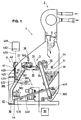
- the tobacco industry product manufacturing machine 1 Figure 1 is similar to that described in the aforementioned application and includes in particular a tobacco supply part 2, preferably a lock tangential, part of distribution or distributor 3, part of production of the tobacco rod 4 and a training and control part 5.
- the distributor 3 withdraws the tobacco from an intermediate stock 30, using the continuous strip with combs 31 to bring it onto the continuous treadmill of transfer 32.
- the tobacco flow is equalized by a first continuous band of equalization 33, while the tobacco flow is oriented on the transfer belt 32 by means of the deflector 34.
- the detection cell 35 controls the amount of tobacco on the transfer belt 32.
- a second strip continuous equalization 36 compact and equalizes the flow of tobacco near the end of the transfer belt 32, while a pin roller 37 untangles, mixes and expands the tobacco flow before it is projected and essentially descends by gravitation in the transfer pipe 38.
- the confection part of the flange 4 comprises a suction chamber 40, connected by a pipe, shown schematically at 400, to a suction unit 401.
- the air suction circuit begins with a suction opening arranged at near the lower portion of line 38, passes through the chamber separation 38A, the suction chimney 42 and the porous belt 41 disposed directly in the lower part of the suction chamber 40.
- Tobacco flow from the upper portion of pipeline 38 therefore separates in the separation chamber 38A into two portions, one first portion sucked into the suction chimney 42 and containing the elements intended to form the tobacco rod under the porous belt 41, while the second portion, formed of heavier elements not intended for form the sausage, fall by gravity into a disposal tank or mat 39.
- the reference application also describes a movable valve 43, loaded, in position closed as shown in Figure 1, to allow passage to the ribs, ribs and stems of large section forming the second portion of flux mentioned above, to fall into the disposal bin or disposal mat 39.
- This valve 43 is actuated by a jack 430, or any other suitable actuator, between the closed position of Figure 1 and the open position of Figures 4 and 5.
- the request in reference indicates that this valve 43, in the open position, allows to recover the complete tobacco flow, coming from the upper portion of the pipe 38, in the event of a stop of the porous belt 41 or stop of aspiration.
- the tobacco flow is directed by gravitation to a recovery means 44, for example a transfer mat, to be brought back to stock 30.
- the means enabling the flow of tobacco from transfer mat 44 to stock 30, can be made another transfer mat 440, directed essentially transversely relative to the axis of the machine, bringing the tobacco onto yet another mat transfer 441 which is perpendicular to it and which distributes the tobacco in a lower portion 300 of the stock 30.
- the various transfer belts 44, 440 and 441 described here can for example be generally intended for recovery tobacco strands cut by the means of clipping of the rod (not shown in the figure) arranged under a portion downstream of the belt porous 41. Since these strands are cut, they are generally long less than uncut strands from the tobacco supply means 2 and are therefore preferably introduced into a lower portion 300 of the stock 30, this so that the tobacco flow is formed as described in more detail in the ask for reference.
- tobacco jams can come essentially in three places: first on the first transfer mat 32 or else in the line 38, directly above the separation chamber 38A or still in the chimney 42, under the porous belt 41.
- a machine capable of carry out automatic cleaning operations is provided with the elements following: first of all the equalization strip 36 arranged opposite the mat transfer 32 is mounted in a mobile manner and is provided with a jack or the like actuating means 360, capable of spreading the equalizing strip 36 from the mat transfer 32, as seen in Figure 4.
- the underside of the pipe 38 is provided with a movable wall 380, able to pivot around a axis 381, arranged perpendicularly and preferably directly below from the downstream end of the transfer belt 32, the movable wall 380 being able to close, as shown in Figure 1, or open, as shown in Figures 4 and 5, by the action of a jack or any other actuator 382.
- a detection cell 383 is also arranged in the pipeline. 38, above the separation chamber 38A. This detection cell 383 is able to detect a jam at this location. Indeed, the tobacco flow is generally discontinuous at this point, making detector 383 sometimes excited, sometimes de-excited. A check on the status of the detector covering a period determined without change of state of detector 383 indicates a jam of tobacco there or upstream.
- the chimney 42 is also provided with a detector 420, capable of detecting a jam under the porous belt 41 of the same way as the previous detector 383.
- the chimney 42 is also provided with a movable wall 421, able to pivot, as shown in the figures 4 and 5, around an axis 422, under the action of a jack 423 or other actuator.
- the axis 422 is disposed close to the porous belt 41, causing the movable wall 421 to open downward.
- the air suction unit 401 is furthermore provided with a shut-off valve, shown diagrammatically at 402.
- the suction unit 401 and / or the valve 402 can be designed to be able to reverse the air flow in the pipeline 400.
- the drive control means of the different carpets transfer, equalization bands as well as spike roller 37 are in besides able to control the drive of these various elements at speed reduced as we will see below.
- FIGS. 2A and 3A show sections perpendicular to a portion of the making-up portion of the sausage 4.
- the porous belt 41 of which only a portion center of the lower strand is shown here, runs longitudinally between two vertical walls limiting a lower portion of the suction chamber 40.
- a cleaning device is mounted above the porous belt 41, in the suction chamber 40, consisting of a cylinder or any other actuator 410 controlling the longitudinal movement of a bar 411 to which are connected to cam means 412, 413, shown schematically here by two examples of different embodiments and arranged near the ends of the lower strand of the porous strip 41.
- cams 412, 413 push the porous strip 41 downwards, causing the latter to emerge from the two vertical walls limiting the suction chamber 40, as seen in Figures 2B and 3B.
- Other forms of the device for cleaning the porous belt 41 are obviously possible, in particular each cam can be replaced by a small vertical cylinder whose moving part acts directly on the belt porous 41.
- the control unit 50 receives its information from the various detectors of jamming mentioned above, in particular the detector 35 on the transfer belt 32, detector 383 in line 38 and detector 420 in the suction chimney.
- the same control unit 50 is capable of order the various drives, from the continuous strip with combs 31, from the EQ band 33, transfer band 32, second band equalization 36, of the pin roller 37, these elements being able to be simultaneously or independently stopped or controlled at reduced speed, at variable speed or normal speed.
- the control unit 50 is furthermore able to control the cylinders or actuators 360 of the second strip equalization 36, 382 of the movable wall 380, 430 of the movable valve 43, 422 of the movable wall 421 as well as the valve 402 controlling the stopping or the change of direction of flow of the suction unit 401.
- the control unit 50 preferably comprises a microprocessor unit provided with a program for performing the various operations described above and lower.
- Figure 4 shows the cigarette making machine in position of cleaning of a jam occurring on the transfer belt 32.
- a jam at this location can be signaled either by the detector 35 which signals that the thickness of the tobacco layer on the transfer tape 32 has exceeded a limit value, either by one of the detectors 383 or 420 signaling the absence of the tobacco flow in the respective places controlled by each detector, the microprocessor program being able to correlate the information received from these various detectors.
- the manufacturing machine can be put back in works, manually or automatically.
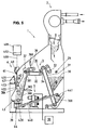
- Figure 5 shows the cigarette making machine in position of cleaning of a jam intervened in the pipe of transfer 38 or into the suction chimney 42.
- a jam in the line 38 can be reported either by the detector 383 which signals a heap of tobacco above the chamber separation 38A, either by the detector 420 signaling the absence of the tobacco flow in the chimney 42.
- a jam in the chimney 42 is signaled by the detector 420.
- the manufacturing machine can be put back in works, manually or automatically.
- the tobacco contained in the suction chimney 42 flows, when disposed of as directed, in the direction reverse flow of tobacco when the machine is running in production. This is possible by stopping the suction as well as by opening the movable wall 421, which restores atmospheric pressure at the top of the chimney 42 and allows the flow of tobacco in this place by gravity.
- the valve 402 and / or the suction unit 401 are designed to be able to reverse the air flow in line 400 and the chamber suction 40, to help unhook the tobacco strands from the belt porous 41 as well as the elimination of tobacco from the chimney 42 in position opened.
- the operation of closing valve 402 can be replaced by an inversion operation air flow, the reverse air flow can be maintained until it is indicated that the suction is restored or can be maintained for a period determined followed by a time when the air flow is completely interrupted, until the suction is normally restored.
Landscapes
- Manufacturing Of Cigar And Cigarette Tobacco (AREA)
Priority Applications (5)
| Application Number | Priority Date | Filing Date | Title |
|---|---|---|---|
| EP98810954A EP0988802A1 (de) | 1998-09-22 | 1998-09-22 | Ausstossverfahren für eine Herstellungsmaschine für Tabakprodukte sowie eine nach dem Verfahren arbeitende Maschine |
| PCT/CH1999/000448 WO2000016648A1 (en) | 1998-09-22 | 1999-09-21 | Method of unblocking a machine for manufacture of products of the tobacco industry and manufacturing machine operating according to said method |
| AU56148/99A AU5614899A (en) | 1998-09-22 | 1999-09-21 | Method of unblocking a machine for manufacture of products of the tobacco industry and manufacturing machine operating according to said method |
| PL99335537A PL335537A1 (en) | 1998-09-22 | 1999-09-22 | Method of cleaning a tobacco industry machine and tobacco industry machine operating in accordance with that method |
| HU9903222A HUP9903222A3 (en) | 1998-09-22 | 1999-09-22 | Produce for plugger remover of tobaccoproducts apparatus and the apparatus for producing of tobaccoproducts |
Applications Claiming Priority (1)
| Application Number | Priority Date | Filing Date | Title |
|---|---|---|---|
| EP98810954A EP0988802A1 (de) | 1998-09-22 | 1998-09-22 | Ausstossverfahren für eine Herstellungsmaschine für Tabakprodukte sowie eine nach dem Verfahren arbeitende Maschine |
Publications (1)
| Publication Number | Publication Date |
|---|---|
| EP0988802A1 true EP0988802A1 (de) | 2000-03-29 |
Family
ID=8236343
Family Applications (1)
| Application Number | Title | Priority Date | Filing Date |
|---|---|---|---|
| EP98810954A Withdrawn EP0988802A1 (de) | 1998-09-22 | 1998-09-22 | Ausstossverfahren für eine Herstellungsmaschine für Tabakprodukte sowie eine nach dem Verfahren arbeitende Maschine |
Country Status (5)
| Country | Link |
|---|---|
| EP (1) | EP0988802A1 (de) |
| AU (1) | AU5614899A (de) |
| HU (1) | HUP9903222A3 (de) |
| PL (1) | PL335537A1 (de) |
| WO (1) | WO2000016648A1 (de) |
Cited By (3)
| Publication number | Priority date | Publication date | Assignee | Title |
|---|---|---|---|---|
| WO2000040105A1 (fr) | 1998-12-30 | 2000-07-13 | Philip Morris Products S.A. | Procede de distribution des constituants de tabac, et distributeur d'une machine de fabrication de produits a fumer |
| EP1250855A1 (de) * | 2001-04-21 | 2002-10-23 | Hauni Maschinenbau AG | Verfahren und Vorrichtung zum Beseitigen einer Störung in einem Tabakkanal einer Zigarettenstrangmaschine |
| EP1704785A1 (de) * | 2005-03-24 | 2006-09-27 | G.D.S.p.A. | Verfaher und Vorrichtung zur Herstellung von Tabakprodukte |
Families Citing this family (3)
| Publication number | Priority date | Publication date | Assignee | Title |
|---|---|---|---|---|
| DE102004008116A1 (de) * | 2004-02-18 | 2005-09-15 | Hauni Primary Gmbh | Verfahren und Vorrichtung zum Zuführen von Schnitttabak in eine Verteilereinheit |
| EP1880416B1 (de) | 2005-05-10 | 2012-01-18 | Dow Corning Corporation | Verfahren zur minimierung von elektromigration bei einer elektronischen vorrichtung |
| ITUA20161310A1 (it) * | 2016-06-24 | 2017-12-24 | Gd Spa | Macchina e metodo per il confezionamento di sigarette. |
Citations (5)
| Publication number | Priority date | Publication date | Assignee | Title |
|---|---|---|---|---|
| GB1220372A (en) * | 1967-04-06 | 1971-01-27 | Seita | Improvements in or relating to apparatus for treating material in divided form |
| GB2088693A (en) | 1980-11-21 | 1982-06-16 | Sasib Spa | Pneumatically feeding cut tobacco braid in a cigarette making machine |
| EP0165080A1 (de) * | 1984-05-08 | 1985-12-18 | Japan Tobacco Inc. | Schnittabakzuführungsvorrichtung für eine Zigarettenherstellungsmaschine |
| GB2216768A (en) * | 1988-03-29 | 1989-10-18 | Koerber Ag | Method of and apparatus for eliminating irregularities from a stream of fibrous material |
| EP0917829A1 (de) | 1997-11-12 | 1999-05-26 | Fabriques De Tabac Reunies S.A. | Verfahren zur Abgabe eines Tabakstromes, Verteiler und Zigarettenherstellungsmaschine mit einem solchen Verteiler |
-
1998
- 1998-09-22 EP EP98810954A patent/EP0988802A1/de not_active Withdrawn
-
1999
- 1999-09-21 AU AU56148/99A patent/AU5614899A/en not_active Abandoned
- 1999-09-21 WO PCT/CH1999/000448 patent/WO2000016648A1/en not_active Ceased
- 1999-09-22 PL PL99335537A patent/PL335537A1/xx unknown
- 1999-09-22 HU HU9903222A patent/HUP9903222A3/hu unknown
Patent Citations (5)
| Publication number | Priority date | Publication date | Assignee | Title |
|---|---|---|---|---|
| GB1220372A (en) * | 1967-04-06 | 1971-01-27 | Seita | Improvements in or relating to apparatus for treating material in divided form |
| GB2088693A (en) | 1980-11-21 | 1982-06-16 | Sasib Spa | Pneumatically feeding cut tobacco braid in a cigarette making machine |
| EP0165080A1 (de) * | 1984-05-08 | 1985-12-18 | Japan Tobacco Inc. | Schnittabakzuführungsvorrichtung für eine Zigarettenherstellungsmaschine |
| GB2216768A (en) * | 1988-03-29 | 1989-10-18 | Koerber Ag | Method of and apparatus for eliminating irregularities from a stream of fibrous material |
| EP0917829A1 (de) | 1997-11-12 | 1999-05-26 | Fabriques De Tabac Reunies S.A. | Verfahren zur Abgabe eines Tabakstromes, Verteiler und Zigarettenherstellungsmaschine mit einem solchen Verteiler |
Cited By (3)
| Publication number | Priority date | Publication date | Assignee | Title |
|---|---|---|---|---|
| WO2000040105A1 (fr) | 1998-12-30 | 2000-07-13 | Philip Morris Products S.A. | Procede de distribution des constituants de tabac, et distributeur d'une machine de fabrication de produits a fumer |
| EP1250855A1 (de) * | 2001-04-21 | 2002-10-23 | Hauni Maschinenbau AG | Verfahren und Vorrichtung zum Beseitigen einer Störung in einem Tabakkanal einer Zigarettenstrangmaschine |
| EP1704785A1 (de) * | 2005-03-24 | 2006-09-27 | G.D.S.p.A. | Verfaher und Vorrichtung zur Herstellung von Tabakprodukte |
Also Published As
| Publication number | Publication date |
|---|---|
| HUP9903222A3 (en) | 2001-02-28 |
| HU9903222D0 (en) | 1999-11-29 |
| HUP9903222A2 (hu) | 2000-06-28 |
| WO2000016648A1 (en) | 2000-03-30 |
| AU5614899A (en) | 2000-04-10 |
| PL335537A1 (en) | 2000-03-27 |
Similar Documents
| Publication | Publication Date | Title |
|---|---|---|
| FR2597015A1 (fr) | Appareil de mise en place d'organes de fixation | |
| FR2549457A1 (fr) | Dispositif de recherche d'extremite de fil | |
| FR2527655A1 (fr) | Metier a tisser sans navette comprenant un moyen pour retirer des fils defectueux de trame, de la foule | |
| EP0988802A1 (de) | Ausstossverfahren für eine Herstellungsmaschine für Tabakprodukte sowie eine nach dem Verfahren arbeitende Maschine | |
| FR2493745A1 (fr) | Procede et dispositif pour mettre en place et regler une electrode d'usinage par electro-erosion | |
| FR2530927A1 (fr) | Appareil a enlever le cartilage de morceaux de viande | |
| FR2546190A1 (fr) | Procede et dispositif pour la mise en marche d'un groupe de filage a friction | |
| BE1001073A5 (fr) | Systeme pour remplir des conteneurs pour matieres en vrac a partir d'une tremie de stockage surelevee. | |
| FR2615701A1 (fr) | Procede pour deposer une formation continuellement extrudee sur un convoyeur a entrainement continu et dispositif pour la mise en oeuvre du procede | |
| CH410723A (fr) | Procédé de préparation d'une bobine au dévidage et appareil pour la mise en oeuvre du procédé | |
| FR3106586A1 (fr) | Dispositif permettant d'alimenter automatiquement sans discontinuer un Robot d'enfilage des chaussettes orientées dans le bon sens sur une formeuse par des bacs remplis de chaussettes en vrac | |
| FR2609239A1 (fr) | Procede et dispositif pour l'alimentation en tabac d'une machine a faire les cigarettes | |
| JP4382082B2 (ja) | タバコ加工産業のストランド切断装置及びストランド材料搬出装置 | |
| EP1583481B1 (de) | Verfahren und vorrichtung für den umgang mit schwergas | |
| FR2518510A1 (fr) | Procede et dispositif pour l'alignement et l'obtention, une a une, de canettes | |
| CH616829A5 (en) | automatic machine for making a clove hitch with a cord around an object and use of the machine | |
| EP1803557B1 (de) | Druckerpresse mit verbesserter Bahneinzugsvorrichtung und entsprechendes Bahneinzugsverfahren | |
| CH688595A5 (fr) | Appareil d'alimentation de film pour une machine automatique de développement de film. | |
| FR2659314A1 (fr) | Systeme de distribution de biere a la pression. | |
| EP0408519B1 (de) | Filtereinrichtung für eine Anlage zum kontinuierlichen Absaugen von textilen Abfällen von Maschinen zum Anfertigen von Textilien | |
| EP1803558A1 (de) | Druckeinheit mit Risikobegrenzung zur Beschädigung der Zylinder in Druck-Abstellung durch Papierbahnwickler und entsprechende Druckmaschine | |
| EP0570279B1 (de) | Automatische Elektroschock-Betäubungsanlage für Schlachtvieh | |
| FR3108594A1 (fr) | Dispositif de fourniture de film à une fardeleuse, avec au moins deux dévidoirs pourvus chacun d’un carter de recouvrement | |
| CH652761A5 (fr) | Dispositif de levee automatique sur machine a filer les gros numeros. | |
| EP1803560A1 (de) | Druckeinheit welche in Druck-Abstellung bei laufender Papierbahn den Wechsel einer Gummituchhülse ermöglicht und entsprechende Druckmaschine |
Legal Events
| Date | Code | Title | Description |
|---|---|---|---|
| PUAI | Public reference made under article 153(3) epc to a published international application that has entered the european phase |
Free format text: ORIGINAL CODE: 0009012 |
|
| AK | Designated contracting states |
Kind code of ref document: A1 Designated state(s): CH DE ES FR GB IT LI NL |
|
| AX | Request for extension of the european patent |
Free format text: AL;LT;LV;MK;RO;SI |
|
| AKX | Designation fees paid |
Free format text: CH DE ES FR GB IT LI NL |
|
| STAA | Information on the status of an ep patent application or granted ep patent |
Free format text: STATUS: THE APPLICATION IS DEEMED TO BE WITHDRAWN |
|
| 17P | Request for examination filed |
Effective date: 20000624 |
|
| 18D | Application deemed to be withdrawn |
Effective date: 20020403 |