EP0988873A2 - Collier de tuyaux intumescent - Google Patents
Collier de tuyaux intumescent Download PDFInfo
- Publication number
- EP0988873A2 EP0988873A2 EP99307486A EP99307486A EP0988873A2 EP 0988873 A2 EP0988873 A2 EP 0988873A2 EP 99307486 A EP99307486 A EP 99307486A EP 99307486 A EP99307486 A EP 99307486A EP 0988873 A2 EP0988873 A2 EP 0988873A2
- Authority
- EP
- European Patent Office
- Prior art keywords
- intumescent
- pipe collar
- pipe
- collar according
- intumescent material
- Prior art date
- Legal status (The legal status is an assumption and is not a legal conclusion. Google has not performed a legal analysis and makes no representation as to the accuracy of the status listed.)
- Withdrawn
Links
- 239000000463 material Substances 0.000 claims abstract description 66
- 239000004744 fabric Substances 0.000 claims abstract description 42
- 238000005192 partition Methods 0.000 claims abstract description 13
- 238000009434 installation Methods 0.000 claims description 3
- 238000001125 extrusion Methods 0.000 claims description 2
- 239000004033 plastic Substances 0.000 abstract description 6
- 229920003023 plastic Polymers 0.000 abstract description 6
- 239000000155 melt Substances 0.000 abstract description 5
- 230000004048 modification Effects 0.000 description 6
- 238000012986 modification Methods 0.000 description 6
- 239000002184 metal Substances 0.000 description 5
- 230000004888 barrier function Effects 0.000 description 4
- 238000009940 knitting Methods 0.000 description 3
- OKTJSMMVPCPJKN-UHFFFAOYSA-N Carbon Chemical compound [C] OKTJSMMVPCPJKN-UHFFFAOYSA-N 0.000 description 1
- 230000003628 erosive effect Effects 0.000 description 1
- 239000000835 fiber Substances 0.000 description 1
- 229910002804 graphite Inorganic materials 0.000 description 1
- 239000010439 graphite Substances 0.000 description 1
- 238000004519 manufacturing process Methods 0.000 description 1
- 238000002844 melting Methods 0.000 description 1
- 230000008018 melting Effects 0.000 description 1
- 238000000034 method Methods 0.000 description 1
- 239000000203 mixture Substances 0.000 description 1
- 230000000717 retained effect Effects 0.000 description 1
- 239000000779 smoke Substances 0.000 description 1
- XLYOFNOQVPJJNP-UHFFFAOYSA-N water Substances O XLYOFNOQVPJJNP-UHFFFAOYSA-N 0.000 description 1
Images

Classifications
-
- F—MECHANICAL ENGINEERING; LIGHTING; HEATING; WEAPONS; BLASTING
- F16—ENGINEERING ELEMENTS AND UNITS; GENERAL MEASURES FOR PRODUCING AND MAINTAINING EFFECTIVE FUNCTIONING OF MACHINES OR INSTALLATIONS; THERMAL INSULATION IN GENERAL
- F16L—PIPES; JOINTS OR FITTINGS FOR PIPES; SUPPORTS FOR PIPES, CABLES OR PROTECTIVE TUBING; MEANS FOR THERMAL INSULATION IN GENERAL
- F16L5/00—Devices for use where pipes, cables or protective tubing pass through walls or partitions
- F16L5/02—Sealing
- F16L5/04—Sealing to form a firebreak device
-
- A—HUMAN NECESSITIES
- A62—LIFE-SAVING; FIRE-FIGHTING
- A62C—FIRE-FIGHTING
- A62C2/00—Fire prevention or containment
- A62C2/06—Physical fire-barriers
- A62C2/065—Physical fire-barriers having as the main closure device materials, whose characteristics undergo an irreversible change under high temperatures, e.g. intumescent
Definitions
- This invention relates to an intumescent pipe collar of the kind protecting a hole in a partition through which a pipe means extends, and comprising a support means adapted to extend around the pipe means in or adjacent to the partition, and intumescent material adapted to be provided between the pipe means and the support means.
- the pipe means is a pipe of plastics material then in the event of a fire it melts at a relatively low temperature, leaving a passage in the partition through which the fire or smoke can spread.
- An intumescent pipe collar ensures that the passage is blocked in the event of a fire, by the intumescent material which expands at a relatively low temperature. As the support collar prevents the intumescent material expanding outwards, it expands inwardly across the passage left by melting of the pipe, and axially along the pipe. The intumescent material therefore provides a physical barrier in the hole through which the pipe passed.
- the pipe means may be a bundle of pipes, or cables, or indeed any elongate member likely to melt or be destroyed in a fire.
- the intumescent material is held in a stretchable element extending circumferentially and covering at least the radially inner surface and the axial end surfaces of the intumescent material, the stretchable element being arranged in use to stretch more in a radial direction than an axial direction.
- the stretchable element therefore guides the expansion of the intumescent material in a radially inward direction, that is, across the passage, rather than an axial direction. There is therefore less intumescent material expanding along the pipe, so that less is wasted, and because the intumescent material is guided to the right place when it expands, less intumescent material is needed in the first place.
- the stretchable element also acts to reinforce the barrier created by the expanded intumescent material.
- the intumescent material comprises an elongate hollow member.
- the intumescent elongate hollow member is preferably cylindrical, to fit round a circular pipe means. It may however be of hollow rectangular form, or any appropriate shape needed to fit the pipe means.
- the stretchable element is made from fabric as this assists the intermingling of the stretchable element and the intumescent material upon expansion of the intumescent material.
- the fabric element is preferably knitted from at least one yarn.
- a knitted fabric can easily be arranged to provide the preferential stretching required, either by the yarn used or the type of stitch.
- Preferably a different stitch is used on the radial surface of the fabric element from the axial surfaces of the fabric elements.
- Advantageously stocking stitch is used on the axial surfaces and ribbing stitch is used on the radial surface.
- the intumescent material preferably contains an axially-extending gap. This enables the intumescent material to open to allow the pipe collar to be fitted round an existing pipe means.
- the material is preferably formed by extrusion and advantageously comprises a flexible strip which is adapted to be cut to length for installation of the pipe collar, enabling the same strip to be used for different sizes of pipe. It would however, be possible for the intumescent member to be made as a closed member, which could be used where the pipe collar is assembled on the partition before the pipe means is fitted.
- the stretchable element is preferably tubular and encloses the radially outer surface as well as the radially inner surface and the axial end surfaces of the intumescent material in use.
- the stretchable element may comprise an elongate sleeve into which a strip of intumescent material is inserted. The ends of the sleeve may be overlapped or joined radially.
- the stretchable element may be a tube whose ends are joined circumferentially round the intumescent member.
- the stretchable element is preferably flame-resistant. Where it is a fabric element, it stretches as the intumescent material expands and the gaps between adjacent fibres in the fabric element enlarge. The intumescent material then expands through these gaps, so that it becomes intermingled with the fabric and protects it from the fire, while the fabric element reinforces the intumescent material.
- the fabric element may contain fibres or a yarn which is less elastic than the rest of the fibres or yarns, and which is destroyed at a temperature below that at which the intumescent material expands. These fibres help to maintain the shape of the fabric element, preventing it stretching during assembly of the intumescent material into the fabric element, and while the pipe collar is being assembled round the pipe. However these fibres are destroyed in the event of a fire, allowing the fabric element to stretch as required.
- the support means is preferably substantially rigid in use, and preferably comprises a substantially rigid support collar in which the intumescent material is accommodated.
- it may be provided by the stretchable element, for example appropriate fibres or yarns may provide the necessary strength to support the intumescent material, particularly as it expands.
- support means may be provided by the partition.
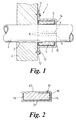
- Figure 1 shows an intumescent pipe collar 1 supported round a cylindrical plastics pipe 2 which extends through a hole 3 in a partition 4, in this case a wall.
- the intumescent pipe collar 1 acts in the event of a fire, when the plastics pipe 2 melts, to block the passage in the hole 3 left when the pipe 2 melts.
- the intumescent pipe collar 1 comprises a rigid annular metal support collar 5 in which is retained a hollow cylindrical member 6 of intumescent material contained in a stretchable fabric element 7.
- the intumescent member is arranged between the collar 5 and the pipe 2, and will expand in the event of a fire, at a predetermined relatively low temperature.
- the stretchable fabric element 7 is arranged to stretch more in a radial direction than an axial direction, to guide the expanding intumescent material to expand radially rather than axially.
- the metal collar 5 is made of a one piece strip, bent round so that its ends 8,9 are adjacent but separated by a split extending axially to allow the collar 5 to open to fit round the pipe 2.
- the ends 8,9 have inturned flanges 10 for strength, and an over centre catch mechanism (not shown) is attached to the outside of the collar 5 to lock the collar 5 closed, and keep it rigid.
- the collar 5 has out-turned flanges 12 by which it is attached to the wall 4 by suitable fixing means, such as screws 13.
- the collar 5 has inturned flanges 15 which retain the intumescent material.
- the intumescent member 6 is shown in more detail in Figures 2 and 3. It comprises an elongate strip 16 of intumescent material of rectangular cross-section.
- the intumescent material may be of any suitable type, for example a mixture of graphite and plastics materials which can be extruded into a continuous length of strip 16.
- the strip 16 is cut to the appropriate length, and is bent round into a cylinder, so that its free ends 16a engage the inturned flanges 10 on the ends of the collar 5.
- the strip 16 fits into the collar 5, and opens with it for fitting round the pipe 2.
- the intumescent strip 16 is held in the stretchable fabric element 7, which surrounds it.
- the fabric element 7 is a tubular sleeve 17, and the intumescent strip 16 is inserted into it, the ends of the sleeve 17 being closed or folded over the ends of the strip 16.
- the fabric element 7 is knitted from flame-resistant yarn or yarns in such a way that when in a position of use it stretches more in a radially inwards direction than axially.
- Figure 2 shows diagrammatically how the difference in stretchability is provided by a difference in the type of stitch used in the knitting.
- the stitch used on the axial end faces 18, 19 and the radially outer surface 20 is not very stretchy (for example, stocking stitch) whereas the stitch used on the radially inner surface 21 is much more stretchy, being for example a ribbing stitch. It is of course possible to obtain the differential stretching of the fabric element 7 in other ways, for example by the use of different yarns or different tension in the knitting process.
- the intumescent pipe collar 1 is assembled by enclosing a strip 16 of appropriate length in a sleeve 17 of appropriate length, and then inserting it in the metal collar 5 from the end 11.
- the strip 16 in the sleeve 17 is held in place by the flanges 15 and the end flanges 10.
- the collar 1 can then be opened and fitted round the pipe 2, and the catch mechanism closed.
- the collar is then fastened to the wall 4 by the fixing screws 13 and the flanges 12. In this position the intumescent material, encased in the fabric element 7, is between the collar 5 and the pipe 2.
- the plastics pipe 2 melts at a relatively low temperature.
- the intumescent strip 16 then expands, and is guided by the fabric element 7 to expand more radially than axially, in order to fill the gap left by the melted pipe 2. This is shown in Figure 5.
- the fabric element 7 is flame-resistant, it will not be destroyed immediately, and when it expands the gaps in the knitting enlarge, allowing intumescent material through.
- the intumescent material and the fabric element 7 become intermingled.
- the intumescent material protects the fabric yarn from the fire, while the fabric reinforces and strengthens the intumescent material.
- the use of the fabric element 7 to guide the expanding intumescent material reduces the amount of intumescent material that is wasted in axial expansion, and thus the amount that is needed in the first place.
- the fabric element 7 contains a yarn which is less elastic than the other yarn or yarns, but which is destroyed at a temperature below that at which the intumescent material expands.
- the less elastic yarn is arranged to help maintain the shape of the fabric element 7 during assembly of the collar 1 and its installation. However, this yarn is destroyed in a fire, allowing the fabric element 7 to stretch as required.
- the metal collar 5 is omitted, and the fabric element 7 instead acts as the support collar.
- the fabric element 7 then has a portion, located on the radially outer surface of the intumescent member 6, formed from a fibre or yarn providing the appropriate tensile strength to support the intumescent material, particularly when it expands.
- the partition 4 acts as a support.
- the collar is placed around the pipe 3 in the partition 4 and the partition 4 supports the intumescent material, especially when it expands.
- the metal collar 5 is formed as a closed circle, for use where the pipe collar 1 is fitted first and then the pipe 2 is inserted through it.
- the intumescent member is still made from a length of elongate strip 16 encased in a sleeve 17, with the ends of the sleeve 17 being overlapped as shown. Alternatively, the ends of the sleeve 17 could be joined together, to form a torus.
- the intumescent member 6 may also be made as an annulus.
- the fabric element 7 then comprises a sleeve of greater diameter, which is folded round the annulus and has a join or overlap extending circumferentially.
- the collar 1 shown is of circular cross-section, but it is possible for it to have a rectangular or polygonal cross-section.
- the intumescent strip 16 being flexible, can fit these cross-sections as well.
- the intumescent strip 16 may be extruded as one hollow member, as shown herein. Alternatively, it may comprise several such members or alternatively many pieces of intumescent material. These could, for example, be offcuts from another manufacturing process.
- the intumescent material may take up the shape of the sleeve.
- the expansion of the intumescent material may be guided by one or a plurality of stretchable elements 17. Although these stretchable elements are shown as made from a fabric they may of course comprise any suitable stretchable material.
Landscapes
- Engineering & Computer Science (AREA)
- General Engineering & Computer Science (AREA)
- Mechanical Engineering (AREA)
- Health & Medical Sciences (AREA)
- Public Health (AREA)
- Business, Economics & Management (AREA)
- Emergency Management (AREA)
- Protection Of Pipes Against Damage, Friction, And Corrosion (AREA)
- Building Environments (AREA)
- Connection Of Plates (AREA)
- Rigid Pipes And Flexible Pipes (AREA)
Applications Claiming Priority (2)
| Application Number | Priority Date | Filing Date | Title |
|---|---|---|---|
| GB9820618 | 1998-09-23 | ||
| GBGB9820618.8A GB9820618D0 (en) | 1998-09-23 | 1998-09-23 | Intumescent pipe collar |
Publications (2)
| Publication Number | Publication Date |
|---|---|
| EP0988873A2 true EP0988873A2 (fr) | 2000-03-29 |
| EP0988873A3 EP0988873A3 (fr) | 2000-07-12 |
Family
ID=10839262
Family Applications (1)
| Application Number | Title | Priority Date | Filing Date |
|---|---|---|---|
| EP99307486A Withdrawn EP0988873A3 (fr) | 1998-09-23 | 1999-09-22 | Collier de tuyaux intumescent |
Country Status (4)
| Country | Link |
|---|---|
| EP (1) | EP0988873A3 (fr) |
| AU (1) | AU4883699A (fr) |
| GB (2) | GB9820618D0 (fr) |
| NO (1) | NO994609L (fr) |
Cited By (15)
| Publication number | Priority date | Publication date | Assignee | Title |
|---|---|---|---|---|
| EP1180629A2 (fr) | 2000-08-14 | 2002-02-20 | HILTI Aktiengesellschaft | Manchette de protection contre le feu |
| WO2004015319A1 (fr) * | 2002-08-09 | 2004-02-19 | Promat Australia Pty Ltd | Amortisseur annulaire pour gaines de contionnement d'air |
| AT411617B (de) * | 2000-10-02 | 2004-03-25 | Kamleithner Maly Uta Ing Mag | Brandschutz-manschette |
| AT509470A4 (de) * | 2010-05-21 | 2011-09-15 | Kamleithner Maly Uta Ing Mag | Schnelleinbau-brandschutzmodul |
| EP1630318B1 (fr) * | 2004-08-23 | 2012-01-11 | Dallmer GmbH & Co. KG | Bouche d'évacuation d'eau pour toiture |
| EP3047877A1 (fr) * | 2015-01-26 | 2016-07-27 | M.D.S. Meyer GmbH | Manchette pare-feu |
| EP3299688A1 (fr) * | 2016-09-21 | 2018-03-28 | HILTI Aktiengesellschaft | Composant ignifuge et procédé de fabrication d'un passage de conduite ignifuge |
| CN108195121A (zh) * | 2018-03-02 | 2018-06-22 | 中山市新顺翔电器制造有限公司 | 一种冰箱压缩机的底盘 |
| WO2021080484A1 (fr) * | 2019-10-24 | 2021-04-29 | Roxtec Ab | Joint coupe-feu et procédé de montage d'un joint coupe-feu |
| US11578822B2 (en) | 2013-12-09 | 2023-02-14 | Hilti Aktiengesellschaft | Device for passing pipes or cables through an opening in a building |
| US11628321B2 (en) | 2015-04-27 | 2023-04-18 | Hilti Aktiengesellschaft | Firestop collar |
| US11655919B2 (en) | 2015-04-27 | 2023-05-23 | Hilti Aktiengesellschaft | Fire protection sleeve |
| WO2024114938A1 (fr) * | 2022-12-02 | 2024-06-06 | Viega Technology Gmbh & Co. Kg | Élément de retenue comprenant un matériau intumescent |
| US12104737B2 (en) | 2016-10-05 | 2024-10-01 | Hilti Aktiengesellschaft | Line feed-through for feeding a line through a building component |
| US12467559B2 (en) | 2015-07-28 | 2025-11-11 | Hilti Aktiengesellschaft | Air, acoustic and/or fire sealing sleeve insert and air, acoustic and/or fire sealing device |
Families Citing this family (1)
| Publication number | Priority date | Publication date | Assignee | Title |
|---|---|---|---|---|
| DE102007000040A1 (de) | 2007-01-26 | 2008-09-04 | Hilti Ag | Vorrichtung zur Abschottung eines Leitungsstrangs |
Citations (1)
| Publication number | Priority date | Publication date | Assignee | Title |
|---|---|---|---|---|
| WO1997004838A1 (fr) | 1995-08-02 | 1997-02-13 | J.W. Bollom & Co. Ltd. | Collier pare-feu intumescent pour canalisations |
Family Cites Families (6)
| Publication number | Priority date | Publication date | Assignee | Title |
|---|---|---|---|---|
| US4559745A (en) * | 1983-12-22 | 1985-12-24 | Fire Research Pty. Limited | Devices for the fire stopping of plastics pipes |
| AU579880B2 (en) * | 1985-08-06 | 1988-12-15 | Fire Research Pty. Limited | Devices for the fire stopping of plastics pipes |
| US5058341A (en) * | 1989-08-31 | 1991-10-22 | Msp Products, Inc. | Method for constructing fire-stop collar assembly and apparatus thereof |
| DE4017656A1 (de) * | 1990-06-01 | 1991-12-05 | Minnesota Mining & Mfg | Vorrichtung zur abschottung eines durch eine wand hindurchgefuehrten kunststoffrohrs im brandfall |
| GB9319137D0 (en) * | 1993-09-15 | 1993-11-03 | Dufaylite Dev Ltd | Fire seal |
| JPH1089545A (ja) * | 1996-09-18 | 1998-04-10 | Toosetsu Kk | 防火区画貫通部材 |
-
1998
- 1998-09-23 GB GBGB9820618.8A patent/GB9820618D0/en not_active Ceased
-
1999
- 1999-09-21 AU AU48836/99A patent/AU4883699A/en not_active Abandoned
- 1999-09-22 NO NO994609A patent/NO994609L/no not_active Application Discontinuation
- 1999-09-22 GB GB9922287A patent/GB2341797B/en not_active Expired - Fee Related
- 1999-09-22 EP EP99307486A patent/EP0988873A3/fr not_active Withdrawn
Patent Citations (1)
| Publication number | Priority date | Publication date | Assignee | Title |
|---|---|---|---|---|
| WO1997004838A1 (fr) | 1995-08-02 | 1997-02-13 | J.W. Bollom & Co. Ltd. | Collier pare-feu intumescent pour canalisations |
Cited By (25)
| Publication number | Priority date | Publication date | Assignee | Title |
|---|---|---|---|---|
| EP1180629A3 (fr) * | 2000-08-14 | 2002-06-12 | HILTI Aktiengesellschaft | Manchette de protection contre le feu |
| US6477813B2 (en) * | 2000-08-14 | 2002-11-12 | Hilti Aktiengesellschaft | Fire protection sleeve |
| EP1180629A2 (fr) | 2000-08-14 | 2002-02-20 | HILTI Aktiengesellschaft | Manchette de protection contre le feu |
| AT411617B (de) * | 2000-10-02 | 2004-03-25 | Kamleithner Maly Uta Ing Mag | Brandschutz-manschette |
| WO2004015319A1 (fr) * | 2002-08-09 | 2004-02-19 | Promat Australia Pty Ltd | Amortisseur annulaire pour gaines de contionnement d'air |
| EP1630318B1 (fr) * | 2004-08-23 | 2012-01-11 | Dallmer GmbH & Co. KG | Bouche d'évacuation d'eau pour toiture |
| DE102011102727B4 (de) | 2010-05-21 | 2024-11-07 | Uta Kamleithner | Schnelleinbau-Brandschutzmodul |
| AT509470A4 (de) * | 2010-05-21 | 2011-09-15 | Kamleithner Maly Uta Ing Mag | Schnelleinbau-brandschutzmodul |
| DE102011102727A1 (de) | 2010-05-21 | 2012-03-29 | Uta Kamleithner-Maly | Schnelleinbau-Brandschutzmodul |
| AT509470B1 (de) * | 2010-05-21 | 2011-09-15 | Kamleithner Maly Uta Ing Mag | Schnelleinbau-brandschutzmodul |
| US11578822B2 (en) | 2013-12-09 | 2023-02-14 | Hilti Aktiengesellschaft | Device for passing pipes or cables through an opening in a building |
| US12253200B2 (en) | 2013-12-09 | 2025-03-18 | Hilti Aktiengesellschaft | Device for passing pipes or cables through an opening in a building |
| US11585466B2 (en) | 2013-12-09 | 2023-02-21 | Hilti Aktiengesellschaft | Device for passing pipes or cables through an opening in a building |
| US11913585B2 (en) | 2013-12-09 | 2024-02-27 | Hilti Aktiengesellschaft | Device for passing pipes or cables through an opening in a building |
| EP3047877A1 (fr) * | 2015-01-26 | 2016-07-27 | M.D.S. Meyer GmbH | Manchette pare-feu |
| US11628321B2 (en) | 2015-04-27 | 2023-04-18 | Hilti Aktiengesellschaft | Firestop collar |
| US12123534B2 (en) | 2015-04-27 | 2024-10-22 | Hilti Aktiengesellschaft | Fire protection sleeve |
| US11655919B2 (en) | 2015-04-27 | 2023-05-23 | Hilti Aktiengesellschaft | Fire protection sleeve |
| US12083366B2 (en) | 2015-04-27 | 2024-09-10 | Hilti Aktiengesellschaft | Firestop collar |
| US12467559B2 (en) | 2015-07-28 | 2025-11-11 | Hilti Aktiengesellschaft | Air, acoustic and/or fire sealing sleeve insert and air, acoustic and/or fire sealing device |
| EP3299688A1 (fr) * | 2016-09-21 | 2018-03-28 | HILTI Aktiengesellschaft | Composant ignifuge et procédé de fabrication d'un passage de conduite ignifuge |
| US12104737B2 (en) | 2016-10-05 | 2024-10-01 | Hilti Aktiengesellschaft | Line feed-through for feeding a line through a building component |
| CN108195121A (zh) * | 2018-03-02 | 2018-06-22 | 中山市新顺翔电器制造有限公司 | 一种冰箱压缩机的底盘 |
| WO2021080484A1 (fr) * | 2019-10-24 | 2021-04-29 | Roxtec Ab | Joint coupe-feu et procédé de montage d'un joint coupe-feu |
| WO2024114938A1 (fr) * | 2022-12-02 | 2024-06-06 | Viega Technology Gmbh & Co. Kg | Élément de retenue comprenant un matériau intumescent |
Also Published As
| Publication number | Publication date |
|---|---|
| GB2341797A (en) | 2000-03-29 |
| EP0988873A3 (fr) | 2000-07-12 |
| GB2341797B (en) | 2002-02-27 |
| NO994609L (no) | 2000-03-24 |
| GB9922287D0 (en) | 1999-11-17 |
| GB9820618D0 (en) | 1998-11-18 |
| AU4883699A (en) | 2000-03-30 |
| NO994609D0 (no) | 1999-09-22 |
Similar Documents
| Publication | Publication Date | Title |
|---|---|---|
| EP0988873A2 (fr) | Collier de tuyaux intumescent | |
| US5970670A (en) | Intumescent fire arrester collar for pipelines | |
| US5796045A (en) | Braided sheath sleeve for threading over at least one elongate element to be protected, and a method of manufacturing such a sleeve | |
| EP3025085B1 (fr) | Manchon textile protecteur enveloppant renforcé, et procédé de construction associé | |
| JP7066678B2 (ja) | 耐衝撃性があり収縮可能な編まれた管状スリーブおよびその構築方法 | |
| CN111065771B (zh) | 热熔粘合纱线编织纺织套筒及其制造方法 | |
| EP3478881B1 (fr) | Manchon textile rétractable et circonférentiellement continu et son procédé de construction | |
| CA2283238A1 (fr) | Articles tubulaires presentant des pinces de fixation exterieures | |
| EP3658706B1 (fr) | Manchon textile tressé avec fils bloqués et son procédé de construction | |
| EP3230506B1 (fr) | Gaîne protective tubulaire avec des lisières non enroulantes, procédé pour son obtention et méthode d'installation | |
| US10711378B2 (en) | Knit textile sleeve with self-sustaining expanded and contracted states and method of construction thereof | |
| MXPA97002399A (es) | Collarin protector contra el fuego, intumescente, para tuberias | |
| JP2017133576A (ja) | 織物管の接続方法 |
Legal Events
| Date | Code | Title | Description |
|---|---|---|---|
| PUAI | Public reference made under article 153(3) epc to a published international application that has entered the european phase |
Free format text: ORIGINAL CODE: 0009012 |
|
| AK | Designated contracting states |
Kind code of ref document: A2 Designated state(s): DE ES FR IT SE |
|
| AX | Request for extension of the european patent |
Free format text: AL;LT;LV;MK;RO;SI |
|
| PUAL | Search report despatched |
Free format text: ORIGINAL CODE: 0009013 |
|
| AK | Designated contracting states |
Kind code of ref document: A3 Designated state(s): AT BE CH CY DE DK ES FI FR GB GR IE IT LI LU MC NL PT SE |
|
| AX | Request for extension of the european patent |
Free format text: AL;LT;LV;MK;RO;SI |
|
| 17P | Request for examination filed |
Effective date: 20010108 |
|
| AKX | Designation fees paid |
Free format text: DE ES FR IT SE |
|
| STAA | Information on the status of an ep patent application or granted ep patent |
Free format text: STATUS: THE APPLICATION HAS BEEN WITHDRAWN |
|
| 18W | Application withdrawn |
Withdrawal date: 20020826 |