EP0988883B1 - Verfahren zur Behandlung von Gasen mittels Druckwechseladsorption mit variabler Produktion - Google Patents
Verfahren zur Behandlung von Gasen mittels Druckwechseladsorption mit variabler Produktion Download PDFInfo
- Publication number
- EP0988883B1 EP0988883B1 EP99402263A EP99402263A EP0988883B1 EP 0988883 B1 EP0988883 B1 EP 0988883B1 EP 99402263 A EP99402263 A EP 99402263A EP 99402263 A EP99402263 A EP 99402263A EP 0988883 B1 EP0988883 B1 EP 0988883B1
- Authority
- EP
- European Patent Office
- Prior art keywords
- cycle
- production
- pressure
- during
- adsorber
- Prior art date
- Legal status (The legal status is an assumption and is not a legal conclusion. Google has not performed a legal analysis and makes no representation as to the accuracy of the status listed.)
- Expired - Lifetime
Links
- 238000004519 manufacturing process Methods 0.000 title claims description 55
- 238000000034 method Methods 0.000 title claims description 24
- 238000001179 sorption measurement Methods 0.000 title claims description 12
- 230000008569 process Effects 0.000 title description 8
- QVGXLLKOCUKJST-UHFFFAOYSA-N atomic oxygen Chemical compound [O] QVGXLLKOCUKJST-UHFFFAOYSA-N 0.000 claims description 23
- 239000001301 oxygen Substances 0.000 claims description 23
- 229910052760 oxygen Inorganic materials 0.000 claims description 23
- 230000009467 reduction Effects 0.000 claims description 10
- 239000007789 gas Substances 0.000 claims description 9
- 238000011067 equilibration Methods 0.000 claims description 5
- 239000000203 mixture Substances 0.000 claims description 5
- 230000006837 decompression Effects 0.000 claims description 4
- 230000008929 regeneration Effects 0.000 claims description 4
- 238000011069 regeneration method Methods 0.000 claims description 4
- 150000001875 compounds Chemical class 0.000 claims description 2
- 238000009434 installation Methods 0.000 description 13
- 238000010926 purge Methods 0.000 description 10
- 238000010828 elution Methods 0.000 description 6
- 230000033228 biological regulation Effects 0.000 description 5
- 235000021183 entrée Nutrition 0.000 description 5
- 238000012937 correction Methods 0.000 description 4
- 230000007257 malfunction Effects 0.000 description 4
- 238000012986 modification Methods 0.000 description 4
- 230000004048 modification Effects 0.000 description 4
- 239000003463 adsorbent Substances 0.000 description 3
- 230000008859 change Effects 0.000 description 3
- 230000007423 decrease Effects 0.000 description 3
- IJGRMHOSHXDMSA-UHFFFAOYSA-N Atomic nitrogen Chemical compound N#N IJGRMHOSHXDMSA-UHFFFAOYSA-N 0.000 description 2
- 230000008901 benefit Effects 0.000 description 2
- 238000004891 communication Methods 0.000 description 2
- 230000000694 effects Effects 0.000 description 2
- 238000003860 storage Methods 0.000 description 2
- WHXSMMKQMYFTQS-UHFFFAOYSA-N Lithium Chemical group [Li] WHXSMMKQMYFTQS-UHFFFAOYSA-N 0.000 description 1
- 229910021536 Zeolite Inorganic materials 0.000 description 1
- 230000006978 adaptation Effects 0.000 description 1
- 230000000903 blocking effect Effects 0.000 description 1
- 230000015556 catabolic process Effects 0.000 description 1
- 230000007547 defect Effects 0.000 description 1
- 238000006731 degradation reaction Methods 0.000 description 1
- 230000001934 delay Effects 0.000 description 1
- HNPSIPDUKPIQMN-UHFFFAOYSA-N dioxosilane;oxo(oxoalumanyloxy)alumane Chemical compound O=[Si]=O.O=[Al]O[Al]=O HNPSIPDUKPIQMN-UHFFFAOYSA-N 0.000 description 1
- 230000004064 dysfunction Effects 0.000 description 1
- 229940082150 encore Drugs 0.000 description 1
- 238000005265 energy consumption Methods 0.000 description 1
- 230000001667 episodic effect Effects 0.000 description 1
- 238000000605 extraction Methods 0.000 description 1
- 230000004907 flux Effects 0.000 description 1
- 239000008246 gaseous mixture Substances 0.000 description 1
- 238000002955 isolation Methods 0.000 description 1
- 229910052744 lithium Chemical group 0.000 description 1
- 230000033001 locomotion Effects 0.000 description 1
- 238000012423 maintenance Methods 0.000 description 1
- 238000005259 measurement Methods 0.000 description 1
- 239000002808 molecular sieve Substances 0.000 description 1
- 229910052757 nitrogen Inorganic materials 0.000 description 1
- 230000000737 periodic effect Effects 0.000 description 1
- 230000010363 phase shift Effects 0.000 description 1
- 238000011084 recovery Methods 0.000 description 1
- 238000004064 recycling Methods 0.000 description 1
- 238000007789 sealing Methods 0.000 description 1
- URGAHOPLAPQHLN-UHFFFAOYSA-N sodium aluminosilicate Chemical group [Na+].[Al+3].[O-][Si]([O-])=O.[O-][Si]([O-])=O URGAHOPLAPQHLN-UHFFFAOYSA-N 0.000 description 1
- 238000012360 testing method Methods 0.000 description 1
- 238000011144 upstream manufacturing Methods 0.000 description 1
- 238000013022 venting Methods 0.000 description 1
- 239000002912 waste gas Substances 0.000 description 1
- 239000002699 waste material Substances 0.000 description 1
- 239000010457 zeolite Substances 0.000 description 1
Images


Classifications
-
- B—PERFORMING OPERATIONS; TRANSPORTING
- B01—PHYSICAL OR CHEMICAL PROCESSES OR APPARATUS IN GENERAL
- B01D—SEPARATION
- B01D53/00—Separation of gases or vapours; Recovering vapours of volatile solvents from gases; Chemical or biological purification of waste gases, e.g. engine exhaust gases, smoke, fumes, flue gases, aerosols
- B01D53/02—Separation of gases or vapours; Recovering vapours of volatile solvents from gases; Chemical or biological purification of waste gases, e.g. engine exhaust gases, smoke, fumes, flue gases, aerosols by adsorption, e.g. preparative gas chromatography
- B01D53/04—Separation of gases or vapours; Recovering vapours of volatile solvents from gases; Chemical or biological purification of waste gases, e.g. engine exhaust gases, smoke, fumes, flue gases, aerosols by adsorption, e.g. preparative gas chromatography with stationary adsorbents
- B01D53/047—Pressure swing adsorption
- B01D53/053—Pressure swing adsorption with storage or buffer vessel
-
- B—PERFORMING OPERATIONS; TRANSPORTING
- B01—PHYSICAL OR CHEMICAL PROCESSES OR APPARATUS IN GENERAL
- B01D—SEPARATION
- B01D2256/00—Main component in the product gas stream after treatment
- B01D2256/12—Oxygen
-
- B—PERFORMING OPERATIONS; TRANSPORTING
- B01—PHYSICAL OR CHEMICAL PROCESSES OR APPARATUS IN GENERAL
- B01D—SEPARATION
- B01D2259/00—Type of treatment
- B01D2259/40—Further details for adsorption processes and devices
- B01D2259/40011—Methods relating to the process cycle in pressure or temperature swing adsorption
- B01D2259/40077—Direction of flow
- B01D2259/40079—Co-current
-
- B—PERFORMING OPERATIONS; TRANSPORTING
- B01—PHYSICAL OR CHEMICAL PROCESSES OR APPARATUS IN GENERAL
- B01D—SEPARATION
- B01D2259/00—Type of treatment
- B01D2259/40—Further details for adsorption processes and devices
- B01D2259/40011—Methods relating to the process cycle in pressure or temperature swing adsorption
- B01D2259/40077—Direction of flow
- B01D2259/40081—Counter-current
-
- B—PERFORMING OPERATIONS; TRANSPORTING
- B01—PHYSICAL OR CHEMICAL PROCESSES OR APPARATUS IN GENERAL
- B01D—SEPARATION
- B01D2259/00—Type of treatment
- B01D2259/40—Further details for adsorption processes and devices
- B01D2259/402—Further details for adsorption processes and devices using two beds
Definitions
- EP-A-0 819 463 which describes the arrangement of episodic dead times between the inter-adsorber equilibration step and the final pressurization / depressurization step.
- the present invention is particularly applicable to transatmospheric impure oxygen production cycles, typically having a purity of the order of 90 to 95%, from atmospheric air.
- This production gas will be called "oxygen" in the following.
- the pressures here are absolute pressures.
- the object of the invention is to provide a PSA method, typically with a transatmospheric mode, allowing an economical adaptation to a variable production flow rate, as well as an easy control of the tightness of the valves.
- the object of the invention is a process of the aforementioned type, characterized in that the dead time is added substantially to at least one extreme pressure PM and / or Pm of the cycle.
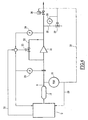
- the installation represented by way of example in FIG. 1 is particularly suitable for the production of oxygen, in particular so-called impure oxygen (called "oxygen” for the sake of simplicity), with a content preferably of between 90 and About 95% from atmospheric air.
- the installation essentially comprises two adsorbers 1A and 1B, a compressor or a fan 2, a vacuum pump 3 and a set of pipes and valves, as well as control and regulation means (not shown), adapted to implement the cycle described below.
- the compressor and the pump are volumetric machines of the "Roots" type, and rotate continuously at constant speed.
- the suction of the compressor 2 and the delivery of the vacuum pump 3 are in permanent communication with the surrounding atmosphere.
- the adsorbers 1A to 1B each contain at least one bed of an adsorbent adapted to selectively adsorb nitrogen from air, which in this example is a CaA type molecular sieve or a lithium exchanged zeolite.
- by-pass 15 and 16 provided with a respective valve 17, 18, are respectively stitched on the lines 4 and 7, just downstream of the compressor 2 and just upstream of the pump 3. These by-pass open into the surrounding atmosphere.
- the high pressure PM of the cycle is clearly greater than atmospheric pressure and chosen to be equal to 1.40 bar, whereas the low pressure Pm of the cycle is well below atmospheric pressure and is chosen to be 0, 4 bar.
- the cycle will be described below for an adsorber, namely adsorber 1A, and for the nominal flow rate of oxygen production.
- the other adsorber 1B follows an identical cycle but shifted in time by half a period T / 2.
- FIG 3 illustrates a modification of the cycle of Figure 2 for a reduced production rate.
- this modification consists solely in an extension of the duration T of the cycle by introducing two dead times, denoted TM1 and TM2, one (TM1) immediately following the last adsorption step (b2). ), and the other (TM2) immediately before the first repressurization step (a1).
- TM1 and TM2 two dead times, denoted TM1 and TM2, one (TM1) immediately following the last adsorption step (b2). ), and the other (TM2) immediately before the first repressurization step (a1).
- the adsorber is isolated, that is to say that all the valves connected to its inlet and outlet are closed, and the corresponding machine, namely the compressor 2 for TM1 and the pump 3 for TM2, is switched on empty via its bypass 15 or 16.
- the dead time TM1 is provided when the adsorber is at the high pressure PM, while the dead time TM2 is provided when the adsorber is at the low pressure Pm.
- the two dead times are concomitant, that is to say, simultaneous and of equal duration. While the adsorber 1A is in the dead time TM1, the adsorber 1B is in the dead time TM2 and vice versa.
- the duration ⁇ T (which may vary over time with the variations of the oxygen flow rate required) can be taken into account immediately, that is to say act on the cycle in progress or the following, or after a certain delay according to the measurement of the flow DR, to verify that it is not a simple fluctuation of the flow of oxygen consumed.
- the process may alternatively be modified as follows: the purity of the product oxygen is measured and, if a modification is observed, for example a degradation , excessive of this purity in the reduced step described above, the value of ⁇ T obtained by formula (2) is corrected in the direction which restores the nominal purity, that is to say, ⁇ T is reduced.
- This correction can easily be done automatically.
- the pressure of the adsorbers and the buffer capacity are continuously measured during the idle times. If this pressure varies, that is to say decreases for the dead time TM1 and / or increases for the dead time TM2, it follows that one of the corresponding valves leaks.
- the adsorber 1A is at low pressure Pm and its pressure rises during the timeout TM2, while the pressure of the adsorber 1B remains stable and that of the buffer capacity normally varies, it is deduced that the air valve 4A or vacuum 8A of the adsorber 1A leaks.
- the control of the variation of the pressure in the adsorbers can be carried out automatically, and an alarm can be produced if this variation is greater than a value initially fixed.
- Another important advantage is the provision of a dead time in reduced operation immediately after the production phase.
- the buffer capacity 12 operates between a high pressure PHC close to the high pressure PM of the cycle and the minimum low pressure PBC to which the gas must be supplied to the user.
- the calculation shows that, when reduced to 50%, the volume of buffer capacity required is 40% higher than the volume required for the nominal walk, the increase reaching 60% for a step reduced to 25%.
- the adsorber is left in communication with the buffer capacity, via the valve 10A or 10B, during at least part of the dead time TM1.
- the product gas is then extracted simultaneously from the capacity 12 and the adsorber.
- the volume of the storage capacity is thus artificially increased, and the pressure drop during this phase can be considerably reduced.
- Figure 4 shows schematically an example of equipment of the pipe 9, for the regulation of oxygen delivered to the user, in the case where one works with a correction of the calculated value of ⁇ T as explained above.
- Line 9 is equipped, from the outlet of the capacity 12: of an oxygen content analyzer 19; a flowmeter 20; a constant-rate oxygen compressor 21 provided with a recycling by-pass 22 itself controlled by a valve 23; a manometer 24; a venting stitch 25; and an isolation valve 26.
- Stitching 25 is controlled by a valve 27 associated with a manometer 28.
- the output of the analyzer 19 is connected via a line 29 to the control unit of the unit U, to carry out the correction of ⁇ T above, and via a line 30 to the valves 26 and 27.
- the output of the flow meter 20 is connected to said controller and the valve 23, and that of the pressure gauge 24 to the latter.
- the regulation of the oxygen flow is obtained by means of the valve 23, which recycles a variable flow at the suction of the compressor. This regulation is carried out mainly from the pressure recorded in 24.
- the flowmeter 20 serves firstly to provide the rate indication which makes it possible to modify the duration of the cycle via formula (2) above, and secondly to limit the flow rate consumed by the user in case of overconsumption.
- the valve 23 also receives open-loop position change commands, via a line 31, from the PLC of the unit U.
- the opening of the valve 23 is increased during the steps (b1) and (b2) described above.
- the manometer 24 only controls opening variations with respect to the theoretical values. This open loop makes it possible to anticipate the evolutions of pressure due to the course of the cycle.
- the valve 27 is open and the valve 26 closed during startup of the unit U, until the desired purity of oxygen.
- the valve 27 also opens when the pressure detected at 28 exceeds a predetermined high threshold.
- the links between instruments can be direct or pass through the controller of the unit U or by a specialized automaton.
Landscapes
- Chemical & Material Sciences (AREA)
- Engineering & Computer Science (AREA)
- Analytical Chemistry (AREA)
- General Chemical & Material Sciences (AREA)
- Oil, Petroleum & Natural Gas (AREA)
- Chemical Kinetics & Catalysis (AREA)
- Separation Of Gases By Adsorption (AREA)
Claims (14)
- Verfahren zur Behandlung eines Gasgemisches durch Druckwechseladsorption (Pressure Swing Adsorption oder PSA), bei dem mindestens zwei Adsorber verwendet werden und in jedem Adsorber (1A, 1B) für eine gegebene Nominalproduktion ein Zyklus durchgeführt wird, umfassend die folgenden aufeinander folgenden Schritte:- eine Produktionsphase (b) durch Einleiten des Gasgemisches bei Mitstrom in den Adsorber und Wiedergewinnung einer an den am wenigsten adsorbierbaren Verbindungen angereicherten Fraktion, um sie an eine Produktionsgasleitung zu liefern, wobei während dieser Phase der Maximaldruck PM des Zyklus erreicht wird;- eine Regenerationsphase (c), umfassend mindestens einen Schritt der Druckminderung, einschließlich eines Schrittes des Ausgleichs mit einem weiteren Adsorber in der Druckerhöhungsphase, während der der Minimaldruck Pm des Zyklus erreicht wird; und- eine Phase (a) zur Druckerhöhung des Adsorbers bis zu einem Anfangsdruck der Produktionsphase;wobei sich mindestens einer der äußersten Druckwerte PM und Pm des Zyklus wesentlich vom Luftdruck unterscheidet, bei dem bei einer Verringerung der Produktionsmenge zu dem Zyklus mindestens eine Stillstandszeit (TM1; TM2) hinzugefügt wird, während der der Adsorber (1A; 1B) isoliert wird,
dadurch gekennzeichnet, dass die Stillstandszeit (TM1; TM2) im Wesentlichen bei mindestens einem der äußersten Druckwerte (PM und/oder Pm) des Zyklus hinzugefügt wird. - Verfahren nach Anspruch 1, dadurch gekennzeichnet, dass bei der Verringerung der Produktionsmenge eine Stillstandszeit (TM1) im Wesentlichen beim Maximaldruck PM des Zyklus hinzugefügt wird.
- Verfahren nach Anspruch 2, dadurch gekennzeichnet, dass bei der Verringerung der Produktionsmenge eine Stillstandszeit (TM1) unmittelbar nach der Produktionsphase (b) hinzugefügt wird.
- Verfahren nach einem der Ansprüche 1 bis 3, dadurch gekennzeichnet, dass die Regenerationsphase (c) einen ersten Schritt der Druckminderung durch Ausgleich bei Mitstrom und einen zweiten Schritt der Druckminderung bei Gegenstrom umfasst.
- Verfahren nach einem der Ansprüche 1 bis 4, dadurch gekennzeichnet, dass bei der Produktionsverringerung eine Stillstandszeit (TM2) im Wesentlichen beim Minimaldruck Pm des Zyklus hinzugefügt wird.
- Verfahren nach Anspruch 5, dadurch gekennzeichnet, dass bei der Produktionsverringerung eine Stillstandszeit (TM2) unmittelbar vor der Phase der Druckerhöhung (a) hinzugefügt wird.
- Verfahren nach einem der Ansprüche 1 bis 6,
dadurch gekennzeichnet, dass der Druck des Adsorbers (1A, 1B) während mindestens einer der Stillstandszeiten (TM1, TM2) von mindestens gewissen Zyklen überwacht wird. - Verfahren nach Anspruch 7, bei dem die angereicherte Fraktion in eine Pufferproduktionskapazität (12) geschickt wird, dadurch gekennzeichnet, dass der Druck der Pufferkapazität gleichzeitig mit dem Druck des Adsorbers (1A, 1B) überwacht wird.
- Verfahren nach einem der Ansprüche 1 bis 8, dadurch gekennzeichnet, dass es zwei Adsorber verwendet, und dass bei der Produktionsverringerung dem Zyklus zwei begleitende Stillstandszeiten (TM1, TM2) mit derselben Dauer hinzugefügt werden.
- Verfahren nach Anspruch 9, dadurch gekennzeichnet, dass es einen Schritt des Teilausgleichs (C1, A1) zwischen den beiden Adsorbern auf Basis ihrer jeweiligen äußersten Druckwerte (PM, Pm) umfasst.
- Verfahren nach einem der Ansprüche 1 bis 10, dadurch gekennzeichnet, dass die Gesamtdauer ΔT der Stillstandszeit(en) (TM1, TM2) mit folgender Formel berechnet wird:

wobei T die Nominaldauer des Zyklus, DN die Nominalproduktionsmenge und DR die verringerte Produktionsmenge ist. - Verfahren nach Anspruch 11, dadurch gekennzeichnet, dass die Reinheit der angereicherten Fraktion für die verringerte Produktionsmenge gemessen wird, und im Falle einer übermäßigen Variation im Vergleich mit der Nominalreinheit die Gesamtdauer ΔT in die Richtung, die dazu neigt, die Variation zu beseitigen, korrigiert wird.
- Verfahren nach einem der Ansprüche 1 bis 12, dadurch gekennzeichnet, dass der Maximaldruck PM des Zyklus zwischen 1, 2 und 3 bar und insbesondere zwischen 1,35 und 1,85 bar und der Minimaldruck Pm des Zyklus in dem Bereich von 0,20 bis 0,65 bar und insbesondere von 0,3 bis 0,50 bar liegt.
- Verfahren nach einem der vorhergehenden Ansprüche, dadurch gekennzeichnet, dass das Gasgemisch Luft und die Produktionsfraktion Sauerstoff ist.
Applications Claiming Priority (2)
| Application Number | Priority Date | Filing Date | Title |
|---|---|---|---|
| FR9812020 | 1998-09-25 | ||
| FR9812020A FR2783723B1 (fr) | 1998-09-25 | 1998-09-25 | Procede de traitement d'un melange gazeux par adsorption a modulation de pression, a debit variable de production |
Publications (2)
| Publication Number | Publication Date |
|---|---|
| EP0988883A1 EP0988883A1 (de) | 2000-03-29 |
| EP0988883B1 true EP0988883B1 (de) | 2006-05-24 |
Family
ID=9530854
Family Applications (1)
| Application Number | Title | Priority Date | Filing Date |
|---|---|---|---|
| EP99402263A Expired - Lifetime EP0988883B1 (de) | 1998-09-25 | 1999-09-15 | Verfahren zur Behandlung von Gasen mittels Druckwechseladsorption mit variabler Produktion |
Country Status (4)
| Country | Link |
|---|---|
| US (1) | US6238458B1 (de) |
| EP (1) | EP0988883B1 (de) |
| DE (1) | DE69931445D1 (de) |
| FR (1) | FR2783723B1 (de) |
Families Citing this family (18)
| Publication number | Priority date | Publication date | Assignee | Title |
|---|---|---|---|---|
| FR2804729B1 (fr) * | 2000-02-07 | 2002-05-10 | Air Liquide | Procede de mise en oeuvre d'une machine de compression de fluide, installation de traitement de fluide comprenant une telle machine, et application d'une telle installation a la production d'un constituant de l'air |
| US6478850B2 (en) * | 2000-08-02 | 2002-11-12 | Wearair Oxygen Inc. | Miniaturized wearable oxygen concentrator |
| IL154244A0 (en) * | 2000-08-02 | 2003-09-17 | Wearair Oxygen Inc | Miniaturized wearable oxygen concentrator |
| US7105038B2 (en) * | 2003-02-18 | 2006-09-12 | Jej Co., Ltd. | Gas concentration method and its apparatus |
| US20090065007A1 (en) * | 2007-09-06 | 2009-03-12 | Wilkinson William R | Oxygen concentrator apparatus and method |
| USD606655S1 (en) | 2008-06-27 | 2009-12-22 | Inova Labs, Llc | Portable oxygen concentrator |
| US7789939B2 (en) * | 2008-07-29 | 2010-09-07 | Praxair Technology, Inc. | Adsorbent bed repressurization control method |
| US8616207B2 (en) | 2010-09-07 | 2013-12-31 | Inova Labs, Inc. | Oxygen concentrator heat management system and method |
| US8603228B2 (en) | 2010-09-07 | 2013-12-10 | Inova Labs, Inc. | Power management systems and methods for use in an oxygen concentrator |
| NZ707064A (en) | 2012-10-12 | 2017-11-24 | Inova Labs Inc | Method and systems for the delivery of oxygen enriched gas |
| US9138557B2 (en) | 2012-10-12 | 2015-09-22 | Inova Labs, Inc. | Dual oxygen concentrator systems and methods |
| EP2906280B1 (de) | 2012-10-12 | 2018-09-26 | Inova Labs, Inc. | Sauerstoffkonzentratorsysteme und verfahren |
| US9440179B2 (en) | 2014-02-14 | 2016-09-13 | InovaLabs, LLC | Oxygen concentrator pump systems and methods |
| JP5943106B1 (ja) * | 2015-02-27 | 2016-06-29 | ダイキン工業株式会社 | ガス供給装置及びそれを備えたコンテナ用冷凍装置 |
| US11458274B2 (en) | 2016-05-03 | 2022-10-04 | Inova Labs, Inc. | Method and systems for the delivery of oxygen enriched gas |
| FR3078492B1 (fr) * | 2018-03-01 | 2022-04-08 | Air Liquide | Procede d'ajustement de la production d'oxygene |
| FR3078491B1 (fr) * | 2018-03-01 | 2020-02-28 | L'air Liquide, Societe Anonyme Pour L'etude Et L'exploitation Des Procedes Georges Claude | Procede de production d'oxygene par vsa o2, minimisant les ouvertures et fermetures de vanne |
| FR3129296A1 (fr) | 2021-11-22 | 2023-05-26 | L'air Liquide Societe Anonyme Pour L'etude Et L'exploitation Des Procedes Georges Claude | Procédé de réglage d’une unité de séparation d’un flux gazeux |
Family Cites Families (15)
| Publication number | Priority date | Publication date | Assignee | Title |
|---|---|---|---|---|
| DE2823211A1 (de) * | 1978-05-27 | 1979-12-06 | Bayer Antwerpen Nv | Verfahren zum betrieb einer druck- wechsel-adsorptionsanlage |
| DE2851847A1 (de) * | 1978-11-30 | 1980-06-12 | Linde Ag | Verfahren zum betrieb einer zyklisch arbeitenden druckwechsel-adsorptionsanlage |
| US4693730A (en) * | 1986-07-24 | 1987-09-15 | Union Carbide Corporation | Pressure swing adsorption product purity control method and apparatus |
| US4761165A (en) * | 1987-09-01 | 1988-08-02 | Union Carbide Corporation | Pressure swing adsorption control method and apparatus |
| DE3830506A1 (de) * | 1988-09-08 | 1990-03-15 | Bergwerksverband Gmbh | Verfahren zur gewinnung von stickstoff aus sauerstoff und stickstoff enthaltenden gasgemischen mittels druckwechseladsorption an kohlenstoff-molekularsieben |
| US5258056A (en) * | 1991-09-27 | 1993-11-02 | The Boc Group, Inc. | PSA system with product turndown and purity control |
| US5174796A (en) * | 1991-10-09 | 1992-12-29 | Uop | Process for the purification of natural gas |
| US5294247A (en) * | 1993-02-26 | 1994-03-15 | Air Products And Chemicals, Inc. | Adsorption process to recover hydrogen from low pressure feeds |
| US5529607A (en) * | 1995-03-15 | 1996-06-25 | The Boc Group, Inc. | PSA process with dynamic purge control |
| DE29605889U1 (de) * | 1996-03-29 | 1996-06-20 | Kröber Medizintechnik GmbH, 56332 Dieblich | Vorrichtung zur Erzeugung von mit Sauerstoff angereicherter Luft |
| US5906672A (en) * | 1996-06-14 | 1999-05-25 | Invacare Corporation | Closed-loop feedback control for oxygen concentrator |
| US5917135A (en) * | 1996-06-14 | 1999-06-29 | Invacare Corporation | Gas concentration sensor and control for oxygen concentrator utilizing gas concentration sensor |
| US5733359A (en) * | 1996-06-19 | 1998-03-31 | The Boc Group, Inc. | Pressure swing adsorption process turndown control |
| FR2751892B1 (fr) * | 1996-07-30 | 1998-09-11 | Air Liquide | Procede et appareil de traitement d'un gaz par adsorption avec un debit variable de production |
| FR2772637B1 (fr) * | 1997-12-18 | 2000-02-11 | Air Liquide | Procede de separation gazeuse par adsorption avec production a debit variable, notamment pour la production d'oxygene |
-
1998
- 1998-09-25 FR FR9812020A patent/FR2783723B1/fr not_active Expired - Fee Related
-
1999
- 1999-09-15 EP EP99402263A patent/EP0988883B1/de not_active Expired - Lifetime
- 1999-09-15 DE DE69931445T patent/DE69931445D1/de not_active Expired - Lifetime
- 1999-09-27 US US09/405,023 patent/US6238458B1/en not_active Expired - Fee Related
Also Published As
| Publication number | Publication date |
|---|---|
| US6238458B1 (en) | 2001-05-29 |
| FR2783723A1 (fr) | 2000-03-31 |
| FR2783723B1 (fr) | 2000-12-29 |
| DE69931445D1 (de) | 2006-06-29 |
| EP0988883A1 (de) | 2000-03-29 |
Similar Documents
| Publication | Publication Date | Title |
|---|---|---|
| EP0988883B1 (de) | Verfahren zur Behandlung von Gasen mittels Druckwechseladsorption mit variabler Produktion | |
| EP0948989A1 (de) | Verfahren und Vorrichtung zur Produktion von Sauerstoff durch Adsorption mit kurzem Zyklus | |
| EP1023934A1 (de) | Verfahren zur Reinigung eines Gases durch Adsorbtion | |
| EP0798028B1 (de) | Druckwechseladsorptionsverfahren zur Behandlung eines Gasgemisches | |
| FR2776939A1 (fr) | Procede de production d'oxygene par adsorption a variation de pression transatmospherique | |
| EP0689862B1 (de) | Druckwechseladsorptionsverfahren zur Behandlung eines Gasgemisches | |
| EP0923977B1 (de) | Verfahren zur Gastrennung durch Adsorption mit variabler Produktionsrate | |
| EP1347817B1 (de) | Verfahren und vorrichtung zur behandlung von gas durch adsorption | |
| EP0978305B1 (de) | Verfahren zur Trennung von Gasgemischen mittels Druckwechseladsorption | |
| EP0940164B1 (de) | Verfahren zur Trennung einer Gasmischung durch Adsorption | |
| FR2937258A1 (fr) | Repressurisation d'un vsa traitant un melange gazeux comprenant un combustible | |
| EP4183472A1 (de) | Verfahren zur regelung einer trenneinheit eines gasstroms | |
| WO1998003246A1 (fr) | Procede et installation de traitement d'un melange gazeux par adsorption a variation de pression | |
| CA2233747A1 (fr) | Procede et installation de separation d'un melange gazeux par adsorption | |
| EP3758830A1 (de) | Verfahren zur herstellung von sauerstoff über o2 vsa, minimierung von ventilöffnungen und -schliessungen | |
| EP1219910A1 (de) | Verfahren zur Luftzuführung für zu mindestens eine Gasturbinenanlage und zu mindestens eine Luftzerlegungsanlage, und Anlage zur Ausführung des Verfahrens | |
| BE1015848A3 (fr) | Distributeur rotatif fonctionnant en continu. | |
| FR3079426A1 (fr) | Procede de production d'un flux gazeux mettant en œuvre un reservoir de stockage | |
| EP0842691A1 (de) | Verfahren und Anlage zur Trennung eines Gasgemisches mittels Druckwechseladsorbtion | |
| WO2006100398A1 (fr) | Procede de reglage d'une installation de traitement par adsorption d'un gaz | |
| FR3096278A1 (fr) | Procédé de réglage d’une unité de production d’oxygène par comparaison des pressions différentielles caractéristiques des différents adsorbeurs | |
| JP4594223B2 (ja) | 窒素ガス発生装置 | |
| RU2774608C2 (ru) | Способ получения кислорода с использованием o2 vsa, в котором сведены к минимуму открытия и закрытия клапанов | |
| WO2019166726A1 (fr) | Procede d'ajustement du procédé d'asorption d'air swing en fonction d'une production reduite d'oxygene par rapport a la production nominale du systeme | |
| JPH01127019A (ja) | 気体分離装置 |
Legal Events
| Date | Code | Title | Description |
|---|---|---|---|
| PUAI | Public reference made under article 153(3) epc to a published international application that has entered the european phase |
Free format text: ORIGINAL CODE: 0009012 |
|
| AK | Designated contracting states |
Kind code of ref document: A1 Designated state(s): DE ES IT NL SE |
|
| AX | Request for extension of the european patent |
Free format text: AL;LT;LV;MK;RO;SI |
|
| 17P | Request for examination filed |
Effective date: 20000929 |
|
| AKX | Designation fees paid |
Free format text: DE ES IT NL SE |
|
| RAP1 | Party data changed (applicant data changed or rights of an application transferred) |
Owner name: L'AIR LIQUIDE, S.A. A DIRECTOIRE ET CONSEIL DE SUR |
|
| 17Q | First examination report despatched |
Effective date: 20031230 |
|
| GRAP | Despatch of communication of intention to grant a patent |
Free format text: ORIGINAL CODE: EPIDOSNIGR1 |
|
| GRAS | Grant fee paid |
Free format text: ORIGINAL CODE: EPIDOSNIGR3 |
|
| GRAA | (expected) grant |
Free format text: ORIGINAL CODE: 0009210 |
|
| AK | Designated contracting states |
Kind code of ref document: B1 Designated state(s): DE ES IT NL SE |
|
| PG25 | Lapsed in a contracting state [announced via postgrant information from national office to epo] |
Ref country code: NL Free format text: LAPSE BECAUSE OF FAILURE TO SUBMIT A TRANSLATION OF THE DESCRIPTION OR TO PAY THE FEE WITHIN THE PRESCRIBED TIME-LIMIT Effective date: 20060524 Ref country code: IT Free format text: LAPSE BECAUSE OF FAILURE TO SUBMIT A TRANSLATION OF THE DESCRIPTION OR TO PAY THE FEE WITHIN THE PRESCRIBED TIME-LIMIT;WARNING: LAPSES OF ITALIAN PATENTS WITH EFFECTIVE DATE BEFORE 2007 MAY HAVE OCCURRED AT ANY TIME BEFORE 2007. THE CORRECT EFFECTIVE DATE MAY BE DIFFERENT FROM THE ONE RECORDED. Effective date: 20060524 |
|
| REF | Corresponds to: |
Ref document number: 69931445 Country of ref document: DE Date of ref document: 20060629 Kind code of ref document: P |
|
| PG25 | Lapsed in a contracting state [announced via postgrant information from national office to epo] |
Ref country code: SE Free format text: LAPSE BECAUSE OF FAILURE TO SUBMIT A TRANSLATION OF THE DESCRIPTION OR TO PAY THE FEE WITHIN THE PRESCRIBED TIME-LIMIT Effective date: 20060824 |
|
| PG25 | Lapsed in a contracting state [announced via postgrant information from national office to epo] |
Ref country code: DE Free format text: LAPSE BECAUSE OF FAILURE TO SUBMIT A TRANSLATION OF THE DESCRIPTION OR TO PAY THE FEE WITHIN THE PRESCRIBED TIME-LIMIT Effective date: 20060825 |
|
| PG25 | Lapsed in a contracting state [announced via postgrant information from national office to epo] |
Ref country code: ES Free format text: LAPSE BECAUSE OF FAILURE TO SUBMIT A TRANSLATION OF THE DESCRIPTION OR TO PAY THE FEE WITHIN THE PRESCRIBED TIME-LIMIT Effective date: 20060904 |
|
| NLV1 | Nl: lapsed or annulled due to failure to fulfill the requirements of art. 29p and 29m of the patents act | ||
| PLBE | No opposition filed within time limit |
Free format text: ORIGINAL CODE: 0009261 |
|
| STAA | Information on the status of an ep patent application or granted ep patent |
Free format text: STATUS: NO OPPOSITION FILED WITHIN TIME LIMIT |
|
| 26N | No opposition filed |
Effective date: 20070227 |
|
| RAP2 | Party data changed (patent owner data changed or rights of a patent transferred) |
Owner name: L'AIR LIQUIDE, SOCIETE ANONYME POUR L'ETUDE ET L'E |