EP0988922B1 - Procédé et dispositif de montage automatique des ferrures sur les ailes et/ou dormants des fenêtres, portes ou similaires - Google Patents
Procédé et dispositif de montage automatique des ferrures sur les ailes et/ou dormants des fenêtres, portes ou similaires Download PDFInfo
- Publication number
- EP0988922B1 EP0988922B1 EP99118227A EP99118227A EP0988922B1 EP 0988922 B1 EP0988922 B1 EP 0988922B1 EP 99118227 A EP99118227 A EP 99118227A EP 99118227 A EP99118227 A EP 99118227A EP 0988922 B1 EP0988922 B1 EP 0988922B1
- Authority
- EP
- European Patent Office
- Prior art keywords
- fitting
- frame
- assembly
- corner
- casement
- Prior art date
- Legal status (The legal status is an assumption and is not a legal conclusion. Google has not performed a legal analysis and makes no representation as to the accuracy of the status listed.)
- Revoked
Links
Images




Classifications
-
- B—PERFORMING OPERATIONS; TRANSPORTING
- B23—MACHINE TOOLS; METAL-WORKING NOT OTHERWISE PROVIDED FOR
- B23P—METAL-WORKING NOT OTHERWISE PROVIDED FOR; COMBINED OPERATIONS; UNIVERSAL MACHINE TOOLS
- B23P21/00—Machines for assembling a multiplicity of different parts to compose units, with or without preceding or subsequent working of such parts, e.g. with program control
- B23P21/004—Machines for assembling a multiplicity of different parts to compose units, with or without preceding or subsequent working of such parts, e.g. with program control the units passing two or more work-stations whilst being composed
-
- E—FIXED CONSTRUCTIONS
- E05—LOCKS; KEYS; WINDOW OR DOOR FITTINGS; SAFES
- E05B—LOCKS; ACCESSORIES THEREFOR; HANDCUFFS
- E05B17/00—Accessories in connection with locks
- E05B17/0004—Lock assembling or manufacturing
-
- E—FIXED CONSTRUCTIONS
- E05—LOCKS; KEYS; WINDOW OR DOOR FITTINGS; SAFES
- E05C—BOLTS OR FASTENING DEVICES FOR WINGS, SPECIALLY FOR DOORS OR WINDOWS
- E05C9/00—Arrangements of simultaneously actuated bolts or other securing devices at well-separated positions on the same wing
- E05C9/06—Arrangements of simultaneously actuated bolts or other securing devices at well-separated positions on the same wing with three or more sliding bars
- E05C9/063—Arrangements of simultaneously actuated bolts or other securing devices at well-separated positions on the same wing with three or more sliding bars extending along three or more sides of the wing or frame
- E05C9/066—Locks for windows or doors specially adapted for tilt and turn
-
- E—FIXED CONSTRUCTIONS
- E05—LOCKS; KEYS; WINDOW OR DOOR FITTINGS; SAFES
- E05C—BOLTS OR FASTENING DEVICES FOR WINGS, SPECIALLY FOR DOORS OR WINDOWS
- E05C9/00—Arrangements of simultaneously actuated bolts or other securing devices at well-separated positions on the same wing
- E05C9/22—Guides for sliding bars, rods or cables
-
- E—FIXED CONSTRUCTIONS
- E05—LOCKS; KEYS; WINDOW OR DOOR FITTINGS; SAFES
- E05C—BOLTS OR FASTENING DEVICES FOR WINGS, SPECIALLY FOR DOORS OR WINDOWS
- E05C9/00—Arrangements of simultaneously actuated bolts or other securing devices at well-separated positions on the same wing
- E05C9/24—Means for transmitting movements between vertical and horizontal sliding bars, rods or cables for the fastening of wings, e.g. corner guides
-
- B—PERFORMING OPERATIONS; TRANSPORTING
- B23—MACHINE TOOLS; METAL-WORKING NOT OTHERWISE PROVIDED FOR
- B23P—METAL-WORKING NOT OTHERWISE PROVIDED FOR; COMBINED OPERATIONS; UNIVERSAL MACHINE TOOLS
- B23P2700/00—Indexing scheme relating to the articles being treated, e.g. manufactured, repaired, assembled, connected or other operations covered in the subgroups
- B23P2700/08—Fittings for doors and windows of buildings
Definitions
- the invention relates to a method for the mechanical assembly of fittings on sash and / or frame of windows, doors or the like, and a device for mechanical assembly of fittings on sash and / or frame of windows, doors or the like.
- From DE 44 17 818 A1 discloses a method and apparatus for automatic assembly-assisted assembly of fittings on the wing of a window, a door or the like is known.
- the device has a runway, also referred to as a conveyor or transport device, for the sash frame.
- the casement is conveyed until it hits a stop. In addition, it is guided on a stop bar, so that an alignment of the sash is guaranteed.
- Fixed in position, a corner fitting on the sash is created and fixed with a mounting station.
- the assembly station has a holding element and a screw device. The entire assembly station can be moved along two axes and, moreover, can be rotated about a further axis perpendicular to the two axes.
- a Eckband is removed from a magazine and by procedures of the Mounting station applied to the sash and bolted to the screwer device. If another Eckband be struck on the casement, so the assembly station must go back to the magazine and record another Eckband. Subsequently, the mounting unit moves to another corner of the sash and brings there the second corner band. If a third and possibly also a fourth Eckband be struck, the above-mentioned steps are repeated.
- the mounting device moves back to the magazine and receives a new Eckband while the casement is rotated by 90 ° so that the second Eckband be attached to another corner of the casement can.
- a disadvantage of the known device is that the casement not only moves in the transport direction, but must also be rotated on the conveyor or on a mounting table. This can lead to damage to the casement.
- the assembly machine anatomic all corners of the sash is disadvantageous that only one corner band can be removed from the magazine, which is then applied and screwed, so that then the assembly machine or assembly unit must go back to the magazine to record a new corner band.
- To fog the casement with multiple corner fittings so a lot of time is required, since -bei several to be attached Eckbehaven- the assembly unit must always return to the magazine.
- it is apparent from DE 44 17 818 A1 to both supply and tighten fittings by twisting the blade at one and the same location. Furthermore, different fittings can be both supplied and mounted at different fitting location.
- the Eckumlenkungsmontage is carried out at a fitting location and at another place of fitting the long part assembly.
- a method for the mechanical assembly of fittings on sash and / or frame of windows, doors or the like In a first processing step, at least one spar of the wing and / or frame located at a first mounting location, at least one mechanically gripped fitting is supplied and in this way in a predeterminable position on the frame by frictional clipping or frictional pressing in a wing / Blendrahmenfalz circumferential groove is prefixed. In a further processing step, the frame is moved to a further (second) installation site in order subsequently to mechanically screw the fitting part to the spar in a second processing step.
- the fitting part which was pre-fixed to the spar in the first processing step, is mechanically bolted to the spar in the second processing step.
- the first installation site does not necessarily coincide with a first processing station. That is, the installation always refers to the spar, so that, for example, at a first assembly station, the first processing step, ie the prefixing is made, and that then in a further processing step again a fitting part is prefixed to the frame, said further processing step on a another installation site can be carried out, and that then the frame is placed on the first prefixed to the frame fitting second mounting location. Seen spatially so can for the spar, the having the first fitting part, the second mounting location present at a third assembly station.
- the abutment of a fitting part on a spar of the frame is divided into two processing steps, wherein in the first processing step, the pre-fixing of the fitting takes place and in the second processing step, the pre-fixed fitting part is screwed.
- a first processing step for a further fitting part can lie between these two processing steps, ie a further fitting part can be prefixed to a spar of the frame.
- the mechanically gripped fitting part along the longitudinal axis of the spar is freely movable. It can be provided for this purpose freely programmable numerically-controlled axes, so that a start or position of the fitting part at any point on the spar is possible. In the displacement along the longitudinal axis of the spar is also provided that the fitting part is movable substantially transversely, in particular at right angles to the longitudinal axis of the spar, so that the insertion of the fitting takes place in the frame.
- the sash can be done so that a controlled positioning of the fitting part is possible.
- a controller may also be provided be so that predetermined, fixed positions can be approached with the fitting part.
- a screwdriver device which performs the automatic tightening is freely movable parallel to the longitudinal axis of the spar.
- the above-mentioned NC axes can also be provided here, so that the screwdriver device can be moved to any point on the beam.
- the screwdriver device is also transversely movable, in particular at right angles to the longitudinal axis of the spar, so that the actual screwing can be performed, in which the screwdriver device of the entering into the frame screw is tracked.
- the assembly of fitting parts takes place from a corner region of the frame, starting in the direction of an adjacent corner of the frame.
- the assembly of the fitting parts takes place in such a way that when a fitting part is adjacent to an already supplied fitting part, the coupling of the two fitting parts takes place simultaneously. That is, in fitting parts on which moving parts slidably arranged are, there is a coupling of the moving parts already when feeding the second fitting part.
- This is particularly advantageous when so-called cuff rails are to be mounted with it slidingly arranged transmission parts or drive rods on the frame.
- transmission parts or drive rods have coupling points, so that a mechanical coupling with another gear part or another drive rod is possible, so that the power transmission for locking or unlocking the window is possible.
- the coupling points or the coupling means of two fittings can be designed so that a clip is possible.
- the coupled fittings are securely held together during transport to a next mounting location.
- corner fitting legs projecting in the mounting direction will be inserted into the frame legs pointing in parallel to the mounting direction.
- frame leg profiles with a circumferential groove, which have an undercut contour.
- the second leg of the corner fitting is-as already described-pressed into the corresponding circumferential groove on the frame and then screwed.
- a fitting part designed as a corner fitting is supplied to the frame in such a way that both legs of the corner fitting simultaneously enter the corresponding section of the circumferential groove.
- the machine gripping takes place on a shape feature of the fitting part.
- shape features may be, for example, so-called mushroom pins, grooves, slots or the like.
- the fittings to be mounted at least one Magazine be taken by machine.
- a preferred embodiment is characterized by the fact that the removal position of the fitting part is always the same due to the displaceability of the magazine.
- the movement of a gripper during machine gripping remains the same for each assembly process. This simplifies the control effort.
- the production speed or assembly speed can be increased because no unnecessary travels must be covered.
- the device according to the invention is characterized by a mechanical feeder and a mechanical fastening device, wherein the matched to the fitting parts feeder of a first assembly station and the matched to the same, previously supplied fittings fastener is associated with a second assembly station.
- the feeder may for example be a gripper, which takes over the mechanical gripping of the fitting part and supplies the gripped fitting part of the frame. With the fastening device, the previously supplied mounting part can then be attached to the frame in the second assembly station.
- a mechanical displacement device is provided according to the invention, which transports the frame from the first to the second assembly station.
- the first and second Assembly station refers to the spar of the sash and / or frame. That is, at the first assembly station, the prefixing of the fitting takes place. At the second assembly station, the fitting of the fitting part with the spar or the frame is performed. The first assembly station for the spar must therefore not be seen spatially - the second assembly station immediately upstream. Of course, the first assembly station for the spar another first assembly station for another spar can be connected downstream.
- the feed device is designed as a gripper device, vacuum device and / or magnetic device.
- a fitting part can be gripped by means of the feed device, received and held by means of negative pressure or magnetic action, so that the supply of the fitting part to the spar of the frame is made possible.
- the gripper device can be designed, for example, like a plier, wherein the gripping function can be provided by opening or closing the pliers. If, for example, a fitting part is to be gripped on a mushroom pin, the gripping device can grip the fitting part when closing the pliers.
- the gripper device adapted to certain shape features on the fitting be. These shape features may be, for example, the aforementioned mushroom pins, slots, grooves or the like.
- the feeding device so the gripper device, vacuum device and magnetic device along the longitudinal axis of at least one spar of the sash and / or frame is guided freely movable.
- NC axes any desired position on the spar can be approached, so that the corresponding position can be assumed by the feeding device for each fitting part to be attached to the spar.
- the fastening device is also guided freely movable along the longitudinal axis of at least one spar of the wing and / or frame, so that the fastening device can be positioned at any point on the spar.
- the fastening device is a screw device with which the machine screwing the fitting part is performed on the spar.
- the displacement device moves the wing and / or frame translationally, so there is no rotation of the frame performed to fix other fittings on the frame or screw.
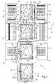
- FIG. 1 a mounting device 1 for mounting hardware components on wing and / or frame of windows, doors or the like is shown. Purely by way of example will be described below how fittings are mounted on the sash of a window.
- the mounting device 1 comprises a plurality, here four assembly stations 2,3,4 and 5, which are connected in the transport direction 7 of a sash 8 in series.
- a transport device or displacement device (not shown here) is provided which, for example, is designed as a conveyor belt or roller conveyor can be.
- movable stops or the like are used, which take the sash and take with him.
- the roller conveyor extends over the entire length of the mounting device 1, wherein at least some rollers of the roller conveyor can be rotationally driven for the transport of the sash 8.
- the assembly device 1 is associated with a processing station for sash 8, in which the individual spars of the sash 8 are connected to each other, so that the sash frame 8 shown in Figure 1 results.
- the mounting device 1 according to Figure 1 is here purely exemplary of the fitting assembly formed for right hinged sash.
- the assembly station 2 magazines 9 and 10 are assigned for the reception and provision of fittings. Accordingly, the assembly station 3 more magazines 11 and 12 are assigned; Finally, the assembly station 4 also has two magazines 13 and 14 assigned to it.
- the guideway 15 extends The guideway 16, however, extends substantially at right angles to the guideway 15.
- Both guideways 15 and 16 are each a feeder 17 and 18 respectively assigned to receive fittings from the magazines 9 and 10 and for supplying the machine gripped fitting parts to the sash 8 are formed.
- the feed devices 17 and 18 are freely displaceable on their associated guide track, so that any desired position on the corresponding guide track 15 or 16 can be assumed by the feed device. With the feed device 17, however, can also be removed from the magazines 11 and 12 fittings.
- the assembly station 3 is associated with a guide track 19 which is substantially parallel to the guide track 16.
- the guideway 19 may also be formed as a so-called NC axis.
- the guideway 19 is associated with a feeder 20, with a fitting part of the magazines 11 and / or 12 can be added and fed to a sash.
- the assembly station 3 is associated with a guide track 21, which extends substantially at right angles to the guide track 19 or is substantially parallel to the transport direction 7.
- the guideway 21 carries a fastening device 22 for fittings, which may be formed in particular as a screw device 23.
- the assembly station 4 are also associated with two guideways 24 and 25, wherein the guideway 24 is substantially perpendicular to the transport direction 7 and the guide track 25 is substantially parallel to the transport direction 7.
- a freely displaceable fastening means 26 is arranged, which may be formed as a screw means 27.
- the guideway 25, however, is associated with a feed device 28 which is freely displaceable along the guideway 25.
- the feeder 28 serves to receive fitting parts from the magazines 13 and 14 and to supply the recorded fittings to a sash.
- the feed devices 17, 18, 20 and 28 can each be designed as gripper devices 29, 30, 31 and 32, which can have a pincer-like gripping unit 33.
- the assembly station 5 are associated with guideways 34 and 35, each carrying a fastening means 36 and 37, respectively, which are freely displaceable along the associated guide track 34 and 35.
- the fastening devices 36 and 37 are preferably designed as screw means 38 and 39, respectively.
- the magazines 9 to 14 shown in FIG. 1 are shown in a so-called refilling position. That is, in the position shown in Figure 1, a loading of the magazines 9 to 14 is provided. In working position, the magazines are 9 to 14 preferably below the sash, in particular below the transport or displacement device not shown here for the sash 8. This also as underfloor arrangement designated positioning of the magazines 9 to 14 is advantageous in that the corresponding feed means 17, 18, 20 and 28 need not perform any unnecessary pivoting movements, since a gripping or receiving the located in the magazines 9 to 14 fitting parts only by tilting the feeder 17, 18, 20 and 28 takes place. However, it is also possible that the magazines are 9 to 14 in the position shown in Figure 1 in the working position.
- the fitting parts are accommodated like a magazine, so that by means of a feed device 17, 18, 20, 28 in each case a single fitting part can be gripped or received. If a fitting part is removed, it is preferably provided that the next fitting part is transported in the removal position. For this purpose, in particular a vibrator or a conveyor may be provided. An inclined plane can also be provided, on which the fitting parts slide into the removal position.
- the fitting parts in the magazines 9 to 14 are mounted so that the respective different fitting parts are substantially adjacent to the later installation on the sash 8, so that here small transport paths or feed paths can be met, whereby the production speed is increased.
- the magazines 9 to 14 are equipped as follows:
- the so-called Axer corner assembly 40 and the Axer corner fitting a first Center lock 41 and a second center lock 42, a corner band 43 optionally with Eckbandêt and a fitting 110 is stored.
- the magazine 10 is preferably equipped like the magazine 9.
- the magazines 13 and 14 are preferably equipped identically, with a gear 48 and a connecting part 49 and a Ablfitteil 50 are stored.
- the assembly of the associated fitting parts on the transverse struts 51 and 53 as well as on the longitudinal bars 52 and 54 of the sash frame 8 will be described below for a tiltable sash 8.
- the casement 8 is fed to the first assembly station 2 and fixed on a processing table, not shown here, so that the longitudinal spar 52 is substantially parallel to the guide track 15.
- the cross member 53 also lies substantially parallel to the guide track 16. In this position, the casement 8 is fixed, so that a movement during fitting assembly is not possible.
- pivotable claws and / or fixed stops can be provided. The number of fixed stops or the pivotable claws can be varied according to the window format, ie the sash length or width.
- grippers or stops can be provided which are designed to be displaceable. These grippers can attack the so-called wing flap and bring the sash 8 in the desired mounting position. In order to prevent distortion or distortion of the sash, the grippers can be mounted in a floating manner. After the grippers have spent the casement 8 in the machining position, the aforementioned pivotable claws are extended, which then press the casement 8 against the hard stops.
- the feeder 18 has already taken an Axer corner fitting 40 from the magazine 9 or 10 and the wing frame 8 fed, in particular inserted into a circumferential groove of the frame 8, and by the feeding the Axer corner fitting 40 prefixed in the circumferential groove of the sash 8, in particular clamped or clipped.
- the first middle part 41 is received by means of the feed device 18 and also positioned in the circumferential groove of the sash frame 8 and the longitudinal spar 52.
- the pre-fixing, ie the clamping or clipping of the second center lock 42 in the longitudinal beam 52 is performed by means of the feed device 18 and also positioned in the circumferential groove of the sash frame 8 and the longitudinal spar 52.
- a corner band lock 43 is removed from the magazine 9 or 10 and pre-fixed to the sash 8, ie clipped or clamped by the feeder 18.
- the feeder 17 takes the gear corner fitting 44 from the magazine 11 and positions it accordingly on the cross member 53.
- the feeder 17 receives the third center lock 45 and guides it to the cross member 53, so that the third center lock 45 is also prefixed.
- a drilling unit can be arranged at the assembly station 2, which is preferably arranged on the guide track 15. With the drilling unit 53 holes for a corner band in the wing flap can be introduced after or before mounting the fitting assemblies on the cross member. Subsequently, the corner belt 110 can be taken from the magazine 9 or 10 and supplied to the casement 8 with the feeder 18.
- the wing frame 8 in the mounting position holding claws are pivoted away, so that the sash 8 is released for transport to the assembly station 3.
- the cross member 51 is also equipped with the gear corner fitting 44 by means of the feeder 20.
- the feed device 20 positions the Axerstulp 46 and the Ablnatureteil 47 on the cross member 51.
- a cutting device preferably a punch.
- the feeder 17 or 20 takes that AblCodeteil 47 from the magazine 12 and pushes it into the cutting device.
- the cutting length is set by the positioning of the feeder 17 or 20 on the guide track 16 or 19. That is, when using NC axes can be determined from the coordinate of the feeder 17 or 20, the Ablnature and set the distance device accordingly.
- a second assembly step the fitting of the fitting parts 40, 41, 42, 43 and 110 by means of the fastening device 22 and the screw means 23, wherein the Axer corner fitting 40 and the corner band 43 only on a leg which is parallel to the guide track 21 to be screwed.
- the second assembly step for the longitudinal beam 52 is thus carried out at the assembly station 3, wherein for the cross member 51 in the assembly station 3, the first processing step, ie the prefixing of the fitting parts is performed.
- the sash 8 can be transported to the assembly station 4, to be subsequently fixed again in a processing position by means of claws or the like.
- the screw means 27 are screwed.
- the assembly of the longitudinal spar 54 with the fitting parts 48, 49 and 50, which selectively from the magazine 13 and / or 14 by means of the feeder 28 and the gripper device 32 can be recorded by machine.
- the Ablfitteil can here, also as in assembly station 3, a supplied at the ends of the guide track 25 stationary Ablteil might be supplied by the feeder 28.
- the cutting length is determined by the travel of the feeder 28 on the guideway 25.
- For the longitudinal beam 54 thus results in the first processing step, ie the prefixing of the fitting parts at the assembly station. 4
- the transport of the sash 8 is performed to the assembly station 5.
- the second processing step then takes place for the longitudinal spar 54 and the transverse spar 53. That is to say, the fitting parts are screwed to the spars 53 and 54 of the casement 8 by means of the wrenching devices 38 and 39.
- the cross member 53 of the second processing step or the second mounting location at the assembly station 5 wherein the first processing step of the cross member 53 has been accomplished at the assembly station 2.
- the gear corner fitting 44 is stored, which is pre-fixed in the corner between the cross member 53 and longitudinal spar 54 by means of the feeder 17.
- the first and second center locks 41 and 42 are stored in magazines, wherein the position relative to the magazines 9 and 10 in the magazine 9 or 10 in FIG. 2 is reversed or mirror-symmetrical. That is, in the magazines 9 and 10 in Figure 2, the corner band 43 is arranged with Eckbandêt above.
- the Axer-corner fitting 40 is stored in the magazine 9 and 10 below.
- the center locks 41 and 42 are also arranged reversed.
- An exchange of stocked magazines 9 to 10 can be particularly easily realized that they are designed as drawers, so that the magazine contains 9 fittings for a right and the magazine 10 fittings for a left wing. Moreover, the magazines 11 to 14 may also be designed as drawers. Thus, the mounting device 1 can be quickly and easily converted from right to left wing frame. Of course, this also applies to a configuration change from left to right wing frame.
- the spars 52 and 53 were equipped with the fitting parts 41, 42, 43, 110 and 40, 44, 47 and 46, carried a transport of the sash 8 to the assembly station 3, at the now the gear corner fitting 44 and the third center piece 45 are prefixed by means of the feed device 20 on the cross member 51.
- the fitting parts are bolted to the longitudinal spar 52 by means of the fastening device 22.
- the sash 8 is transported to the assembly station 4 and there again set in its working position.
- the gear 48, the connecting part 49 and the Abflindteil 50 is prefixed to the longitudinal spar 54, wherein in the magazine 13, the connecting part 49 and the Ablnatureteil 50 are arranged opposite to the magazine 13 in Figure 1 reversed.
- both types of wings can optionally be edited alternately or simultaneously without changing the magazine. This means that, for example, in the assembly station 2 there is a wing frame to be fitted on the left and in the assembly stations 3, 4 and 5 a wing frame to be fitted on the right is finished.
- the gear 48 is offset by a central longitudinal axis M by 180 ° in the magazine 13 in Figure 2.
- the fitting parts 45, 44 and 43 are screwed to the cross member 51, wherein in the fitting parts 43 and 44, only the leg is screwed, which is parallel to the guide rail 24.
- the fitting parts 44, 48, 49 and 50 are screwed, wherein by means of the fastening means 36, the legs of the fitting parts 44 are screwed, which are parallel to the guide track 34. With the fastening device 37 which are parallel to the guideway 35 legs of the fitting parts 44 and 40 are screwed. In addition, the fitting parts 46 and 47 are fixed to the cross member 53 by means of screwing.
- FIG. 3 shows a further exemplary embodiment of a mounting device 1 ', in which the individual assembly stations 2 and 3 lie one behind the other and the assembly stations 4 and 5 are arranged one behind the other, but arranged parallel to the assembly stations 2 and 3 are.
- the guideways for the feeders and the fasteners are arranged in this embodiment of the mounting device 1'nchförmig.
- the guideways 15 and 34 are therefore parallel to each other.
- the guideways 16 and 17 are parallel to each other and preferably have an angle of 90 ° relative to the guideway 15 and 34, respectively.
- the guideways 21 and 25 are parallel to each other and are arranged at an angle of 90 ° to the guideways 16 and 17.
- the guideway 24 and the guideway 35 are parallel to each other and close with the guideway 15 and 34 an angle of 90 °.
- the same parts as in Figures 1 and 2 are provided with the same reference numerals. In this respect, reference is made to their description.
- a sash 8 for right stop In the mounting device 1 ' is exemplified here a sash 8 for right stop. Of course, however, left-wing sash to be fitted with fittings can be fitted.
- an adaptation of the magazines, not shown here in FIG. 3 can then take place.
- the magazines are preferably underfloor, so under a transport device, not shown here, on which the sash 8 rests arranged.
- Figure 4 shows a third embodiment of a mounting device 1 ', which differs from the embodiment 1' in Figure 3 differs in that the guideways are arranged so that when transported in the direction of arrow 7 '' of the sash 8 no guideway must be run over.
- This is advantageous in that it does not have to take into account the position of a gripper or a feed device and a fastening device or a screw device. That is, the sash 8 can already be transported to the next assembly station, although the feeder and fixing device are not yet in a basic position.
- the equipment of the guideways with a feeder or a fastening device is shown in Figure 4, characterized in that a guideway with a gripper with G and a guideway with a screw device with S is marked. Accordingly, in the first two assembly stations 2 and 3 of the sash 8 is equipped with the fittings and in the assembly stations 4 and 5, these fittings are then screwed.
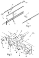
- FIG. 5 shows a feed device 17, which is designed as a gripper device 29.
- the gripper device 29 has a plurality of grippers 55, which are spaced from each other, but are arranged in series.
- Each gripper 55 has two gripping fingers 56, so that two gripping fingers 56 form a pincer-like gripping unit 33.
- each gripping unit 33 is pneumatically actuated. Of course, any other suitable drive be used.
- the entire feed device 17 is movably guided on the guide track 15, as indicated by a double arrow 57.
- the gripper device 29 is pivotally mounted about the guide track 15, as indicated by the double arrow 58.
- the pivoting radius or the pivoting angle of the gripper device 29 preferably comprises 90 °, so that -aus obtainedd of the horizontal position shown in Figure 5 is a Vornekippen by 90 ° is possible, so that the gripper 55 can grip a below them fitting part and record.
- either all three grippers 55 are operated or required or only one gripper or two grippers.
- the middle closure 41 shown in FIG. 7, which is relatively long preferably all three grippers 55 are used.
- the grippers 55 are movable on a gripper bed 59 in the direction of arrow 60.
- This is advantageous in that the Axer corner fitting 40 is gripped at its leg 15 parallel to the guide rail and inserted into the circumferential groove of the sash 8.
- a fitting part present in the magazine is slightly raised by a lifting device in the magazine, so that a particularly simple gripping and separating is possible.
- the fitting parts 41 located in the magazine are therefore in position A.
- a fitting part 41 is then conveyed out in the direction of arrow B from the magazine.
- the gripper device 29 is tilted in the direction of arrow 58 ( Figure 5) down, so that when tilting back the gripper device 29 in the direction of arrow 58, the fitting 41 is brought according to arrow direction C and C 'in feed position.
- a subsequent method of gripper device 29 in the direction of arrow 57 brings the fitting 41 in the corresponding position to the spar of the sash.
- the fitting part 41 is inserted into the circumferential groove of the sash and clamped or clipped.
- FIG. 6 shows in detail a gripper 55 with a gripped fitting part, which here is, for example, the gearbox corner fitting 44.
- the gripping fingers 56 engage in a shaping feature 62 on the fitting 44.
- the shape feature 62 is here a slot 62 ', which is penetrated by a mushroom pin 63.
- the gripping fingers 56 are formed such that they engage with a projection 65 in the shape feature 62, ie in the slot 62 '.
- the gripping fingers 56 a hammer-like extension 66, so that an investment with the face-plate 67 of the fitting 44 is formed. As a result, the fitting 44 is held securely and can not tip over.
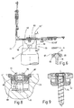
- FIG. 8 shows a sectional view of an inserted into the circumferential groove 68 of the casement 8 fitting part is reproduced, which has a lower faceplate 69 and an upper faceplate 67.
- the cuff rails 67 and 69 each have an opening 70 or 71 through which at least partially passes a Einklipsteil 72.
- a Klips driven 73 On the lower faceplate 69 side facing the Einklipsteil 72 a Klips liked 73, which with the side walls the circumferential groove 68 cooperates.
- Figures 10 and 11 each show an embodiment of a complete set of fittings 75 for sash, in Figure 10, a so-called integral central closure is shown with large assemblies.
- the fitting set 75 according to FIG. 10 has a corner deflection 76, a transmission corner deflection 78 with a turn-tilt bearing 77.
- the set of fittings 75 comprises a so-called Axerstulp 79, a vertical middle closure 80, a horizontal middle closure 81 and a Eckbandêt 82.
- the fitting parts of the fitting set 75 may be stored for mechanical assembly in the magazines 9 to 14, so that they by means of a gripper or feeder gripped and the sash 8 can be supplied.
- the fitting set 75 according to Figure 11 is designed as a so-called modular central closure and is preferably intended for fully automatic assembly.
- the same parts as in FIG. 10 are given the same reference numerals.
- the Drehkipp transmission 78 is divided into a plurality of assemblies 83, 84 and 85, so that a Drehkipp gear 78 for different wing frame formats Use finds.
- assemblies 83, 84 and 85 are provided, the assembly 83 is provided as a coupling part between the transmission corner 77 and the Drehkipp transmission 78.
- the assembly 84 is an intermediate part, which connects the Drehkipp gear 78 with the Eckumlenkung 76 via a Abl Kunststoffteil (assembly 85).
- the Axerstulp 79 is formed in the embodiment of Figure 5 by the Axer assembly 86 and formed as AblCodeteil intermediate piece 87.
- the Axerstulp is also associated with an Axer-Eckumlenkung 88.
- the Axerstulp 79 can be used for each wing width, since the actual adaptation to the wing format can be made by means of the AblCodeteil 87.
- the movable gear parts of the fittings can be coupled via basically known coupling devices 89 and 90, so that a power transmission can take place.
- a coupling device 91 is shown, wherein at the corner deflection 77, a cranked drive rod 69 'is provided, which is equipped with a coupling pin 92 at its one end.
- a faceplate 67 also has a coupling pin 93. Both coupling pins 92 and 93 enter into a corresponding recess or an opening 94 or 95, so that a mechanical connection is realized.
- the opening 95 is associated with a drive rod 69 '' of a straight fitting part.
- the opening 94 is associated with a faceplate 67 'of the straight fitting part.
- FIG. 13 shows an exemplary embodiment of a coupling part 91 '.
- the coupling part 91 ' has a stabilizing device 96, which may be U-shaped and is arranged on the drive rod 69' of the transmission corner drive 77.
- the stabilizing member 96 engages at a distance from the coupling pin 92, the drive rod 69 '' at least partially, so that a rotation between drive rod 69 'and drive rod 69' 'is given.
- a secure power transmission is ensured.
- FIG. 14 the removal of a corner fitting, in particular a corner deflection 97, is described by way of example.
- Several Eckumlenkungen 97 are held upright in a magazine.
- the magazine has a lifting device, with each of which located in the dispensing position Eckband 97 can be easily lifted.
- At the leg 97 'of the corner band 97 attacks at least one gripper, which pivots in its backward movement, in particular a pivoting movement - in accordance with arrow direction 58 in Figure 5- the corner band 97 by approximately 90 °.
- a height adjustment of the gripper takes place, so that the corner band 97 has the same height as the circumferential groove on the casement.
- the legs 97 'and 97 "of the corner fitting 97 are aligned with the circumferential groove.
- the corner band 97 is positioned according to the casement or so far introduced into the circumferential groove that it snaps or clipped or pinched becomes.
- the leg 97 ' is introduced into the section of the circumferential groove assigned to it.
- both legs 97 'and 97''of the corner band 97 are in the circumferential groove. That is, the corner fitting 97 is pre-fixed and provided for a subsequent screwing.
- the assembly of the fittings is thus characterized by an optional or mixed placement of corner assemblies and fasteners, for example, center locks, starting with a corner assembly on a wing corner, from. All fitting components for each wing spar are completely prefixed to the wing. Due to the arrangement of the coupling points, the preferred sequence of fitting assembly assembly on the individual wing spars begins at each wing corner with the corner assembly, followed by the next required connecting element until the required components for the closing function on the wing leg or wing spar are coupled and pre-fixed. Individual parts or assemblies not arranged in the drive rod assembly can optionally be attached to the best matching in the assembly process points on the wing.
- the assembly is characterized by the separation of fitting prefixing by clamping or clipping and a subsequent automatic screwing as a very flexible and inexpensive mounting system, where it is possible, among other things, all screwing in one step, preferably at the end of the module pre-fixing merge.
- the screw positions are preferably controlled variably and quickly by means of programmable axes. This comparatively the machine cost is kept low in terms of the number of screwing or screwing and reduced installation time by immediate release of the gripper after pre-fixing of the modules.
- the method is also characterized by a high degree of flexibility in the design of the assembly sequence, whereby it is also possible to integrate in the individual assembly stages each individual screwdriver operations. For this purpose, for example, it is provided that a gripper device 29 (FIG.
- the individual assembly work steps can be coordinated with each other very precisely in terms of time so as not to increase the cycle time of individual assembly steps more than the cycle time of a mounting stage preceding the assembly device 1.
- the wing frame is assembled with its respective bars in this upstream assembly stage.
- the cycle time is for example one minute. Due to the separation of fitting pre-fixing and fitting screwing, it is also possible to integrate ancillary activities in individual assembly stages, such as, for example, drilling of the corner band holder. Due to the arrangement-related editing on two wing spars at the same time, can be at each processing station Place part of the assembly work steps in the assembly time.
- both wing spars can be fitted one behind the other, but preferably in pairs, ie at the same time.
- each assembly station so at least two wing spars are simultaneously in the edit mode, for example, prefixed to two wing beams or bolted to a wing spar and prefixed to another wing spar. It is also conceivable that the fitting parts are screwed simultaneously on both bars.
- the assembly method according to the invention thus allows the installation of the entire fitting set on the casement and window door leaf in an assembly line.
- a movable, in particular height-adjustable, table segment is arranged between two processing stations or assembly stations. This means that especially small sashes can be transported between two assembly stations.
- a window sash 8 ( Figure 1) was processed at the assembly station 2 and was further transported to the assembly station 3 - a new or further sash of the assembly station 2 is supplied.
- the preferred assembly process is such that always four wings are simultaneously in the mounting device 1, 1 'and 1' 'in progress.
- each corner assembly is optimally designed according to their function.
- various corner assemblies can be mounted, which are stored in the magazines.
- Eckbau jury be used.
- a gripper device 29 still has a Eindrücknocken for the prefixing of the corner assemblies.
Landscapes
- Engineering & Computer Science (AREA)
- Mechanical Engineering (AREA)
- Manufacturing & Machinery (AREA)
- Door And Window Frames Mounted To Openings (AREA)
- Joining Of Corner Units Of Frames Or Wings (AREA)
- Hinges (AREA)
Claims (16)
- Procédé pour le montage mécanique de ferrures sur des châssis de battant et/ou dormants de fenêtres, de portes ou similaires comportant les étapes suivantes :- dans une première étape de traitement, au moins une ferrure saisie mécaniquement est amenée à un montant du châssis de battant et/ ou du dormant situé à un premier emplacement de montage et de cette manière, est préfixé en position prédéfinie sur le châssis par clipsage par friction ou par pressage par friction dans une rainure périphérique du châssis de battant/ de la feuillure du dormant,- ensuite le châssis est amené à un autre emplacement de montage, et- lors d'une deuxième étape de traitement, la ferrure est vissée mécaniquement au montant.
- Procédé selon la revendication 1,
caractérisé en ce que
la ferrure saisie mécaniquement peut être déplacée librement le long de l'axe longitudinal du montant. - Procédé selon l'une quelconque des revendications précédentes,
caractérisé en ce qu'
un dispositif de vissage effectuant le vissage mécanique peut être déplacé librement parallèlement à l'axe longitudinal du montant. - Procédé selon l'une quelconque des revendications précédentes,
caractérisé en ce que
le montage de ferrures commençant par une zone d'angle du châssis a lieu en direction d'un angle voisin du châssis. - Procédé selon l'une quelconque des revendications précédentes,
caractérisé en ce que
le montage des ferrures a lieu de telle sorte que lors de l'amenée d'une ferrure à un endroit adjacent à une ferrure déjà amenée, l'accouplement des deux ferrures ait lieu automatiquement et simultanément. - Procédé selon l'une quelconque des revendications précédentes,
caractérisé en ce qu'
une ferrure réalisée en tant que ferrure angulaire est amenée de telle sorte que tout d'abord une branche de la ferrure angulaire pénètre dans une section de la rainure périphérique du châssis de battant/de la feuillure du dormant et que l'autre branche pénètre en même temps par déplacement parallèle à l'axe longitudinal du montant dans la section respective de la rainure périphérique du battant/de la feuillure du dormant qui lui est associée. - Procédé selon l'une quelconque des revendications précédentes,
caractérisé en ce qu'
une ferrure réalisée en tant que ferrure angulaire est amenée de telle sorte que les deux branches de la ferrure angulaire pénètrent simultanément dans les sections respectives de la rainure périphérique du châssis de battant/de la feuillure du dormant. - Procédé selon l'une quelconque des revendications précédentes,
caractérisé en ce que
pour l'amenée de la ferrure, la saisie mécanique se fait au niveau d'une caractéristique de forme. - Procédé selon l'une quelconque des revendications précédentes,
caractérisé en ce que
les ferrures à monter sont prélevées mécaniquement au moins d'une réserve. - Procédé selon l'une des revendications précédentes,
caractérisé en ce que
la position de prélèvement de la ferrure est toujours identique grâce à la possibilité de déplacement de la réserve. - Dispositif, en particulier pour la réalisation du procédé selon l'une quelconque des revendications 1 à 10, pour le montage mécanique de ferrures sur des châssis de battant et/ou dormants de fenêtres, portes ou similaires, avec un dispositif d'amenée mécanique (17, 18, 20, 28) et un dispositif de fixation mécanique (22, 26, 36, 37), dont le dispositif d'amenée (17, 18, 20, 28) adapté aux ferrures est associé à une première station de montage (2, 3, 4, 5) et le dispositif de fixation (22, 26, 36, 37) adapté aux mêmes ferrures amenées précédemment est associé à une deuxième station de montage (2, 3, 4 5), et avec un dispositif de déplacement mécanique qui transfère le châssis (8) de la première à la deuxième station de montage (2, 3, 4 ,5).
- Dispositif selon la revendication 11,
caractérisé en ce que
le dispositif d'amenée (17, 18, 20, 28) est un dispositif à préhenseurs (29, 30, 31, 32), un dispositif à dépression et/ou un dispositif magnétique. - Dispositif selon l'une quelconque des revendications 11 et 12,
caractérisé en ce que
le dispositif à préhenseurs (29, 30, 31, 32) est guidé par déplacement libre le long de l'axe longitudinal d'au moins un montant (51, 52, 53, 54) du châssis du battant et/ou du dormant. - Dispositif selon l'une quelconque des revendications 11 et 13,
caractérisé en ce que
le dispositif de fixation (22, 26, 36, 37) est guidé par déplacement libre le long de l'axe longitudinal d'au moins un montant (51, 52, 53, 54) du châssis du battant et/ou du dormant. - Dispositif selon l'une quelconque des revendications 11 à 14,
caractérisé en ce que
le dispositif de fixation (22, 26, 36, 37) est un dispositif de vissage (23, 27,38,39). - Dispositif selon l'une quelconque des revendications 11 à 15,
caractérisé en ce que
le dispositif de déplacement déplace le châssis de battant et/ou le dormant perpendiculairement, en particulier de 90° par rapport à l'étirement longitudinal de ce montant (51, 53).
Applications Claiming Priority (2)
| Application Number | Priority Date | Filing Date | Title |
|---|---|---|---|
| DE19843269 | 1998-09-21 | ||
| DE1998143269 DE19843269A1 (de) | 1998-09-21 | 1998-09-21 | Verfahren zur maschinellen Montage von Beschlagteilen an Flügel- und/oder Blendrahmen von Fenstern, Türen oder dergleichen und Vorrichtung zur maschinellen Montage von Beschlagteilen an Flügel- und/oder Blendrahmen von Fenstern, Türen oder dergleichen |
Publications (3)
| Publication Number | Publication Date |
|---|---|
| EP0988922A2 EP0988922A2 (fr) | 2000-03-29 |
| EP0988922A3 EP0988922A3 (fr) | 2002-05-22 |
| EP0988922B1 true EP0988922B1 (fr) | 2007-01-10 |
Family
ID=7881726
Family Applications (1)
| Application Number | Title | Priority Date | Filing Date |
|---|---|---|---|
| EP99118227A Revoked EP0988922B1 (fr) | 1998-09-21 | 1999-09-14 | Procédé et dispositif de montage automatique des ferrures sur les ailes et/ou dormants des fenêtres, portes ou similaires |
Country Status (2)
| Country | Link |
|---|---|
| EP (1) | EP0988922B1 (fr) |
| DE (2) | DE19843269A1 (fr) |
Families Citing this family (8)
| Publication number | Priority date | Publication date | Assignee | Title |
|---|---|---|---|---|
| DE19952492B4 (de) * | 1999-10-30 | 2004-11-04 | Roto Frank Ag | Vorrichtung und Verfahren zur maschinellen Montage von Beschlagteilen an Flügel- und/oder Blendrahmen von Fenstern, Türen oder dergleichen |
| DE10125803B4 (de) * | 2001-05-26 | 2005-02-24 | Roto Frank Ag | Treibstangenbeschlag-Montagesatz, entsprechendes Dreh-Kipp-Fenster oder -Tür und Verfahren zur Montage eines derartigen Montagesatzes |
| DE10212202A1 (de) * | 2002-03-19 | 2003-10-02 | Afs Holding Gmbh | Vorrichtung zur automatischen Montage von Flügelbeschlagteilen |
| FR2911808B1 (fr) * | 2007-01-25 | 2010-04-23 | Cyrus Bruno Hassan Moini | Poste de ferrage de menuiseries et procede correspondant |
| CN110682390A (zh) * | 2019-08-20 | 2020-01-14 | 台州市意利欧机械有限公司 | 一种组框机 |
| CN113385588A (zh) * | 2021-05-14 | 2021-09-14 | 安徽美沃门窗科技有限公司 | 一种便于维修的铝合金门窗加工用撞角机 |
| CN114932408B (zh) * | 2022-06-24 | 2024-02-09 | 圣奥科技股份有限公司 | 一种板式整装柜自动化组装方法及生产线 |
| CN117140027B (zh) * | 2023-10-16 | 2024-04-12 | 山东雷德数控机械股份有限公司 | 一种门窗组角生产线及工作方法 |
Citations (2)
| Publication number | Priority date | Publication date | Assignee | Title |
|---|---|---|---|---|
| DE4417818A1 (de) * | 1994-05-20 | 1995-11-23 | Winkhaus Fa August | Verfahren zur montageautomaten-unterstützten Montage von Beschlagsteilen an den Flügel eines Fensters, einer Tür o. dgl. |
| DE29803656U1 (de) * | 1998-03-03 | 1998-04-23 | Wilhelm Weidtmann GmbH & Co KG, 42551 Velbert | Tür- oder Fensterbeschlag |
Family Cites Families (3)
| Publication number | Priority date | Publication date | Assignee | Title |
|---|---|---|---|---|
| FR2647846B1 (fr) * | 1989-06-01 | 1995-04-14 | Ferco Int Usine Ferrures | Installation pour la finition de chassis de fenetres |
| FR2659040B1 (fr) * | 1990-03-02 | 1992-05-15 | Ferco Int Usine Ferrures | Machine automatique de pose de composants sur dormants de porte ou fenetres. |
| FR2662107B1 (fr) * | 1990-05-21 | 1993-06-25 | Ferco Int Usine Ferrures | Machine automatique de pose de gaches sur des dormants de fenetres ou de porte-fenetres. |
-
1998
- 1998-09-21 DE DE1998143269 patent/DE19843269A1/de not_active Withdrawn
-
1999
- 1999-09-14 DE DE59914140T patent/DE59914140D1/de not_active Expired - Lifetime
- 1999-09-14 EP EP99118227A patent/EP0988922B1/fr not_active Revoked
Patent Citations (2)
| Publication number | Priority date | Publication date | Assignee | Title |
|---|---|---|---|---|
| DE4417818A1 (de) * | 1994-05-20 | 1995-11-23 | Winkhaus Fa August | Verfahren zur montageautomaten-unterstützten Montage von Beschlagsteilen an den Flügel eines Fensters, einer Tür o. dgl. |
| DE29803656U1 (de) * | 1998-03-03 | 1998-04-23 | Wilhelm Weidtmann GmbH & Co KG, 42551 Velbert | Tür- oder Fensterbeschlag |
Also Published As
| Publication number | Publication date |
|---|---|
| EP0988922A3 (fr) | 2002-05-22 |
| DE59914140D1 (de) | 2007-02-22 |
| EP0988922A2 (fr) | 2000-03-29 |
| DE19843269A1 (de) | 2000-03-30 |
Similar Documents
| Publication | Publication Date | Title |
|---|---|---|
| EP0683297B1 (fr) | Procédé de montage assisté par automate des ferrures sur une aile d'une fenêtre, porte ou similaire | |
| EP2340147B1 (fr) | Machine d'usinage pour usinage de six faces | |
| DE19621658C2 (de) | Bearbeitungsmaschine für plattenförmige Werkstücke, insbesondere zur Erzeugung von gebogenen Rändern an Blechteilen | |
| EP0123183B1 (fr) | Machine d'usinage pour des pièces plates | |
| DE4408449A1 (de) | Transportsystem | |
| AT514821B1 (de) | Biegepresse und Biegeverfahren | |
| EP3031547B1 (fr) | Procede et dispositif de fabrication d'un raccord d'angle | |
| EP3357617A1 (fr) | Machine d'usinage de profilé et ligne d'usinage de profilé | |
| EP0925868A2 (fr) | Dispositif de fabrication de châssis de fenêtres | |
| EP1600254A1 (fr) | Unité d'avance pour machine à usiner des pièces et méthode pour usiner ces pièces | |
| DE4232289C2 (de) | Verfahren und Vorrichtung zum Verschwenken eines Fensterrahmens im Bereich einer Eckenputzmaschine | |
| EP0249946B2 (fr) | Procédé et dispositif pour la fabrication d'un cadre d'espacement pour vitres isolantes | |
| EP0988922A2 (fr) | Procédé et dispositif de montage automatique des ferrures sur les ailes et/ou dormants des fenêtres, portes ou similaires | |
| DE19725627B4 (de) | Drehkipp-Beschlag-System | |
| DE69008120T2 (de) | Vorrichtung zur stufenweisen Positionierung, Bearbeitung und Nachbehandlung von Ecken von aus Kunststoff hergestellten Fenster- oder Türrahmen in einer seitlich angeordneten Arbeitsstelle. | |
| DE19952492B4 (de) | Vorrichtung und Verfahren zur maschinellen Montage von Beschlagteilen an Flügel- und/oder Blendrahmen von Fenstern, Türen oder dergleichen | |
| EP0925126B1 (fr) | Machine a usiner des plats dotee d'une serre-flan reparti en segments | |
| DE60104460T2 (de) | Steuereinheit für Fensterrahmen, Verfahren zu seiner Herstellung und Maschine zum Durchführen des Verfahrens | |
| DE3203025A1 (de) | Verfahren und vorrichtung zur herstellung von fensterrahmen und -fluegeln aus kunststoff | |
| DE60114695T2 (de) | Wringvorrichtung und Folgewerkzeug mit solcher Vorrichtung | |
| DE60202084T2 (de) | Verfahren zur Herstellung von Treibstangen von Griffeinheiten für Fensterrahmen und Gerät zum Durchführen des Verfahrens | |
| DE69414395T2 (de) | Verfahren zur bearbeitung von hohlprofilen, zur formung von rahmen und entsprechende rahmen und hohlprofile | |
| EP1377395B1 (fr) | Machine de pliage, en particulier presse a estamper ou a plier, pourvue d'un outil inferieur reglable | |
| DE60103204T2 (de) | Verfahren zum Bearbeiten von Rahmenprofilen von Türen oder Fenstern und damit übereinstimmende Maschine zum Bearbeiten von Rahmen- und Flügelprofilen von Türen oder Fenstern | |
| DE102006036193B4 (de) | Vorrichtung und Verfahren zur Montage eines Möbelkorpus |
Legal Events
| Date | Code | Title | Description |
|---|---|---|---|
| PUAI | Public reference made under article 153(3) epc to a published international application that has entered the european phase |
Free format text: ORIGINAL CODE: 0009012 |
|
| AK | Designated contracting states |
Kind code of ref document: A2 Designated state(s): AT BE CH CY DE DK ES FI FR GB GR IE IT LI LU MC NL PT SE |
|
| AX | Request for extension of the european patent |
Free format text: AL;LT;LV;MK;RO;SI |
|
| PUAL | Search report despatched |
Free format text: ORIGINAL CODE: 0009013 |
|
| AX | Request for extension of the european patent |
Free format text: AL;LT;LV;MK;RO;SI |
|
| 17P | Request for examination filed |
Effective date: 20020815 |
|
| AKX | Designation fees paid |
Designated state(s): AT CH DE FR IT LI |
|
| 17Q | First examination report despatched |
Effective date: 20031006 |
|
| GRAP | Despatch of communication of intention to grant a patent |
Free format text: ORIGINAL CODE: EPIDOSNIGR1 |
|
| GRAS | Grant fee paid |
Free format text: ORIGINAL CODE: EPIDOSNIGR3 |
|
| GRAA | (expected) grant |
Free format text: ORIGINAL CODE: 0009210 |
|
| AK | Designated contracting states |
Kind code of ref document: B1 Designated state(s): AT CH DE FR IT LI |
|
| REG | Reference to a national code |
Ref country code: CH Ref legal event code: NV Representative=s name: E. BLUM & CO. AG PATENT- UND MARKENANWAELTE VSP |
|
| REF | Corresponds to: |
Ref document number: 59914140 Country of ref document: DE Date of ref document: 20070222 Kind code of ref document: P |
|
| ET | Fr: translation filed | ||
| PLBI | Opposition filed |
Free format text: ORIGINAL CODE: 0009260 |
|
| PLAX | Notice of opposition and request to file observation + time limit sent |
Free format text: ORIGINAL CODE: EPIDOSNOBS2 |
|
| 26 | Opposition filed |
Opponent name: AUGUST WINKHAUS GMBH & CO. KG Effective date: 20071001 |
|
| PLBB | Reply of patent proprietor to notice(s) of opposition received |
Free format text: ORIGINAL CODE: EPIDOSNOBS3 |
|
| RDAF | Communication despatched that patent is revoked |
Free format text: ORIGINAL CODE: EPIDOSNREV1 |
|
| APBM | Appeal reference recorded |
Free format text: ORIGINAL CODE: EPIDOSNREFNO |
|
| APBP | Date of receipt of notice of appeal recorded |
Free format text: ORIGINAL CODE: EPIDOSNNOA2O |
|
| APAH | Appeal reference modified |
Free format text: ORIGINAL CODE: EPIDOSCREFNO |
|
| APBQ | Date of receipt of statement of grounds of appeal recorded |
Free format text: ORIGINAL CODE: EPIDOSNNOA3O |
|
| PGFP | Annual fee paid to national office [announced via postgrant information from national office to epo] |
Ref country code: DE Payment date: 20130924 Year of fee payment: 15 Ref country code: AT Payment date: 20130919 Year of fee payment: 15 Ref country code: CH Payment date: 20130923 Year of fee payment: 15 |
|
| REG | Reference to a national code |
Ref country code: DE Ref legal event code: R103 Ref document number: 59914140 Country of ref document: DE Ref country code: DE Ref legal event code: R064 Ref document number: 59914140 Country of ref document: DE |
|
| PGFP | Annual fee paid to national office [announced via postgrant information from national office to epo] |
Ref country code: IT Payment date: 20130926 Year of fee payment: 15 |
|
| APBU | Appeal procedure closed |
Free format text: ORIGINAL CODE: EPIDOSNNOA9O |
|
| PGFP | Annual fee paid to national office [announced via postgrant information from national office to epo] |
Ref country code: FR Payment date: 20130918 Year of fee payment: 15 |
|
| RDAG | Patent revoked |
Free format text: ORIGINAL CODE: 0009271 |
|
| STAA | Information on the status of an ep patent application or granted ep patent |
Free format text: STATUS: PATENT REVOKED |
|
| REG | Reference to a national code |
Ref country code: CH Ref legal event code: PL |
|
| 27W | Patent revoked |
Effective date: 20131205 |
|
| REG | Reference to a national code |
Ref country code: DE Ref legal event code: R107 Ref document number: 59914140 Country of ref document: DE Effective date: 20140410 |
|
| PG25 | Lapsed in a contracting state [announced via postgrant information from national office to epo] |
Ref country code: LI Free format text: LAPSE BECAUSE OF THE APPLICANT RENOUNCES Effective date: 20070110 Ref country code: CH Free format text: LAPSE BECAUSE OF THE APPLICANT RENOUNCES Effective date: 20070110 |
|
| REG | Reference to a national code |
Ref country code: AT Ref legal event code: MA03 Ref document number: 351066 Country of ref document: AT Kind code of ref document: T Effective date: 20131205 |