EP0988980A2 - Imprimante ligne par ligne comportant une perméance magnétique réduite - Google Patents
Imprimante ligne par ligne comportant une perméance magnétique réduite Download PDFInfo
- Publication number
- EP0988980A2 EP0988980A2 EP99307559A EP99307559A EP0988980A2 EP 0988980 A2 EP0988980 A2 EP 0988980A2 EP 99307559 A EP99307559 A EP 99307559A EP 99307559 A EP99307559 A EP 99307559A EP 0988980 A2 EP0988980 A2 EP 0988980A2
- Authority
- EP
- European Patent Office
- Prior art keywords
- pole pieces
- line printer
- magnet
- magnets
- pole
- Prior art date
- Legal status (The legal status is an assumption and is not a legal conclusion. Google has not performed a legal analysis and makes no representation as to the accuracy of the status listed.)
- Withdrawn
Links
Images



Classifications
-
- B—PERFORMING OPERATIONS; TRANSPORTING
- B41—PRINTING; LINING MACHINES; TYPEWRITERS; STAMPS
- B41J—TYPEWRITERS; SELECTIVE PRINTING MECHANISMS, i.e. MECHANISMS PRINTING OTHERWISE THAN FROM A FORME; CORRECTION OF TYPOGRAPHICAL ERRORS
- B41J2/00—Typewriters or selective printing mechanisms characterised by the printing or marking process for which they are designed
- B41J2/22—Typewriters or selective printing mechanisms characterised by the printing or marking process for which they are designed characterised by selective application of impact or pressure on a printing material or impression-transfer material
- B41J2/23—Typewriters or selective printing mechanisms characterised by the printing or marking process for which they are designed characterised by selective application of impact or pressure on a printing material or impression-transfer material using print wires
- B41J2/235—Print head assemblies
- B41J2/245—Print head assemblies line printer type
Definitions
- the field of this invention lies within the field of dot matrix printers. More particularly, the field lies within the art of dot matrix printers which are characterized as line printers having a series of hammers that are released from a hammerbank.
- the hammerbank has permanent magnets for retention of the hammers, and electrical coils to overcome the magnetic retention by reversing the polarity for releasing the hammers. It particularly relates to that aspect of the magnetics which permanently retain the hammers and interact with adjacent magnetic forces including those of the pole pieces.
- the pole pieces can be oriented so as to have shunts and air gaps for modifying the action of the permanent magnets.
- permanent magnetism is provided by a magnet which is placed in a notch, space, or slot between pairs of pole pieces. The magnetism flows from the permanent magnet through the pair of pole pieces for retracting the hammer against the pole pieces.
- Coils are wrapped around the pole pieces and overcome the permanent magnetism of the magnetic circuit so that a release of the sprung hammers of the hammerbank can be effected. This is when the permanent magnetism is counteracted so that the hammers are released and move away by their spring action from the ends of the pole pieces. During this release action, the permanent magnetism and the reverse flux provided by the coils creates a dynamic within the interaction of the hammers and the interfacing adjacent pole pieces. This interaction within the hammers is such that magnetic phenomena dynamically changes between the hammers, the pole pieces, and the magnetic circuit.
- the dynamic interaction is extremely critical to the phases of printing.
- the relative phases of printing as the hammers each respectively strike the print ribbon and the underlying media, can vary depending on the magnetic interaction between adjacent hammers and pole pieces.
- the dots in a line matrix printing or other dot matrix printer are not accurate and do not present clear print. This is most critical with regard to such items today as bar codes that are printed onto an underlying media for bar code reading.
- the foregoing cascading effect can vary depending upon the dynamics of operation. For instance, if one particular series of adjacent springs are releasing and retracting, they can effectively create a cascade effect in an adjacent relationship. To this extent, they can change the magnetic effects on a constantly shifting basis. As a consequence, if this problem can be resolved or reduced it is eminently helpful to the accuracy and functions of a printer, especially a printer printing bar codes.
- the magnetic flux can transit or leap from one pole piece to a neighboring pole piece or pole pin.
- This permeance is inversely proportional to the distance between the pole pieces. In other words the farther they are away in spacing, the less the permeance and effect of mutual inductance has on the magnetic circuits. Further to this extent, the permeance is directly proportional to the adjacent or facing areas of neighboring pole pins or pole pieces. In other words, as the adjoining or adjacent area of the pole pieces increases, there is a directly proportional increase of magnetic permeance between the pole pieces or pins.
- the surface areas are diminished.
- the magnetics provided by the permanent magnet are split.
- the split magnet is interconnected by a keeper in order to provide for connected magnetic functions through the magnetic circuit.
- this invention specifically reduces the geometry of the pole pins as to their mutual facing areas, and reduces self and mutual inductance through the reduction of permeance. In this manner, faster circuits are achieved that are better matched for the timing and voltage levels to allow for less energy per stroke to be consumed from the power supply and more accurate printing. As a consequence, this invention is a broad step over the prior art by increasing speed and accuracy of printing as well as reducing the power requirements.
- this invention comprises a new orientation for the permanent magnets of a line printer and the respective pole pieces enhanced by reducing interfacing areas between pole pieces to reduce permeance while at the same time providing a permanent magnet that has been split for connection thereto held by a magnetically conductive keeper.
- the invention comprises a line printer having pole pieces.
- the pole pieces retain a hammer having a pin thereon for impingement against a print ribbon to print a dot on an underlying media.
- the pole pieces are reduced in overall size and particularly as to their facing areas. By reducing the facing areas, the respective permeance between them is also reduced.
- each pole piece Attached to each pole piece is a permanent magnet that has been split so as to provide continuity of a magnetic circuit.
- the magnet splitting is enhanced by a keeper which maintains the magnetic circuit with proper flow characteristics while at the same time reducing the amount of permeance between the respective pole pieces.
- a further enhancement is the reduction in power consumption, and greater relative control of the hammers of the hammerbank is effectuated to a more finite degree.
- this invention is a substantial step over the prior art as to both design, inventive configuration and attendant operational features as will be seen in the following specification.
- Figure 1 shows a fragmented perspective view of a hammerbank of a line printer showing two hammers and the ends of the pole pieces of this invention.
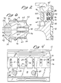
- Figure 2 shows a sectional view of the hammerbank, permanent magnets and coils with a hammer.
- Figure 3 shows an enlarged sectional view of the invention hereof with the pole pieces having a reduced area, and wherein the hammer has been released for purposes of printing.
- Figure 4 shows a fragmented front elevation view of the hammerbank of this invention.
- Figure 5 shows a perspective view of the internal portions of the pole pieces, split magnets, keepers, and hammers of the hammerbank of this invention.
- Figure 6 shows a sectional schematic view of the prior art and the relative facing areas of the pole pieces that exist between respective pole pieces that has been reduced by this invention.
- Figure 7 shows the prior art of the invention analogous to that seen in Figure 6 without the schematic reduction of the facing surface area.
- Figure 8 shows a side sectional elevation view of the invention hereof with the split magnets and keepers in place.
- a hammerbank portion in the form of a fragmented segment toward the end of the hammerbank is shown.
- the fragmented portion of the hammerbank is a segment that is cut from an elongated hammerbank having approximately anywhere from forty to one hundred print hammers more or less that can be retained and then fired or released against a print ribbon as is well known in the art.
- the hammerbank 10 is such wherein the base or shuttle is generally machined or cut from an elongated metal portion such as an aluminum casting or extrusion, or formed in any other suitable manner to provide for an elongated mounting of the hammers on the hammerbank.
- the hammerbank has an area 12 which can receive an elongated circuit board or other controlling means such as in U.S. Patent No. 5,743,665 dated April 8, 1998.
- the hammerbank has an elongated channel or groove 14 which receives the split permanent magnets of this invention as will be described hereinafter.
- hammers 16 can comprise a series of hammers 16 connected to and formed on a fret 18.
- the fret 18 is secured to the hammerbank by screws, nuts or bolts or any other securement means shown generally as screw 20.
- an indexing pin 22 is provided in order to allow a slotted portion 24 of the fret 18 to be indexed thereagainst for securement.
- the hammers 16 comprise an enlarged portion 26 to which a pin 28 is welded, brazed or otherwise connected thereto.
- the enlarged portion 26 terminates in a necked down spring portion 30 connected to and formed with the fret 18.
- This entire structure and shape of the hammers 16 can be configured in other suitable manners to allow for the dynamics of printing as is understood in the art.
- Each pin 28 has a reduced tip 40.
- the reduced tip 40 is the portion that is impacted against a ribbon in order to provide for forming a dot matrix printing array, pattern, alpha numeric symbols, Oriental style lettering, a particular pattern, or pictorial representation.
- pole pins, pole pieces, or pole members which provide the magnetic circuit. These terminate in upper and lower pole piece termination sections, hammer contacts, terminals or pins, 44 and 46. These pole piece terminal portions 44 and 46 are generally provided with a surface 48 therebetween against which a hammer 16 can be retracted and creates an impact or wear surface.
- pole pieces 44 and 46 are shown with the impact or wear resistant portions 48.
- Figure 6 and 7 show the fundamental upper and lower pole pieces namely pole pieces 52 and 54 of the prior art. Pole pieces 52 and 54 are such wherein they terminate rearwardly distally from the hammers in a notch, gap, groove or space 56. Within the space 56, a single permanent magnet 58 is shown having the north south orientation as seen in Figures 6 and 7, and known in the prior art.
- the upper and lower pole pieces or pole pins 52 and 54 are respectively wound with an upper coil 62 and a lower coil 64 that is seen whereby it wraps around the pole pieces.
- the coils 62 and 64 are in series and connected to a voltage source on wire lead 70 which terminates in series at the end of the winding at wire lead 72. Both of these wire leads can be seen connected by wires 74 and 76.
- the magnet 58 of the prior art shown in Figures 6 and 7 allows for a magnetic circuit to pass through the pole pieces 52 and 54 through the pole piece ends or magnetic hammer contacts 44 and 46 against which the hammers or hammersprings 16 are retained. This tends to draw or retract the hammers 16 back by the permanent magnetism. The hammers 16 are retained thereagainst until they are released by an opposite magnetic force. This allows the spring action of the hammers or hammersprings 16 to cause them to be released and move forwardly to allow the pin 40 to strike the print ribbon. It should be understood that the hammers 16 need not make absolute touching contact with the contacts 44 and 46, but need only magnetic retention. Sometimes a slight air gap is utilized depending upon design and in some instances to employ the wear surface 48 as the impact receiving contact member.
- each respective pole piece 52 and 54 adjacent to its adjoining pole piece 52 and 54 creates permeance.
- This causes mutual and self inductance which diminishes the effectiveness of the hammer action because of the magnetic circuit variability due to the dynamics and other factors.
- the mutual inductance between pole pieces and hammers can be such where it cascades through the respective adjacent interfacing pole pieces and hammers thereby causing imbalanced performance.
- the invention specifically has removed the magnet 58 from its orientation as well as diminishing the general surface area seen in Figure 7 between pole pieces 52 and 54. This general surface area which has been eliminated is shown in the cross hatched portions namely surface areas 90 and 92. By eliminating surface areas 90 and 92 of the pole pieces 52 and 54, the overall interfacing area of adjacent pole pieces is thereby diminished.
- the permeance is inversely proportional to the distance D between the pole pieces and directly proportional to the facing areas of neighboring pole pieces.
- the volume and the pole piece design with respect to the permanent magnets should be such where the pole pieces never reach saturation.
- the respective geometry in side-by-side interfacing adjacent areas and spring then comes into its major effect.
- magnet 58 has been split in part into two elongated magnets namely magnets 96 and 98.
- Magnets 96 and 98 both respectively incorporate a magnetic circuit of south (S) to north (N) and again north (N) to south (S) so that magnetic flow can pass between them by means of a magnetic circuit connector or keeper 100.
- the magnets should not drive the pole pieces 52 and 54 into saturation.
- the split magnets 96 and 98 which are fundamentally a split of magnet, 58 within the space 56 when divided in half allows for the two respective magnets to be placed against the distal rearward ends 104 and 106 of the pole pieces 52 and 54.
- the pole pieces 52 and 54 have removed flattened surfaces 104 and 106 forming the distal ends that allow placement of the split magnets 96 and 98 thereagainst to provide in turn for a magnetic circuit through the pole pieces 52 and 54. This is also due to the magnetic circuit connector or keeper 100 that allows for the flow from magnet 96 to go south (S) north (N) and to the flow of the respective south (S) north (N) relationship of the second magnet 98.
- the leads and terminals 70 and 72 are utilized to allow for conduction of driving voltage through the connections 74 and 76 to the respective coils 62 and 64.
- the increased performance as previously stated is delivered at the pole piece ends or hammer contacts as contactors 44 and 46 to allow for the various enhancements of improved retraction, speed of operation, and overall effectiveness.
- Figure 5 shows the hammerbank fret(s) 18 secured by means of screws, nuts or bolts 20.
- the hammerbank fret 18 terminates in the upward projecting hammers 16.
- the hammers 16 have the attendant enlarged portions 26 and necked down intermediate portions 30 serving a dominant spring function with the pins 28 having the striking portions or tips 40.
- pole pieces 52 and 54 are shown respectively on the top and the bottom.
- exterior concavities or reduced areas 120 extending in depth cross-sectionally inward on the top
- exterior concavities or reduced areas 122 extending in depth cross-sectionally inward on the bottom pole piece are shown.
- Interior concavities 121 and 123 extending in depth outwardly reduce the overall exposed surface between pole pieces 52 and 54. The side exposure of adjacent areas is reduced.
- the interfacing areas which as previously stated, increase permeance directly as they increase in area, allows for the reduction of permeance.
- the decreased area between the respective pole pieces 52 and 54 in adjoining relationship is reduced thereby creating less permeance and attendantly less mutual inductance.
- magnets 96 and 98 that have been split from the same magnet 58 are shown. Also, the attendant magnetic circuit connector or keeper portion 100 can be seen maintaining each respective magnet 96 and 98 in its magnetic circuit relationship. It can be seen that the flat surface areas 104 and 106 are shown with their respective magnets 96 and 98 imposed against them with the magnetic circuit connector or keeper 100 not only providing for the magnetic flow of the magnetic circuit but also maintaining the magnets 96 and 98 against the flat distal pole piece surfaces 104 and 106.
- FIG. 3 A larger showing is illustrated in Figure 3 wherein a section through the hammerbank 10 has been shown elucidating the placement of the split magnets 96 and 98. Also, the magnetic circuit connector or keeper 100 is shown. The flattened portions 104 and 106 of the pole pieces 52 and 54 are also shown. The coils 62 and 64 are in part detailed around each pole piece 52 and 54. Also, electrical terminals 74 and 76 can be seen at the interconnects of the coils 62 and 64.
- concavities or reduced areas 120 and 121 for the upper pole piece 52 are shown with concavities or reduced areas 122 and 123 of the lower pole piece 54.
- these reduced areas 120, 121, 122, and 123 have been shown as concave arcuate portions, they can be notched, rectangular, or angled in any particular manner.
- the desired result is that they can provide a reduced interfacing area between the respective pole pieces 52 and 54 in their adjacent relationship to their next pole piece. Reduction of the adjoining interfacing areas directly reduces the permeance and related mutual inductance.
- a necked down or reduced area along the pole pieces 52 and 54 serve the purpose of reducing mutual inductance.
- Each one individually provides an added feature in the form of the reduced side-by-side area of interfacing exposure between the respective pole piece pairs 52 and 54.
- the distance D between pairs of pole pieces can be reduced without the effect of added permeance and mutual and self induction.
- a greater number of pairs of pole pieces and hammers can be utilizd in a given length of the hammerbank 10. Further to this extent, they improve the operation through the orientation of the split magnets and the magnetic circuit connector or keeper 100 which enhances magnetic flow.
- this invention should be broadly construed as to the various features with respect to the independent and dependent claims hereinafter set forth.
Landscapes
- Impact Printers (AREA)
Applications Claiming Priority (2)
| Application Number | Priority Date | Filing Date | Title |
|---|---|---|---|
| US161208 | 1998-09-25 | ||
| US09/161,208 US6000330A (en) | 1998-09-25 | 1998-09-25 | Line printer with reduced magnetic permeance |
Publications (2)
| Publication Number | Publication Date |
|---|---|
| EP0988980A2 true EP0988980A2 (fr) | 2000-03-29 |
| EP0988980A3 EP0988980A3 (fr) | 2000-10-25 |
Family
ID=22580293
Family Applications (1)
| Application Number | Title | Priority Date | Filing Date |
|---|---|---|---|
| EP99307559A Withdrawn EP0988980A3 (fr) | 1998-09-25 | 1999-09-24 | Imprimante ligne par ligne comportant une perméance magnétique réduite |
Country Status (2)
| Country | Link |
|---|---|
| US (1) | US6000330A (fr) |
| EP (1) | EP0988980A3 (fr) |
Families Citing this family (5)
| Publication number | Priority date | Publication date | Assignee | Title |
|---|---|---|---|---|
| US6089769A (en) * | 1998-09-29 | 2000-07-18 | Printronix, Inc. | Line printer hammerbank cover with spaced apart thickened sections |
| US6244768B1 (en) * | 1999-03-02 | 2001-06-12 | Printronix, Inc. | Resilient elastomeric line printer platen having outer layer of hard material |
| US6695498B2 (en) * | 2001-09-18 | 2004-02-24 | Printronix, Inc. | Printer compact coil winding system |
| US6821035B2 (en) * | 2002-04-10 | 2004-11-23 | Printronix, Inc. | Line printer with staggered magnetics |
| US6695495B1 (en) * | 2003-03-12 | 2004-02-24 | Printronix, Inc. | Constant density printer system |
Family Cites Families (8)
| Publication number | Priority date | Publication date | Assignee | Title |
|---|---|---|---|---|
| US4258623A (en) * | 1979-01-30 | 1981-03-31 | Printronix, Inc. | Print hammer mechanism having dual electromagnetic coils and pole pieces |
| US4423675A (en) * | 1982-03-08 | 1984-01-03 | Hewlett-Packard Company | Magnetic circuit and print hammer |
| US4882987A (en) * | 1984-04-27 | 1989-11-28 | Nec Home Electronics Ltd. | Attaching device in a spring-charged dot printer |
| JPS61193868A (ja) * | 1985-02-25 | 1986-08-28 | Toshiba Corp | ドツトプリンタの印字ハンマ |
| JPH05270016A (ja) * | 1992-03-27 | 1993-10-19 | Takai Shinkichi | 印字ヘッド |
| US5335999A (en) * | 1992-12-08 | 1994-08-09 | Printronix, Inc. | Printer hammerspring |
| US5344242A (en) * | 1992-12-08 | 1994-09-06 | Printronix, Inc. | Printer hammerbank with low reluctance magnetics |
| JPH08300695A (ja) * | 1995-03-15 | 1996-11-19 | Printronix Inc | プリンタ |
-
1998
- 1998-09-25 US US09/161,208 patent/US6000330A/en not_active Expired - Fee Related
-
1999
- 1999-09-24 EP EP99307559A patent/EP0988980A3/fr not_active Withdrawn
Also Published As
| Publication number | Publication date |
|---|---|
| US6000330A (en) | 1999-12-14 |
| EP0988980A3 (fr) | 2000-10-25 |
Similar Documents
| Publication | Publication Date | Title |
|---|---|---|
| US4233894A (en) | Print hammer mechanism having dual pole pieces | |
| US4258623A (en) | Print hammer mechanism having dual electromagnetic coils and pole pieces | |
| US6000330A (en) | Line printer with reduced magnetic permeance | |
| SU740147A3 (ru) | Магнитный узел печатающего устройства | |
| US3973661A (en) | Wire-matrix printers, and electromagnetic actuator mechanisms useful in such printers | |
| EP0639464B1 (fr) | Tête d'impression par points et méthode de contrÔle d'impression | |
| EP0601376B1 (fr) | Banc de marteaux pour imprimante avec électro-aimants à reluctance faible | |
| CA1200831A (fr) | Commande electronique de piston | |
| JP3463766B2 (ja) | プリンタ | |
| US6089769A (en) | Line printer hammerbank cover with spaced apart thickened sections | |
| US4211493A (en) | Impact printing apparatus | |
| ATE90913T1 (de) | Matrixnadeldruckkopf. | |
| DE69316566T2 (de) | Feder für Druckhammer | |
| JPS6050152B2 (ja) | ドツト式インパクトプリンタの印字ヘツド | |
| US5228386A (en) | Print hammer assembly for dot line printer | |
| JP2882159B2 (ja) | ドットラインプリンタ | |
| EP1354716B1 (fr) | Imprimante de lignes avec aimants échelonnés | |
| US4590853A (en) | Modular print head | |
| JPH054351A (ja) | ハンマバンクの構造及び同ハンマバンク駆動方法 | |
| US5312195A (en) | Electromagnetic drive mechanism for the printing pin of a print head | |
| JP2733125B2 (ja) | ワイヤドット印字ヘッド | |
| JPH0349884Y2 (fr) | ||
| Zable et al. | Matrix print actuator for dot band printer | |
| JPS61230957A (ja) | ドツトプリンタの印字ハンマ− | |
| KR870001037A (ko) | 임팩트 프린터용 전자 해머 직동기 |
Legal Events
| Date | Code | Title | Description |
|---|---|---|---|
| PUAI | Public reference made under article 153(3) epc to a published international application that has entered the european phase |
Free format text: ORIGINAL CODE: 0009012 |
|
| AK | Designated contracting states |
Kind code of ref document: A2 Designated state(s): DE FR GB |
|
| AX | Request for extension of the european patent |
Free format text: AL;LT;LV;MK;RO;SI |
|
| PUAL | Search report despatched |
Free format text: ORIGINAL CODE: 0009013 |
|
| AK | Designated contracting states |
Kind code of ref document: A3 Designated state(s): AT BE CH CY DE DK ES FI FR GB GR IE IT LI LU MC NL PT SE |
|
| AX | Request for extension of the european patent |
Free format text: AL;LT;LV;MK;RO;SI |
|
| RIC1 | Information provided on ipc code assigned before grant |
Free format text: 7B 41J 2/31 A, 7B 41J 9/24 B |
|
| 17P | Request for examination filed |
Effective date: 20010423 |
|
| AKX | Designation fees paid |
Free format text: DE FR GB |
|
| STAA | Information on the status of an ep patent application or granted ep patent |
Free format text: STATUS: THE APPLICATION IS DEEMED TO BE WITHDRAWN |
|
| 18D | Application deemed to be withdrawn |
Effective date: 20080424 |