EP0989014A2 - Méthode de régulation d'application d'un frein de secour dans des dispositif de fin du train dans deux sens utilisant l'équipement éxistant d'un frein électronique à air comprimé - Google Patents
Méthode de régulation d'application d'un frein de secour dans des dispositif de fin du train dans deux sens utilisant l'équipement éxistant d'un frein électronique à air comprimé Download PDFInfo
- Publication number
- EP0989014A2 EP0989014A2 EP99117847A EP99117847A EP0989014A2 EP 0989014 A2 EP0989014 A2 EP 0989014A2 EP 99117847 A EP99117847 A EP 99117847A EP 99117847 A EP99117847 A EP 99117847A EP 0989014 A2 EP0989014 A2 EP 0989014A2
- Authority
- EP
- European Patent Office
- Prior art keywords
- emergency
- train
- brake
- locomotive
- time period
- Prior art date
- Legal status (The legal status is an assumption and is not a legal conclusion. Google has not performed a legal analysis and makes no representation as to the accuracy of the status listed.)
- Withdrawn
Links
Images

Classifications
-
- B—PERFORMING OPERATIONS; TRANSPORTING
- B60—VEHICLES IN GENERAL
- B60L—PROPULSION OF ELECTRICALLY-PROPELLED VEHICLES; SUPPLYING ELECTRIC POWER FOR AUXILIARY EQUIPMENT OF ELECTRICALLY-PROPELLED VEHICLES; ELECTRODYNAMIC BRAKE SYSTEMS FOR VEHICLES IN GENERAL; MAGNETIC SUSPENSION OR LEVITATION FOR VEHICLES; MONITORING OPERATING VARIABLES OF ELECTRICALLY-PROPELLED VEHICLES; ELECTRIC SAFETY DEVICES FOR ELECTRICALLY-PROPELLED VEHICLES
- B60L3/00—Electric devices on electrically-propelled vehicles for safety purposes; Monitoring operating variables, e.g. speed, deceleration or energy consumption
-
- B—PERFORMING OPERATIONS; TRANSPORTING
- B60—VEHICLES IN GENERAL
- B60L—PROPULSION OF ELECTRICALLY-PROPELLED VEHICLES; SUPPLYING ELECTRIC POWER FOR AUXILIARY EQUIPMENT OF ELECTRICALLY-PROPELLED VEHICLES; ELECTRODYNAMIC BRAKE SYSTEMS FOR VEHICLES IN GENERAL; MAGNETIC SUSPENSION OR LEVITATION FOR VEHICLES; MONITORING OPERATING VARIABLES OF ELECTRICALLY-PROPELLED VEHICLES; ELECTRIC SAFETY DEVICES FOR ELECTRICALLY-PROPELLED VEHICLES
- B60L15/00—Methods, circuits, or devices for controlling the traction-motor speed of electrically-propelled vehicles
- B60L15/32—Control or regulation of multiple-unit electrically-propelled vehicles
- B60L15/38—Control or regulation of multiple-unit electrically-propelled vehicles with automatic control
-
- B—PERFORMING OPERATIONS; TRANSPORTING
- B60—VEHICLES IN GENERAL
- B60L—PROPULSION OF ELECTRICALLY-PROPELLED VEHICLES; SUPPLYING ELECTRIC POWER FOR AUXILIARY EQUIPMENT OF ELECTRICALLY-PROPELLED VEHICLES; ELECTRODYNAMIC BRAKE SYSTEMS FOR VEHICLES IN GENERAL; MAGNETIC SUSPENSION OR LEVITATION FOR VEHICLES; MONITORING OPERATING VARIABLES OF ELECTRICALLY-PROPELLED VEHICLES; ELECTRIC SAFETY DEVICES FOR ELECTRICALLY-PROPELLED VEHICLES
- B60L2200/00—Type of vehicles
- B60L2200/26—Rail vehicles
Definitions
- the invention generally relates to two-way end-of-train (EOT) radio telemetry systems used in the railroad industry. More particularly, the invention pertains to a novel method by which the electronic air brake equipment of a freight train can be used with a two-way EOT radio telemetry system to control application of the brakes on a freight train in an emergency.
- EOT end-of-train
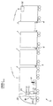
- a typical freight train 1 includes one or more locomotives 2, a plurality of railcars 3 and a pneumatic trainline known as the "brake pipe" 4.
- the brake pipe is the means by which brake commands are pneumatically conveyed from the lead locomotive 2 to each of the railcars 3 in the train.
- the brake pipe 4 is actually composed of a series of interconnected pipe lengths 4a, with one pipe length secured to the underside of each railcar.
- the pipe length 4a on each railcar is connected at each end to one end of an angle cock 5.
- Each angle cock 5 is connected at its other end to one end of a hose 6, with the other end of the hose being connected to a glad hand 7.
- glad hand coupler the pneumatic connection that links the pipe lengths of the adjacent railcars.
- the brake pipe 4 of the train is thus formed by coupling the glad hand 7 of each railcar to the glad hand of the railcar or locomotive located immediately adjacent to it. It is to the brake pipe 4 of the train that the pneumatic brake equipment on each railcar connects via a branch pipe 8. (Closing an angle cock 5 prevents air from flowing along the brake pipe to any of the railcars located downstream of the closed angle cock.)
- the locomotive 2 itself has its own pneumatic trainlines including a main reservoir equalizing (MRE) pipe, an independent application and release (IAR) pipe, and an actuating pipe.
- MRE main reservoir equalizing
- IAR independent application and release
- actuating pipe Within a locomotive consist (i.e., two or more locomotives connected together), the MRE, actuating and IAR pipes of each locomotive connect to the MRE, actuating and IAR pipes of adjacent locomotives.
- the locomotive houses the electronic air brake equipment, such as the EPIC ⁇ 3102 or EPIC ⁇ II type brake control systems produced by the Westinghouse Air Brake Company (WABCO). As shown in Figure 1, such equipment typically includes a cab station unit 20, a brake control computer 30, a pneumatic operating unit (POU) 40 and a locomotive interface unit (LIU) 45.
- POU pneumatic operating unit
- LIU locomotive interface unit
- POU pneumatic operating unit
- the cab station unit 20 houses the automatic and independent brake handles 21 and 22, and generates various signals including those representing the positions of the brake handles 21 and 22. These signals are conveyed to the brake control computer 30. Based on the inputs it receives and the software that dictates its operation, the brake control computer 30 controls the overall operation of the brakes. According to the commands it receives, including those from the brake control computer 30, the POU 40 affects the pressure in the IAR and brake pipes, as well as in the other pneumatic trainlines, and thereby controls the brakes on the train.
- the POU 40 features a pneumatic laminate to which the brake control computer 30 and various pneumatic and electropneumatic operating portions mount. Through a number of ports and internal passages, the pneumatic laminate interconnects these operating portions to each other and to branch pipes that carry air from or to the actuating pipe, the MRE pipe, the IAR pipe, the brake pipe, the brake cylinder and/or various storage tanks such as the equalizing reservoir in the locomotive.
- the various devices mounted to the pneumatic laminate are the independent application and release (IAR) portion, the brake cylinder (BC) control portion and the brake pipe (BP) control portion.
- IAR independent application and release
- BC brake cylinder
- BP brake pipe
- it is primarily the brake control computer 30, based on the inputs it receives and the software that dictates its operation, that controls the operation of these three operating portions of the POU 40.
- the pneumatic brake equipment on a typical freight railcar includes two storage reservoirs 9/10, one or more brake cylinders 11 and at least one brake control valve 12 such as an ADB, ABDX or ABDW type valve made by the Westinghouse Air Brake Company (WABCO).
- the brake control valve 12 has a service portion 13 and an emergency portion 14 typically mounted on a pipe bracket 15.
- the pipe bracket features a number of internal passages and several ports. Each port connects to one of the interconnecting pipes from the railcar such as those leading to the brake pipe, the brake cylinder and the two reservoirs. It is through the ports and internal passages of the pipe bracket 15 that the service and emergency portions 13 and 14 of the brake control valve 12 communicate fluidly with the pneumatic piping on the railcar.
- the automatic brake handle 21 can be moved from and in between a release position at one extreme in which brake pipe pressure is maximum and the brakes are completely released to an emergency position at another extreme in which brake pipe pressure is zero and the brakes are fully applied.
- the automatic brake handle positions include release, minimum service, full service, suppression, continuous service and emergency. Between the minimum and full service positions lies the service zone wherein each incremental movement of the automatic brake handle 21 toward the full service position causes the pressure within the brake pipe 4 to reduce incrementally.
- moving the automatic brake handle 21 By moving the automatic brake handle 21, the operator can control the pressure level in the brake pipe 4 and thereby direct whether, and to what extent, the brakes on both the locomotive(s) and the railcars are applied. More specifically, moving the automatic brake handle causes the brake control computer 30 to affect the operation of the BP control portion of the POU 40.
- the BP control portion affects the pressure within the equalization reservoir of the locomotive whose pressure the brake pipe 4 generally mimics.
- the pressure in the brake pipe 4 in turn, affects not only the operation of the brake control valve(s) 12 on each railcar 3 but also the operation of the BC control portion in the locomotive 2.
- the pressure level within the brake pipe 4 determines whether the brake control valve 12 on each railcar will charge its reservoirs 9/10 or deliver pressurized air previously stored in one or both of its reservoirs 9/10 to the brake cylinders 11.
- the brake pipe 4 is used to convey release, service and emergency brake commands to the pneumatic brake equipment on each railcar 3 in the train.
- the brake control computer 30 commands the BP control portion to increase pressure within the equalizing reservoir and thus the brake pipe 4.
- the MRE pipe in the locomotive is used to charge the brake pipe 4 to a normal maximum operating pressure via the BP control portion.
- the service portion 13 of each brake control valve 12 In response to this release brake command (i.e., when brake pipe pressure is restored to the maximum pressure set by the operator), the service portion 13 of each brake control valve 12 not only charges its two reservoirs 9/10 with the pressurized air it receives from the brake pipe 4 but also vents its brake cylinders 11 to atmosphere thereby causing the brakes on the railcar to release.
- the BC control portion in the locomotive also responds pneumatically to the increase in brake pipe pressure by venting air from the brake cylinders of the locomotive.
- Moving the automatic brake handle to its release position also causes the brake control computer to command electrically the solenoid valves of BC control portion to depressurize the locomotive brake cylinders.
- the BC control portion thus releases the locomotive brakes by responding both pneumatically to the increase in brake pipe pressure and electrically to electrical brake release commands issued by the brake control computer 30.
- the brake control computer 30 commands the BP control portion to reduce pressure within the equalizing reservoir and thus the brake pipe 4, though in a manner corresponding to handle position.
- this service brake command i.e., when brake pipe pressure is reduced at a service rate
- the service portion 13 of each brake control valve 12 supplies air from only one of its two reservoirs 9 to its brake cylinders 11 so as to apply the brakes on the railcar. How much the brake pipe pressure is reduced, and thus the magnitude of the service brake application, depends on how far the automatic brake handle 21 is moved towards the full service position.
- pressure transducers provide electrical signals indicative of the current pressures in the equalizing reservoir and brake pipe 4 to the brake control computer 30. Based in part on these signals, the brake control computer 30 then commands the BC control portion in the locomotive 2 to direct air from the main reservoir to the locomotive, brake cylinders to apply the brakes of the locomotive.
- the brake control computer 30 commands the BP control portion to reduce the pressure in the brake pipe 4 in the aforementioned manner.
- the brake equipment energizes two emergency magnet valves located in the BP control portion.
- One emergency magnet valve is energized by the brake control computer 30 whereas the other emergency magnet valve is energized directly by a microswitch that closes when the automatic brake handle 21 is moved into its emergency position.
- the BP control portion vents the brake pipe 4 to atmosphere at an emergency rate via its emergency vent valve.
- the service and emergency portions 13/14 of each brake control valve 12 supplies air from both reservoirs 9/10 to the brake cylinders 11 so as to apply the brakes of the railcar fully.
- the emergency portion 14 on each brake control valve 12 also serves to propagate the emergency brake command along the brake pipe 4 by rapidly venting its portion of the brake pipe 4a to atmosphere. This accelerates the pressurizing of the brake cylinders 11 on each railcar 3 and thereby reduces the distance that the train needs to stop.
- the BC control portion in the locomotive 2 also responds to this precipitous drop in brake pipe pressure by directing air from the main reservoir to the locomotive brake cylinders thereby quickly applying the brakes of the locomotive.
- the conductor's valve 23 also referred to as the helper's valve.
- the conductor's valve 23 By moving the handle of this valve to the open (i.e., emergency) position, the conductor's valve not only vents the brake pipe to atmosphere at an emergency rate but also allows air from the main reservoir of the locomotive to flow to, and thus close, an emergency pressure switch (EMPS).
- EMPS emergency pressure switch
- the EMPS provides battery voltage to one of the input relays of the LIU 45. It is through this EMPS input relay that the LIU signals the brake control computer 30 that the emergency was initiated by the train operator, or by another person located in the same compartment as the operator, rather than by the train breaking apart as described below.
- the independent brake handle 22 can be moved from and in between a release position at one extreme to a full apply position at the other extreme.
- the range encompassing a point just next to the release position up to and including the full apply position is referred to as the application zone.
- the brake control computer 30 responds by commanding the IAR control portion of the POU 40 to exhaust air from the IAR pipe.
- the BC control portion of the POU 40 responds pneumatically to this loss in IAR pipe pressure by venting air from the locomotive brake cylinders thereby releasing the locomotive brakes.
- the brake control computer 30 responds by commanding the IAR portion to raise the pressure in the IAR pipe.
- the BC control portion directs air to the locomotive brake cylinders thereby applying the locomotive brakes.
- the pressure in the IAR pipe and the locomotive brake cylinders thus reduces and increases in proportion to the position of the independent brake handle 22.
- the BC control portion also controls the pressure in the locomotive brake cylinders in response to pressure carried by the brake pipe as noted above. In a manner well known in the industry, the BC control portion can also control the pressure in the locomotive brake cylinders in response to the electrical commands generated by movement of the brake handles 21 and 22.
- actuation position also known as the bail off position.
- the independent brake handle 22 causes the brake control computer 30 to command the IAR control portion to charge the actuating pipe.
- the brake control computer 30 responds by commanding the BC control portion to release the pressure from the brake cylinders of the locomotive.
- the brake control computer 30 will continue to allow the pressure to drop as long as the handle 22 is held in the bail off position.
- the handle can be allowed to move (i.e., untilt) out of its bail off position at any time.
- the brake control computer 30 will command the BC control portion to keep the locomotive brake cylinders at whatever pressure they currently retain or to increase their pressure to the desired level. It is in this manner that the independent brake handle 22 can also be used to bail off the brakes of the locomotive(s) while the brakes of the railcars remain applied.
- each brake cylinder converts to mechanical force the pressurized air that it receives from its corresponding brake control valve. From the brake cylinder this force is transmitted by mechanical linkage (not shown) to the brake shoes (not shown) causing the brake shoes to be forced against, and thus to slow or stop the rotation of, the wheels of the rail vehicle.
- the magnitude of the braking force applied to the wheels is directly proportional to the pressure built up in the brake cylinders 11. Conveyed along the brake pipe 4 to the pneumatic brake equipment on each railcar 3, it is thus the pneumatic brake commands that determine whether, and to what extent, the brakes of the freight train 1 will be applied.
- a freight train 1 may also be equipped with a two-way end-of-train (EOT) radio telemetry system such as the TRAINLINK ® II EOT system designed and manufactured by WABCO.
- EOT end-of-train
- TRAINLINK ® II EOT system designed and manufactured by WABCO.
- two-way EOT systems typically feature a locomotive control unit (LCU) 51 in the lead locomotive 2 and an EOT unit 55 connected to the brake pipe typically on the last railcar in the train.
- LCU locomotive control unit
- HET head of train
- the LCU is mounted to the train operator's console in the locomotive 2.
- the EOT unit 55 transmits to the HOT unit 51 data pertaining to the pressure in the brake pipe and the motion of the last railcar.
- the EOT unit 55 includes a pressure transducer to monitor brake pipe pressure, a motion sensor to sense movement of the last railcar, a microprocessor unit to control the overall operation of these components and a transceiver (i.e., combination transmitter and receiver) that the microprocessor unit uses to transmit this last railcar data.
- the HOT unit 51 includes a primary display, a transceiver to receive transmissions from the EOT unit and a microprocessor unit. Controlled by this microprocessor unit, the HOT display is used to visually convey the last railcar data to the train operator.
- the HOT unit 51 will also display that an emergency condition exists at the rear of the train.
- the EOT unit is typically configured so that the emergency condition represents a sudden loss of brake pipe pressure or a drop in brake pipe pressure below a preset level.
- the emergency brake application starts at the locomotive and progresses along the brake pipe to the last railcar.
- NOTE An emergency application is initiated at a rate much faster than a service application.
- the maximum speed at which the reduction propagates could approach, theoretically, the speed of sound. It is normally slower than this, however, say in the range of 900 fps. Consequently, for a one mile long train, the propagation time would be more in the range of 10 to 15 seconds.
- the HOT unit 51 is equipped with an emergency toggle switch and the EOT unit 55 equipped with an emergency brake valve.
- the train operator can cause the HOT unit 51 to transmit a radio emergency brake signal to the EOT unit 55.
- the EOT unit responds to this emergency signal by commanding its emergency brake valve to reduce, at an emergency rate, the pressure in the brake pipe from the rear of the train.
- the two-way EOT system allows the railcar brakes to be applied more quickly in an emergency.
- the HOT unit 51 also has a supplemental display by which it visually conveys additional information to the train operator such as data related to arming of the EOT system and verification of communications between the HOT and EOT units.
- a freight train may be equipped with a more advanced EOT radio telemetry system, such as the TRAINLINK ® ES system.
- the TRAINLINK® ES system has a Service Interface Unit (SIU) 52 that connects between the serial port of the HOT unit and the brake pipe 4 on the locomotive 2.
- SIU keeps the microprocessor of the HOT unit constantly apprised of the pressure level within the brake pipe at the head of the train. This allows the HOT unit to automatically initiate a service brake application at the last railcar simultaneously with the service reduction in brake pipe pressure initiated from the locomotive.
- the HOT unit 51 in the locomotive automatically transmits a radio service brake signal to the EOT unit 55 when it detects a service reduction in brake pipe pressure via the SIU 52.
- the EOT unit 55 in this TRAINLINK ® ES type system responds to the service brake signal by commanding its brake valve to reduce the brake pipe pressure from the last railcar at the same service rate as that ordered by the locomotive brake equipment at the head of the train.
- a service application of the brakes can thus be made much faster on a train equipped with a TRAINLINK ® ES or similar type EOT system.
- the HOT unit 51 can also automatically transmit an emergency brake signal when an emergency reduction in brake pipe pressure has been initiated from the locomotive 2.
- the emergency toggle switch on the HOT unit 51 can also be used to manually transmit the emergency brake signal.
- the invention provides a method of coordinating the actions of a two-way end-of-train (EOT) system on a train with the brake equipment on a locomotive of the train during an emergency.
- EOT end-of-train
- the method includes the steps of: (1) monitoring the train for signs of an emergency by using the brake equipment of the locomotive; (2) determining, if an emergency has occurred, whether the emergency is due to disjoining of the train; (3) waiting a preset time period, if the emergency was caused by disjoining of the train, before causing the brake equipment of the locomotive, to command the two-way EOT system to initiate an emergency application of the brakes from a rear part of the train; and (4) waiting an alternative time period, if the emergency was caused other than by disjoining of the train, before causing the brake equipment of the locomotive to command the two-way EOT system to initiate the emergency application of the brakes from the rear part of the train.
- the method of the invention is described as if implemented in an EPIC ⁇ type brake control system and a TRAINLINK ® type EOT radio telemetry system.
- the invention primarily implicates the brake control computer 30 of the EPIC ⁇ brake control system and the HOT unit 51 of the TRAINLINK ⁇ EOT system.
- the invention can be carried out by making certain modifications to the hardware of both systems and by adding algorithms embodying the following method steps into the programming code of the brake control computer 30.
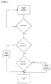
- Figure 3 illustrates the essential steps for a method of coordinating the actions of the brake control system in the locomotive with the two-way EOT system on the train.
- the steps of the method are basically as follows. First, using the brake equipment in the locomotive, the train is monitored for signs of an emergency. Second, if an emergency has occurred, it must be determined whether the emergency is due to disjoining of the train. Third, if the emergency was caused by a disjoining of the train, the method requires waiting a preset time period. Once the preset time has expired, the locomotive brake equipment is used to command the two-way EOT system to initiate an emergency application of the brakes from a rear part of the train.
- the method requires waiting an alternative time period. Once the alternative time period has expired, the locomotive equipment is used to command the two-way EOT system to initiate the emergency application of the brakes from the rear of the train.
- the brake control computer 30 of the EPIC ⁇ type brake control system can be used to monitor the brake equipment of the locomotive for most signs of an emergency. Many operating parameters can be taken into account in determining whether an emergency has occurred. The exact number and combination of input parameters will depend on the particular demands of the railroad operating authority for whom the invention is provided. Operating according to algorithms incorporated into its programming code, the brake control computer 30 can determine from the presence or absence of such inputs whether an emergency has indeed occurred and, if so, if it was caused by disjoining of the train. For example, the computer 30 can be used to monitor, essentially simultaneously, the automatic brake handle 21, the EMPS input relay of the LIU 45 and various other known components or subsystems of the locomotive brake equipment.
- Placement of the automatic brake handle 21 into the emergency position is, of course, an indication that the emergency was initiated by the train operator rather than by disjoining of the train.
- the battery signal supplied from the EMPS input relay of the LIU also indicates that the emergency was initiated by the train operator (or by another person located in the same compartment as the operator), but, in this case, from the conductor's valve 23.
- the brake control computer 30 uses certain transducers to monitor the pressure within various pneumatic trainlines and reservoirs on the locomotive.
- the brake pipe transducer provides a signal indicative of pressure within the brake pipe, and another transducer similarly monitors pressure within the equalization reservoir.
- the brake control computer 30 from one or more transducers receives signal(s) indicating that the brake pipe pressure is dropping at an emergency rate.
- the computer reads that (i) the automatic brake handle 21 has not been placed in the emergency position and (ii) no battery signal was received from the LIU EMPS input relay.
- the brake control computer 30 can determine from this particular combination of inputs that an emergency does indeed exist and that it was caused either by disjoining of the train or by another serious problem likewise manifested in a very high rate of leakage from the brake pipe.
- the brake control computer 30 reads that either (i) the automatic brake handle 21 has been placed in the emergency position or (ii) the battery signal was received from the EMPS input relay of the LIU 45, or both. From this particular set of inputs, the brake control computer 30 would determine that an emergency has occurred, but that it was initiated manually in the locomotive(s) by the train operator or another person located in the same compartment as the operator.
- the LIU 45 has a bank of output relays by which the brake control computer 30 can provide various output signals to other equipment in the locomotive.
- One of these output relays or a new relay altogether, hereinafter referred to as the HOT output relay could be wired into a new circuit containing the brake control computer 30 and the HOT unit 51.
- the HOT output relay could be wired so that its contacts are in parallel circuit relationship with the contacts of the emergency toggle switch in the HOT unit 51, and its coil energizable by the brake control computer 30. By energizing the coil and thereby closing the contacts of the HOT output relay, the brake control computer 30 can command the HOT unit 51 to transmit an emergency brake signal to the EOT unit 55 located at or near the rear of the train.
- the HOT unit would still be able to perform all of the functions previously attributed to it by the prior art. Specifically, the emergency toggle switch on the HOT unit 51 could still be used to manually transmit the emergency brake signal. Likewise, for a TRAINLINK® ES type EOT system, the HOT unit 51 would still be capable of automatically transmitting the emergency brake signal in response to an emergency reduction in brake pipe pressure detected by the SIU 52 in the locomotive 2. Regardless of how the HOT unit is commanded to transmit the emergency brake signal, the EOT unit 55 would, of course, still respond to this emergency brake signal by commanding its emergency brake valve to reduce, at an emergency rate, the pressure in the brake pipe at the rear of the train.
- the brake control computer 30 when it detects that the train has disjoined, the brake control computer 30 energizes the coil of the HOT output relay after the preset time period has expired.
- the preset time period is preferably set at zero seconds. Given this preferred zero-second delay, the brake control computer 30 would close the contacts of the HOT output relay as soon as it detects that the train has broken apart. The HOT unit 51 would then immediately respond to the closing of the contacts by transmitting the emergency brake signal. The goal of this third method step would then be achieved, that is, the EOT unit has been commanded to activate.
- the EOT unit 51 responds to the emergency brake signal by commanding its emergency brake valve to reduce, at an emergency rate, the brake pipe pressure from the rear of the train. Combined with the high rate of leakage from the brake pipe at the point at which the rear part separated, the extra reduction in pressure made by the EOT unit 55 allows the brakes of the rear part to be applied even more quickly during this emergency.
- the brake control computer 30 when it detects that the emergency has resulted from a cause other than the train breaking apart, the brake control computer 30 will not command the HOT unit 51 to transmit the emergency brake signal until the alternative time period has expired.
- the brake control computer 30 can be used to calculate how long this delay should last based on the operating parameters of the train. For example, if it is determined that the emergency was caused by the automatic brake handle 21 being placed into the emergency position, an alternative time period of seven (7) seconds could be imposed. Assuming such a delay, the emergency reduction in pressure initiated from the locomotive 2 has seven seconds to propagate along the brake pipe 4 towards the rear of the train before the brake control computer 30 commands the HOT unit 51 to transmit the emergency brake signal.
- the length of the preset and alternative time periods will depend on the specific braking equipment used by, and the operating philosophy of, the railroad operating authority for whom the invention is provided. For emergencies caused by disjoining of the train, a delay of zero seconds will probably be preferred. This further reduces the likelihood of a collision between the separated front and rear parts of the train.
- the brake control computer 30 is preferably programmed to select the time delay according to the specific type of emergency that occurred. Other factors may also be taken into account in determining the alternative time period, such as length and speed of the train, grade of the railway track on which the train is travelling, whether the independent brake handle 22 is in the bail off position, and the degree of tractive power provided by the locomotive. For freight trains, the alternative time period will typically be less than the preset time period and fall in the range of zero to ten seconds.
- this method can be embodied in various combinations of locomotive brake equipment and EOT radio telemetry systems.
- the method could be embodied in such combinations either alone or in conjunction with equipment provided by builders of train locomotives such as the Integrated Cab Electronics (ICE) system made by General Motors Corporation or the Integrated Function Control (IFC) system produced by General Electric Corporation.
- ICE Integrated Cab Electronics
- IFC Integrated Function Control
- the method could alternatively be implemented using the cab control computer of the cab station unit 20 (shown in Figure 1) along with the onboard computer of the ICE or IFC systems.
- the onboard computer is interfaced with many of the various subsystems on the train including, in some locomotives, the HOT unit 51 of the EOT radio telemetry system. Consequently, from the cab station unit 20 alone, or in combination with the brake control computer 30, a serial communications link can be had via the onboard computer to the HOT unit 51. Through this communications link, the HOT unit 51 could be commanded to transmit the emergency brake signal pursuant to the method presented in this document. This, of course, would eliminate the need for the aforementioned HOT output relay.
- the method allows the brakes to be applied during an emergency in a way which minimizes the buff and draft forces produced within the train. Reducing the force with which adjacent vehicles bump into each other (buff forces) means that damage is less likely to be suffered by the vehicles, the couplers that connect them and the cargo they carry. Reducing the force with which adjacent vehicles pull apart from each other (draft forces) means that the train is less likely to break apart and suffer damage to its couplers.
- the method presented herein enables the combined systems to apply the brakes, during an emergency, in a safer manner than would otherwise be possible using prior art methods.
Landscapes
- Engineering & Computer Science (AREA)
- Power Engineering (AREA)
- Transportation (AREA)
- Mechanical Engineering (AREA)
- Life Sciences & Earth Sciences (AREA)
- Sustainable Development (AREA)
- Sustainable Energy (AREA)
- Braking Systems And Boosters (AREA)
- Electric Propulsion And Braking For Vehicles (AREA)
Applications Claiming Priority (2)
| Application Number | Priority Date | Filing Date | Title |
|---|---|---|---|
| US09/158,489 US6195600B1 (en) | 1998-09-22 | 1998-09-22 | Method of controlling emergency brake applications by two-way end of train devices using existing electronic air brake equipment |
| US158489 | 1998-09-22 |
Publications (2)
| Publication Number | Publication Date |
|---|---|
| EP0989014A2 true EP0989014A2 (fr) | 2000-03-29 |
| EP0989014A3 EP0989014A3 (fr) | 2001-12-05 |
Family
ID=22568356
Family Applications (1)
| Application Number | Title | Priority Date | Filing Date |
|---|---|---|---|
| EP99117847A Withdrawn EP0989014A3 (fr) | 1998-09-22 | 1999-09-10 | Méthode de régulation d'application d'un frein de secour dans des dispositif de fin du train dans deux sens utilisant l'équipement éxistant d'un frein électronique à air comprimé |
Country Status (6)
| Country | Link |
|---|---|
| US (1) | US6195600B1 (fr) |
| EP (1) | EP0989014A3 (fr) |
| AU (1) | AU744759B2 (fr) |
| BR (1) | BR9917314A (fr) |
| CA (1) | CA2251316C (fr) |
| ZA (1) | ZA995777B (fr) |
Families Citing this family (14)
| Publication number | Priority date | Publication date | Assignee | Title |
|---|---|---|---|---|
| US6435623B1 (en) | 1997-10-10 | 2002-08-20 | Ge Harris Railway Electronics, Llc | Valve assembly for electrically controlled pneumatic brakes |
| US7096096B2 (en) * | 2003-07-02 | 2006-08-22 | Quantum Engineering Inc. | Method and system for automatically locating end of train devices |
| US20090043435A1 (en) * | 2007-08-07 | 2009-02-12 | Quantum Engineering, Inc. | Methods and systems for making a gps signal vital |
| US7872591B2 (en) * | 2007-10-30 | 2011-01-18 | Invensys Rail Corporation | Display of non-linked EOT units having an emergency status |
| US20100213321A1 (en) * | 2009-02-24 | 2010-08-26 | Quantum Engineering, Inc. | Method and systems for end of train force reporting |
| US8509970B2 (en) * | 2009-06-30 | 2013-08-13 | Invensys Rail Corporation | Vital speed profile to control a train moving along a track |
| US9026281B2 (en) * | 2010-08-23 | 2015-05-05 | Amstead Rail Company, Inc. | Railcar handbrake monitor |
| US9481348B2 (en) * | 2012-09-20 | 2016-11-01 | Wabtec Holding Corp. | System and method for addressing a pneumatic emergency in a helper locomotive |
| AU2013101329A4 (en) * | 2012-10-10 | 2013-10-31 | General Electric Company | Systems and methods for vehicle braking control |
| US8942868B2 (en) | 2012-12-31 | 2015-01-27 | Thales Canada Inc | Train end and train integrity circuit for train control system |
| US9701323B2 (en) | 2015-04-06 | 2017-07-11 | Bedloe Industries Llc | Railcar coupler |
| US12371077B2 (en) | 2018-01-24 | 2025-07-29 | Amsted Rail Company, Inc. | Sensing method, system and assembly for railway assets |
| EP3743899A4 (fr) | 2018-01-24 | 2021-10-27 | Amsted Rail Company, Inc. | Procédé, système et ensemble de détection de trappe de déchargement |
| EP4400384A3 (fr) | 2018-07-12 | 2024-12-04 | Amsted Rail Company, Inc. | Systèmes de surveillance de freinage pour véhicules ferroviaires |
Family Cites Families (5)
| Publication number | Priority date | Publication date | Assignee | Title |
|---|---|---|---|---|
| US5377938A (en) * | 1992-12-01 | 1995-01-03 | Pulse Electronics, Inc. | Railroad telemetry and control systems |
| US5383717A (en) * | 1993-09-10 | 1995-01-24 | Pulse Electronics | Brake control of helper locomotive |
| US5507457A (en) * | 1995-02-13 | 1996-04-16 | Pulse Electronics, Inc. | Train integrity detection system |
| US5681015A (en) * | 1996-12-20 | 1997-10-28 | Westinghouse Air Brake Company | Radio-based electro-pneumatic control communications system |
| US5813635A (en) * | 1997-02-13 | 1998-09-29 | Westinghouse Air Brake Company | Train separation detection |
-
1998
- 1998-09-22 US US09/158,489 patent/US6195600B1/en not_active Expired - Lifetime
- 1998-10-23 CA CA002251316A patent/CA2251316C/fr not_active Expired - Lifetime
-
1999
- 1999-09-08 ZA ZA9905777A patent/ZA995777B/xx unknown
- 1999-09-09 AU AU47494/99A patent/AU744759B2/en not_active Ceased
- 1999-09-10 EP EP99117847A patent/EP0989014A3/fr not_active Withdrawn
- 1999-09-20 BR BR9917314-0A patent/BR9917314A/pt unknown
Also Published As
| Publication number | Publication date |
|---|---|
| EP0989014A3 (fr) | 2001-12-05 |
| AU744759B2 (en) | 2002-03-07 |
| BR9917314A (pt) | 2002-06-25 |
| CA2251316C (fr) | 2003-03-11 |
| CA2251316A1 (fr) | 2000-03-22 |
| US6195600B1 (en) | 2001-02-27 |
| ZA995777B (en) | 2000-04-12 |
| AU4749499A (en) | 2000-03-23 |
Similar Documents
| Publication | Publication Date | Title |
|---|---|---|
| AU2017216469B2 (en) | Redundant method of confirming an ecp penalty | |
| US8406941B2 (en) | Adaptive brake scheme during a distributed power communication loss | |
| US6189980B1 (en) | Locomotive to ECP brake conversion system | |
| CA2320071C (fr) | Systeme de freinage de vehicules sur rails | |
| US5934764A (en) | Method for limiting brake cylinder pressure on locomotives equipped with distributive power and electronic brake systems | |
| JP2865652B2 (ja) | 空気列車指令線制御ユニット | |
| US6195600B1 (en) | Method of controlling emergency brake applications by two-way end of train devices using existing electronic air brake equipment | |
| CA2212105C (fr) | Unite de commande de double conduite generale pneumatique | |
| CA2203605C (fr) | Dispositif de detection de conduite generale | |
| JP2865650B2 (ja) | 汎用空気ブレーキ制御ユニット | |
| JPH10203347A (ja) | ブレーキ保証モジュール | |
| MXPA00007640A (es) | Valvula de ventilacion electronica. | |
| JP7634011B2 (ja) | 安全な追加ブレーキ機能を実行するためのブレーキシステム | |
| US20040104311A1 (en) | System to provide enhanced security and control of locomotives and trains | |
| MXPA99008698A (en) | Method for controlling emergency brake applications for bidirectional devices of train tail, using electronic equipment existing from air brakes comprim | |
| MXPA99011315A (es) | Sistema de conversion de freno ecp para locomotoras | |
| HK1031350A (en) | Locomotive to ecp brake conversion system | |
| MXPA98004309A (es) | Sistema electronico de frenos neumaticos |
Legal Events
| Date | Code | Title | Description |
|---|---|---|---|
| PUAI | Public reference made under article 153(3) epc to a published international application that has entered the european phase |
Free format text: ORIGINAL CODE: 0009012 |
|
| AK | Designated contracting states |
Kind code of ref document: A2 Designated state(s): AT BE CH CY DE DK ES FI FR GB GR IE IT LI LU MC NL PT SE |
|
| AX | Request for extension of the european patent |
Free format text: AL;LT;LV;MK;RO;SI |
|
| PUAL | Search report despatched |
Free format text: ORIGINAL CODE: 0009013 |
|
| AK | Designated contracting states |
Kind code of ref document: A3 Designated state(s): AT BE CH CY DE DK ES FI FR GB GR IE IT LI LU MC NL PT SE |
|
| AX | Request for extension of the european patent |
Free format text: AL;LT;LV;MK;RO;SI |
|
| AKX | Designation fees paid | ||
| REG | Reference to a national code |
Ref country code: DE Ref legal event code: 8566 |
|
| STAA | Information on the status of an ep patent application or granted ep patent |
Free format text: STATUS: THE APPLICATION IS DEEMED TO BE WITHDRAWN |
|
| 18D | Application deemed to be withdrawn |
Effective date: 20011001 |