EP0989032A2 - Module multi - capteurs pour communiquer des informations d'un capteur sur un bus de données de véhicule - Google Patents
Module multi - capteurs pour communiquer des informations d'un capteur sur un bus de données de véhicule Download PDFInfo
- Publication number
- EP0989032A2 EP0989032A2 EP99202562A EP99202562A EP0989032A2 EP 0989032 A2 EP0989032 A2 EP 0989032A2 EP 99202562 A EP99202562 A EP 99202562A EP 99202562 A EP99202562 A EP 99202562A EP 0989032 A2 EP0989032 A2 EP 0989032A2
- Authority
- EP
- European Patent Office
- Prior art keywords
- data bus
- vehicle data
- sensors
- sensor
- connector
- Prior art date
- Legal status (The legal status is an assumption and is not a legal conclusion. Google has not performed a legal analysis and makes no representation as to the accuracy of the status listed.)
- Withdrawn
Links
- 238000004891 communication Methods 0.000 claims abstract description 38
- 238000012545 processing Methods 0.000 claims abstract description 31
- 238000006243 chemical reaction Methods 0.000 claims description 3
- 238000000034 method Methods 0.000 description 10
- 239000000463 material Substances 0.000 description 6
- 230000001133 acceleration Effects 0.000 description 5
- 239000012530 fluid Substances 0.000 description 3
- 239000002184 metal Substances 0.000 description 3
- 229910052751 metal Inorganic materials 0.000 description 3
- 239000004033 plastic Substances 0.000 description 3
- 229920003023 plastic Polymers 0.000 description 3
- 230000008569 process Effects 0.000 description 3
- 239000004677 Nylon Substances 0.000 description 2
- 239000000919 ceramic Substances 0.000 description 2
- 239000004020 conductor Substances 0.000 description 2
- 239000011521 glass Substances 0.000 description 2
- 150000002739 metals Chemical class 0.000 description 2
- 238000012986 modification Methods 0.000 description 2
- 230000004048 modification Effects 0.000 description 2
- 229920001778 nylon Polymers 0.000 description 2
- 230000035755 proliferation Effects 0.000 description 2
- 230000005855 radiation Effects 0.000 description 2
- CBENFWSGALASAD-UHFFFAOYSA-N Ozone Chemical compound [O-][O+]=O CBENFWSGALASAD-UHFFFAOYSA-N 0.000 description 1
- 235000010627 Phaseolus vulgaris Nutrition 0.000 description 1
- 244000046052 Phaseolus vulgaris Species 0.000 description 1
- 239000004642 Polyimide Substances 0.000 description 1
- 239000000853 adhesive Substances 0.000 description 1
- 230000001070 adhesive effect Effects 0.000 description 1
- 229910045601 alloy Inorganic materials 0.000 description 1
- 239000000956 alloy Substances 0.000 description 1
- 230000004075 alteration Effects 0.000 description 1
- PNEYBMLMFCGWSK-UHFFFAOYSA-N aluminium oxide Inorganic materials [O-2].[O-2].[O-2].[Al+3].[Al+3] PNEYBMLMFCGWSK-UHFFFAOYSA-N 0.000 description 1
- 238000005267 amalgamation Methods 0.000 description 1
- 229910010293 ceramic material Inorganic materials 0.000 description 1
- 238000002485 combustion reaction Methods 0.000 description 1
- 239000002131 composite material Substances 0.000 description 1
- 230000003247 decreasing effect Effects 0.000 description 1
- 238000013461 design Methods 0.000 description 1
- 238000001514 detection method Methods 0.000 description 1
- 239000011152 fibreglass Substances 0.000 description 1
- -1 for example Inorganic materials 0.000 description 1
- 230000006870 function Effects 0.000 description 1
- 230000005484 gravity Effects 0.000 description 1
- 238000012544 monitoring process Methods 0.000 description 1
- 229920001721 polyimide Polymers 0.000 description 1
- 229920000642 polymer Polymers 0.000 description 1
- 230000001737 promoting effect Effects 0.000 description 1
- 230000009467 reduction Effects 0.000 description 1
- 239000012858 resilient material Substances 0.000 description 1
- 229910000679 solder Inorganic materials 0.000 description 1
- 230000000153 supplemental effect Effects 0.000 description 1
Images

Classifications
-
- B—PERFORMING OPERATIONS; TRANSPORTING
- B60—VEHICLES IN GENERAL
- B60R—VEHICLES, VEHICLE FITTINGS, OR VEHICLE PARTS, NOT OTHERWISE PROVIDED FOR
- B60R16/00—Electric or fluid circuits specially adapted for vehicles and not otherwise provided for; Arrangement of elements of electric or fluid circuits specially adapted for vehicles and not otherwise provided for
- B60R16/02—Electric or fluid circuits specially adapted for vehicles and not otherwise provided for; Arrangement of elements of electric or fluid circuits specially adapted for vehicles and not otherwise provided for electric constitutive elements
- B60R16/03—Electric or fluid circuits specially adapted for vehicles and not otherwise provided for; Arrangement of elements of electric or fluid circuits specially adapted for vehicles and not otherwise provided for electric constitutive elements for supply of electrical power to vehicle subsystems or for
- B60R16/0315—Electric or fluid circuits specially adapted for vehicles and not otherwise provided for; Arrangement of elements of electric or fluid circuits specially adapted for vehicles and not otherwise provided for electric constitutive elements for supply of electrical power to vehicle subsystems or for using multiplexing techniques
Definitions
- the present invention relates generally to systems for communicating sensor information to a vehicle control computer, and more specifically to such systems for communicating sensor information over a vehicle data bus.
- Automotive control systems typically include a number of engine and/or vehicle operating condition sensors and sensing systems which provide corresponding sensor signals to a control computer.
- the control computer which may be an engine/vehicle control computer or other control computer associated with an automotive control module, is in turn responsive to the sensor signals to control an associated automotive component.
- the number of required sensors may be small and/or a sufficient number of control computer inputs may be readily available so that the sensors may be wired directly to corresponding inputs of the control computer.
- An example of one such system is illustrated in U.S. Patent NO. 5,392,024 to Kiuchi et al.
- the number of automotive sensors or sensing systems have increased and/or the number of available control computer inputs have decreased, and a need to accommodate such a disparity has thus arisen.
- multi-sensor module for communicating sensor information over a vehicle data bus comprises a plurality of sensors producing a plurality of sensor signals indicative of a corresponding plurality of vehicle operating conditions, a first signal processing circuit receiving the plurality of sensor signals and producing a time-division muliplexed signal representative of the plurality of sensor signals according to a first vehicle data bus communications protocol, and a housing having the plurality of sensors and the first signal processing circuit mounted therein.
- a multi-sensor module is connected to a vehicle control computer via a vehicle data bus, wherein the multi-sensor module comprises a plurality of sensors producing a plurality of sensor signals indicative of a corresponding plurality of vehicle operating conditions, a signal processing circuit receiving the plurality of sensor signals and producing at an output thereof a time-division muliplexed signal representative of the plurality of sensor signals according to a vehicle data bus communications protocol, a housing having the plurality of sensors and the signal processing circuit mounted therein, and a connector mounted to the housing, wherein the connector defines one end connected to the output of the signal processing circuit and an opposite end connected to the vehicle data bus.
- One object of the present invention is to provide a sensor module configured for mounting multiple sensors therein and equipped with communications circuitry capable of broadcasting on a vehicle data bus information corresponding to sensor signals produced by each of the sensors mounted within the module.
- Another object of the present invention is to provide such a module capable of broadcasting sensor information on the vehicle data bus in accordance with any known vehicle data bus communications protocol.
- Yet another object of the present invention is to provide such a module that is sufficiently flexible in design to permit a wide variety of sensors to be mounted within the module, and to further permit broadcasting of the sensor information according to a number of different vehicle data bus communication protocols.
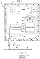
- Module 10 includes a housing 12 having a number of sensors S 1 - S N and signal processing circuitry mounted therein.
- Housing 12 may or may not be a completely closed container as will be more fully described hereinafter, and may be positioned at various locations within or on the vehicle wherein the particular location of housing 12 will typically be dictated by the type of sensors S 1 - S N mounted therein. Accordingly, housing 12 may be formed of various materials including known metals, ceramics, plastics and other polymers, nylon, glass and the like, as well as any combination thereof.
- housing 12 The particular material or materials used to form housing 12 will typically be dictated by the environment in which the housing 12 will be located and/or the type of sensors mounted therein.
- collision sensors typically require rigid attachment thereof to an underlying structure, and a correspondingly rigid material, such as any of a variety of known metals, alloys, composites and/or amalgamations thereof, may be used to form housing 12.
- underhood applications typically require resilience to temperature extremes, moisture, corrosive elements and the like, and may therefore accordingly require housing 12 to be formed of a correspondingly resilient material such as ceramic, nylon, some known plastics, and/or the like.
- circuit board 14 is mounted within housing 12, preferably in accordance with one or more known techniques, wherein circuit board 14 may be formed of a known and typical circuit board material or materials.
- circuit board 14 may be a so-called surface mount circuit board which is often formed of a ceramic material such as, for example, alumina, and wherein circuit interconnections are defined thereon.
- board 14 may be a so-called printed circuit board formed of, for example, rigid glass and/or fiberglass layers with thin metal interconnection strips printed thereon.
- board 14 may be a so-called flex-circuit formed of, for example, a flexible film of plastic, polyimide, or the like.
- circuit board 14 may be any known circuit board type or structure, wherein the particular type or structure will typically dictate a number of possible known techniques for mounting the board 14 within the housing 12 (i.e. adhesive, solder, mechanical attachment, etc.). It should also be understood that although only one circuit board 14 is illustrated in FIG. 1, the present invention contemplates that more than one circuit board may be mounted within housing 12, and that such multiple circuit boards may be further mounted to each other in accordance with known techniques.
- sensors S 1 - S N are mounted within housing 12, wherein sensors S 1 - S N may be any known sensors or sensing systems operable to sense operating conditions associated with an internal combustion engine or with a vehicle carrying the engine, and produce sensor signals corresponding thereto.
- sensors S 1 - S N may be of the same type (e.g. motion sensors) or may be a combination of different sensor types, and those skilled in the art will recognize that any particular combination of known sensors or sensing systems fall within the scope of the present invention.
- sensors S 1 - S N are mounted to circuit board 14 in accordance with known sensor mounting techniques, as illustrated in FIG.
- circuit paths 22 1 and 22 N form part of circuit board 14 as is known in the art, although the present invention contemplates that circuit paths 22 1 and 22 N may be formed of a combination of circuit board interconnections and discrete conductors such as in the case that one or more of the sensors S 1 - S N are mounted to a structure within housing 12 that is separate or remote from circuit board 14.
- Multiplexing circuit 20 is connected to a known controller circuit 26 via signal path 28, and controller circuit 26 is connected to a known transceiver circuit 30 via number of signal paths 32 1 - 32 M .
- multiplexing circuit 20, controller 26 and transceiver circuit 30 are each formed of an independent integrated circuit that is mounted to circuit board 14 in accordance with known techniques.
- any combination (or all) of circuits 20, 26 and 30 may be formed of a single integrated circuit.
- the multiplexing circuit 20 and controller circuit 26 may be combined to form a single integrated multiplexer/controller circuit 34.
- the controller circuit 26 is designed to operate strictly as a preprogrammed controller circuit, as will be described more fully hereinafter.
- controller circuit 26 includes a microprocessor portion and a memory unit, whereby the microprocessor portion may be used to accomplish a number of functions including sensor calibrations.
- transceiver circuit 30 is electrically connected to one end of an electrical connector 36 via signal path 38, wherein the opposite end of connector 36 is electrically connected to a vehicle data bus 18.
- Connector 36 is preferably mounted or attached to housing 12.
- the vehicle data bus 18 is also connected to an input/output port I/O of a control computer 16, wherein control computer 16 may be an engine control computer, vehicle control computer and/or any other auxiliary computer operable to control and manage a vehicle operating condition.
- Vehicle data bus 18, as this term is used herein, may be any generic vehicle data bus or may alternatively be a predetermined vehicle data bus or "datalink" structure having a predefined bus architecture.
- Vehicle data bus 18 may accordingly be a one, two, three or more wire conductor having either a generic architecture or a predefined bus architecture such as that defined by, for example, ISO 11519, ISO 11898, SAE J1850, SAE J1708, SAE J1939, or IEEE 1394.
- module 10 may include a second electrical connector 40, preferably mounted or attached to housing 12, and having signal paths 42 and 44 connected therefrom to circuit board 14.
- the opposite end of connector 40 is electrically connected to a vehicle power and ground bus 46 that typically includes at least a pair of wires carrying a dc potential and a ground potential respectively.
- the dc, typically 5-12 volts, and ground potentials are thus supplied to circuit board 14 via signal paths 42 and 44.
- multiplexing circuit 20, controller circuit 26 and transceiver circuit 30 form signal processing circuitry which, in accordance with the present invention, is operable to time-division multiplex the sensor signals provided by sensors S 1 - S N and broadcast the time-division multiplexed sensor signal on the vehicle data bus 18 according to a predetermined vehicle data bus communications protocol. More specifically, sensors S 1 - S N are operable to produce sensor signals indicative of corresponding vehicle operating conditions, wherein each of the various sensor signals are provided to multiplexing circuit 20 via signal paths 22 1 - 22 N .
- Multiplexing circuit 20 is operable, as is known in the art, to time-division multiplex the sensor signals on signal paths 22 1 - 22 N and provide a corresponding time-division multiplexed sensor signal on signal path 28.
- Controller circuitry 26 is preferably preprogrammed in accordance with a predetermined vehicle data bus communications protocol to process the time-division multiplexed sensor signal and produce the time-division multiplexed sensor signal according to the predetermined vehicle data bus communications protocol on signal paths 32 1 - 32 M , wherein M may be any integer.
- the transceiver circuitry 30 is, in turn, operable to broadcast the time-division multiplexed sensor signal, according to the predetermined vehicle data bus protocol, on signal path 38 and, via connector 36, on vehicle data bus 18.
- Control computer 16 may thus access the sensor signals produced by sensors S 1 - S N by monitoring the I/O port and receiving the time-division multiplexed sensor signal broadcast on the vehicle data bus 18 by module 10 according to the predefined vehicle data bus communications protocol.
- the controller circuitry 26 may be programmed to process the time-division multiplexed sensor signal and produce this signal according to any of a variety of desired vehicle data bus communications protocols.
- controller circuitry 26 may include a microprocessor portion and a memory unit that has information stored therein relating to conversion of sensor data to the desired vehicle data bus communications protocol.
- the microprocessor portion of the controller circuitry 26 is operable to process the time-division multiplexed sensor signal according to instructions stored in the memory unit and produce the time-division multiplexed sensor signal according to the desired vehicle data bus communications protocol.
- controller circuitry 26 may be programmed to convert the time-division multiplexed sensor signal to any of a variety of known vehicle data bus communication protocols including, but not limited to, CLASS 2, CAN, GMLAN, UART, PALMNET, ABUS, MI-BUS, I2C, Safety Bus, CCD, BEAN or the like.
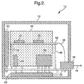
- FIG. 2 a side-elevational and cross-sectional view of another preferred embodiment of a multi-sensor module 10', in accordance with the present invention, is shown.
- module 10' is an example of one specific application of the generic module 10 shown and described with respect to FIG. 1, wherein module 10' includes a number of vehicle motion and impact sensors.
- housing 12 may be a completely enclosed container that is preferably rigid and mountable at or near a center of gravity of the vehicle.
- circuit board 14 of FIG. 1 is, in the embodiment illustrated in FIG. 2, replaced with a pair of circuit boards 50 and 52.
- Circuit board 50 is preferably mounted within housing 12 and further has connector 36 as well as all impact and motion sensors mounted thereto.
- circuit board 50 includes attached thereto a first known high-G acceleration sensing circuit 58, a second known high-G acceleration sensing circuit 60 disposed 90 degrees relative to sensing circuit 58, a first known angular rate and low-G acceleration sensing circuit 62, a second known angular rate and low-G acceleration sensing circuit 64 disposed 90 degrees relative to sensing circuit 62 and a third known angular rate and low-G acceleration sensing circuit 66 disposed 90 degrees relative to both sensing circuits 62 and 64.
- Circuit board 52 has the signal processing circuitry, represented as circuits 30 and 34, mounted thereto, wherein signal path 38 extends from circuit board 52 to connector 36 and is electrically connected to vehicle data bus 18.
- Circuit board 52 is preferably connected to structurally and electrically to circuit board 50 via connection paths 54 and 56 such that signal paths from each of the sensors 58-66 extend therealong to multiplexer/controller circuit 34.
- Module 10' thus provides a self-contained vehicle motion and impact sensing system that provides for two axes of impact detection (sensors 58 and 60) and three axes of motion, i.e. pitch (sensor 62), roll (sensor 64) and yaw (sensor 66), wherein a time-division multiplexed combination of signals produced by these sensors is broadcast by signal processing circuitry 30 and 34 onto a vehicle data bus according to a desired vehicle data bus communications protocol.
- FIG. 3 a side-elevational and cross-sectional view of yet another alternative embodiment of a multi-sensor module 10'', in accordance with the present invention, is shown.
- Module 10'' is included to illustrate how the multi-sensor module concept of the present invention is sufficiently flexible to allow a number of different types of sensors to be combined within a single housing, and wherein signals relating to each of the sensors are broadcast by circuitry contained within the module 10'' onto a vehicle data bus 18 according to a desired vehicle data bus communications protocol.
- housing 12' includes a number of windows and/or ports and is therefore not a completely enclosed container. However, each of the various windows and/or ports are preferably sealed by mounting an appropriate sensor thereto so that the interior of housing 12' is isolated from the outside during use.
- module 10'' includes a pair of circuit boards 70 and 72, wherein circuit board 70 is mounted within housing 12' and has multiplexer/controller circuit 34, transceiver circuit 30 and connector 36 mounted thereto.
- Circuit board 72 has a number of sensors electrically connected thereto wherein the sensors, in this embodiment, are mechanically attached to housing 12' rather than to the circuit board 72 as shown in the previously discussed embodiments. In any case, circuit board 72 is mounted to circuit board 70 via connection paths 74 and 76 such that signal paths extend therealong from each of the sensors to multiplexer/controller circuit 34.
- module 10'' is a gas sensor 86 operable to sample a gas such as, for example, CO, NOx, humidity, ozone, or the like, and provide a corresponding gas level signal to circuit 34 via signal path 88.
- module 10'' preferably includes a passageway 78 extending therethrough having an inlet port 80 receiving the gas and an outlet port 82 from which gas flow continues.
- Passageway 78 preferably defines an opening 84 therein through which sensor 86 extends so as to position a gas sensing portion of sensor 78 in contact with the gas flowing through passageway 78.
- passageway 78 sealingly engages housing 12' adjacent to the gas inlet port 80 and the gas outlet port 82 so that the interior of housing 12' is isolated from the ambient area surrounding housing 12'.
- sensor 84 preferably sealingly engages opening 84 to thereby isolate the interior of housing 12' from the gas flowing through passageway 78.
- a temperature sensor 92 operable to sense temperature of the ambient area surrounding module 10'' and provide a corresponding temperature signal to circuit 34 via signal path 94.
- Housing 12' preferably defines an opening 90 therein through which temperature sensor 92 extends so as to position a temperature sensing portion of sensor 92 in contact with the ambient area surrounding module 10''.
- sensor 92 sealingly engages opening 90 of housing 12' to thereby isolate the interior of housing 12' from the ambient area surrounding housing 12'.
- a pressure sensor 98 operable to sense the pressure of a fluid or vacuum within passageway 100 that is affixed to housing 12', and provide a corresponding pressure signal to circuit 34 via signal path 102.
- Housing 12' preferably defines an opening 96 through which a pressure sensor 98 extends so as to position a pressure sensing portion of sensor 98 into contact with the fluid for which pressure or vacuum is to be determined.
- passageway 100 sealingly engages housing 12' adjacent to opening so that the actual pressure within passageway 100 is not corrupted by the ambient area surrounding housing 12'.
- sensor 98 preferably sealingly engages opening 96 to thereby isolate the interior of housing 12' from the fluid flowing through passageway 78.
- Still another one of the sensors included in the module 10'' is a light sensor 108 operable to sense light intensity of the area surrounding housing 12'and provide a corresponding light signal to circuit 34 via signal path 110.
- Housing 12' preferably defines an opening 104 through which light sensor 108 extends so as to position a light sensing portion of sensor 108 into within view of the ambient area surrounding module 10''.
- a light transmissive window 106 is positioned within opening 104 and sealingly engages opening 104 so that the interior of housing 12' is isolated from the ambient area surrounding module 10''.
- window 106 may be omitted in which case sensor 108 preferably sealingly engages opening 104 to thereby isolate the interior of housing 12' from the ambient area surrounding module 10''.
- sensor 108 may alternatively be used to sense an intensity of other light sources such as, for example, sunlight, IR radiation or other light sources, via proper placement of module 10'' proximate to the appropriate radiation source and/or via attachment of a light-directing passageway, similar to passageways 78 or 100, proximate to opening 104.
- other light sources such as, for example, sunlight, IR radiation or other light sources
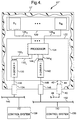
- FIG. 4 a top plan and partial cutaway view of another preferred embodiment of a multi-sensor module 10''', in accordance with the present invention, is shown.
- Module 10''' is similar in many respects to module 10 illustrated in FIG. 1 in that a housing 12'' includes a number of sensors S 1 - S N and signal processing circuitry mounted therein, wherein the signal processing circuitry is operable to broadcast onto at least one vehicle data bus a time-division multiplexed signal corresponding to the various sensor signals in accordance with a predefined vehicle data bus communications protocol.
- sensors S 1 - S N are mounted to a circuit board 120 which is itself preferably mounted within housing 12''.
- one or more of the sensors S 1 - S N may be mechanically mounted to another structure within housing 12'' or to housing 12'' itself with each of the sensors being electrically connected to circuit board 120.
- Sensors S 1 - S N are electrically connected to a processor 124 via a corresponding number of signal paths 126 1 - 126 N , wherein processor 124 is mounted to a second circuit board 122.
- Processor 124 may be a combination multiplexer/controller as described hereinabove with respect to FIG. 1 or may further include a microprocessor portion and a memory unit also as described hereinabove.
- processor 124 is electrically connected to a first transceiver 130 via a number of signal paths 132 1 - 132 L , wherein L may be any integer.
- Transceiver 130 is preferably mounted to circuit board 122 and is electrically connected via signal path 136 to a first connector 134 that is preferably attached to housing 12''.
- Connector 134 is electrically connected to a first vehicle data bus 140 which is also connected to an input/output port I/O of a first control system 138, wherein control system 138 includes a control computer as described hereinabove with respect to FIG. 1.
- Processor 124 is also electrically connected to a second transceiver 142 via number of signal paths 144 1 - 144 K , wherein K may be any integer.
- Transceiver 142 is preferably mounted to circuit board 122 and is electrically connected via signal path 148 to a second connector 146 that is preferably attached to housing 12''.
- Connector 146 is electrically connected to a second vehicle data bus 152 which is also connected to an input/output port I/O of a second control system 150, wherein control system 150 includes a control computer as described hereinabove with respect to FIG. 1.
- Module 10''' may further include a power and ground bus connection thereto (40-46) identical to that described with respect to FIG. 1, or may alternatively receive power via one of the vehicle data buses 140 or 152. In either case, module 10'''' is similar in operation to module 10 described with respect to FIG. 1 except that module 10''' is capable of broadcasting time-division multiplexed sensor signals on vehicle data buses 140 and 152 according to different vehicle data bus communication protocols.
- processor 124 is preferably configured, according to one or more techniques described hereinabove, to translate the time-division multiplexed sensor signal to two separate vehicle data bus communication protocols.
- module 10''' is operable to broadcast the time-division multiplexed sensor signal to a number of vehicle control systems wherein the various vehicle control systems communicate over a dedicated vehicle data bus having a unique communications protocol.
- the first vehicle control system 138 may be a computer-controlled supplemental inflatable restraint system wherein the vehicle data bus architecture requires communication via a CAN protocol
- the second vehicle control system may be an engine control system wherein the vehicle data bus architecture requires communication via an SAE J1850 protocol.
Landscapes
- Engineering & Computer Science (AREA)
- Mechanical Engineering (AREA)
- Small-Scale Networks (AREA)
- Selective Calling Equipment (AREA)
- Arrangements For Transmission Of Measured Signals (AREA)
Applications Claiming Priority (2)
| Application Number | Priority Date | Filing Date | Title |
|---|---|---|---|
| US09/146,896 US6338010B1 (en) | 1998-09-03 | 1998-09-03 | Multi-sensor module for communicating sensor information over a vehicle data bus |
| US146896 | 1998-09-03 |
Publications (2)
| Publication Number | Publication Date |
|---|---|
| EP0989032A2 true EP0989032A2 (fr) | 2000-03-29 |
| EP0989032A3 EP0989032A3 (fr) | 2001-04-04 |
Family
ID=22519466
Family Applications (1)
| Application Number | Title | Priority Date | Filing Date |
|---|---|---|---|
| EP99202562A Withdrawn EP0989032A3 (fr) | 1998-09-03 | 1999-08-04 | Module multi - capteurs pour communiquer des informations d'un capteur sur un bus de données de véhicule |
Country Status (2)
| Country | Link |
|---|---|
| US (1) | US6338010B1 (fr) |
| EP (1) | EP0989032A3 (fr) |
Cited By (8)
| Publication number | Priority date | Publication date | Assignee | Title |
|---|---|---|---|---|
| DE10056549A1 (de) * | 2000-11-15 | 2002-06-06 | Bosch Gmbh Robert | Mehrfachnutzung von Sensorsignalen durch mehrere Fahrzeugsysteme |
| DE10064934A1 (de) * | 2000-12-23 | 2002-06-27 | Bayerische Motoren Werke Ag | Standardinterface für Fahrzeuge |
| WO2003099616A1 (fr) * | 2002-05-25 | 2003-12-04 | Robert Bosch Gmbh | Calculateur electronique embarque dans un vehicule et capteur |
| DE102005023862A1 (de) * | 2005-05-24 | 2006-11-30 | Valeo Schalter Und Sensoren Gmbh | Spurerkennungssystem und Betriebsverfahren hierfür |
| WO2007061595A2 (fr) | 2005-11-23 | 2007-05-31 | Autoliv Asp, Inc. | Systeme de reseau de capteur distant avec redondance |
| DE102011009267A1 (de) * | 2011-01-24 | 2012-07-26 | Valeo Schalter Und Sensoren Gmbh | Sensoranordnung für ein Kraftfahrzeug, Kraftfahrzeug und Verfahren zur Herstellung einer Sensoranordnung |
| WO2013083398A1 (fr) * | 2011-12-08 | 2013-06-13 | Bayerische Motoren Werke Aktiengesellschaft | Installation de communication pour un vehicule a moteur |
| DE102019124794A1 (de) * | 2019-09-16 | 2021-03-18 | Bayerische Motoren Werke Aktiengesellschaft | Verfahren, Vorrichtung, Computerprogramm und computerlesbares Speichermedium zur Verarbeitung von Messsignalen |
Families Citing this family (55)
| Publication number | Priority date | Publication date | Assignee | Title |
|---|---|---|---|---|
| US7580782B2 (en) * | 1995-10-30 | 2009-08-25 | Automotive Technologies International, Inc. | Vehicular electronic system with crash sensors and occupant protection systems |
| EP1149006B1 (fr) * | 1999-02-01 | 2013-03-13 | Continental Teves AG & Co. oHG | Procede et dispositif de surveillance de detecteurs, en particulier pour un systeme esp pour vehicules |
| US6909944B2 (en) * | 1999-07-30 | 2005-06-21 | Oshkosh Truck Corporation | Vehicle control system and method |
| US6553290B1 (en) * | 2000-02-09 | 2003-04-22 | Oshkosh Truck Corporation | Equipment service vehicle having on-board diagnostic system |
| US20030158635A1 (en) * | 1999-07-30 | 2003-08-21 | Oshkosh Truck Corporation | Firefighting vehicle with network-assisted scene management |
| US7024296B2 (en) * | 1999-07-30 | 2006-04-04 | Oshkosh Truck Corporation | Control system and method for an equipment service vehicle |
| US7107129B2 (en) | 2002-02-28 | 2006-09-12 | Oshkosh Truck Corporation | Turret positioning system and method for a fire fighting vehicle |
| US20040133319A1 (en) * | 1999-07-30 | 2004-07-08 | Oshkosh Truck Corporation | User interface and method for vehicle control system |
| US7184866B2 (en) | 1999-07-30 | 2007-02-27 | Oshkosh Truck Corporation | Equipment service vehicle with remote monitoring |
| US6922615B2 (en) * | 1999-07-30 | 2005-07-26 | Oshkosh Truck Corporation | Turret envelope control system and method for a fire fighting vehicle |
| US6882917B2 (en) * | 1999-07-30 | 2005-04-19 | Oshkosh Truck Corporation | Steering control system and method |
| US7729831B2 (en) | 1999-07-30 | 2010-06-01 | Oshkosh Corporation | Concrete placement vehicle control system and method |
| US6993421B2 (en) * | 1999-07-30 | 2006-01-31 | Oshkosh Truck Corporation | Equipment service vehicle with network-assisted vehicle service and repair |
| US7006902B2 (en) * | 1999-07-30 | 2006-02-28 | Oshkosh Truck Corporation | Control system and method for an equipment service vehicle |
| US6885920B2 (en) * | 1999-07-30 | 2005-04-26 | Oshkosh Truck Corporation | Control system and method for electric vehicle |
| US7127331B2 (en) | 1999-07-30 | 2006-10-24 | Oshkosh Truck Corporation | Turret operator interface system and method for a fire fighting vehicle |
| US7184862B2 (en) * | 1999-07-30 | 2007-02-27 | Oshkosh Truck Corporation | Turret targeting system and method for a fire fighting vehicle |
| US7162332B2 (en) | 1999-07-30 | 2007-01-09 | Oshkosh Truck Corporation | Turret deployment system and method for a fire fighting vehicle |
| US7072745B2 (en) | 1999-07-30 | 2006-07-04 | Oshkosh Truck Corporation | Refuse vehicle control system and method |
| US7152133B2 (en) * | 2000-08-30 | 2006-12-19 | Dearborn Group, Inc. | Expanded functionality protocol adapter for in-vehicle networks |
| US20070124528A1 (en) * | 2000-08-30 | 2007-05-31 | Dearborn Group, Inc. | Expanded protocol adapter for in-vehicle networks |
| DE10044934B4 (de) * | 2000-09-12 | 2007-08-30 | Robert Bosch Gmbh | Vorrichtung zur Steuerung und/oder Regelung der Betriebsabläufe bei einem Kraftfahrzeug |
| US20020184348A1 (en) * | 2000-09-20 | 2002-12-05 | Lockheed Martin Corporation | Object oriented framework architecture for sensing and/or control environments |
| AU2001292819A1 (en) * | 2000-09-20 | 2002-04-02 | Lockheed Martin Corporation | Object oriented framework architecture for sensing and/or control environments |
| DE10048780A1 (de) * | 2000-09-29 | 2002-04-18 | Bosch Gmbh Robert | Verfahren und Vorrichtung zur Steuerung von Betriebsabläufen, insbesondere bei einem Fahrzeug |
| US7277782B2 (en) * | 2001-01-31 | 2007-10-02 | Oshkosh Truck Corporation | Control system and method for electric vehicle |
| US7379797B2 (en) * | 2001-01-31 | 2008-05-27 | Oshkosh Truck Corporation | System and method for braking in an electric vehicle |
| US20050113996A1 (en) * | 2001-12-21 | 2005-05-26 | Oshkosh Truck Corporation | Ambulance control system and method |
| US7302320B2 (en) * | 2001-12-21 | 2007-11-27 | Oshkosh Truck Corporation | Failure mode operation for an electric vehicle |
| US7254468B2 (en) * | 2001-12-21 | 2007-08-07 | Oshkosh Truck Corporation | Multi-network control system for a vehicle |
| US7792618B2 (en) | 2001-12-21 | 2010-09-07 | Oshkosh Corporation | Control system and method for a concrete vehicle |
| US6859696B2 (en) * | 2001-12-27 | 2005-02-22 | Caterpillar Inc | System and method for monitoring machine status |
| US7412307B2 (en) * | 2002-08-02 | 2008-08-12 | Oshkosh Truck Corporation | Refuse vehicle control system and method |
| DE10237160A1 (de) * | 2002-08-14 | 2004-02-26 | Robert Bosch Gmbh | Vorrichtung zur Aufprallsensierung mit wenigstens zwei Drucksensoren |
| US7493140B2 (en) * | 2003-01-22 | 2009-02-17 | Johnson Controls Technology Company | System, method and device for providing communication between a vehicle and a plurality of wireless devices having different communication standards |
| JP4139261B2 (ja) * | 2003-04-09 | 2008-08-27 | 矢崎総業株式会社 | フロント電装システム、フロント電装システム用電子制御ユニット及び電装コネクタ |
| US6917890B2 (en) * | 2003-05-29 | 2005-07-12 | Delphi Technologies, Inc. | Method to provide off-line transfer of vehicle calibration data |
| DE10331964B4 (de) * | 2003-07-15 | 2016-05-04 | Robert Bosch Gmbh | Vorrichtung zur Seitenaufprallerkennung und Drucksensor |
| US20090212978A1 (en) * | 2003-11-03 | 2009-08-27 | B & G Technologies, Inc. | System for managing a fleet of automotive vehicles |
| US20080133432A1 (en) * | 2003-11-03 | 2008-06-05 | Robert Ramseyer | Automated rental vehicle check-in system |
| US20110093160A1 (en) * | 2009-10-19 | 2011-04-21 | B&G Technologies, Llc | Vehicle check in method |
| US20080015908A1 (en) * | 2003-11-03 | 2008-01-17 | B&G Technologies, Llc | Automated vehicle check-in system |
| US20060280202A1 (en) * | 2005-06-13 | 2006-12-14 | Analog Devices, Inc. | MEMS sensor with configuration module |
| US20070088479A1 (en) * | 2005-10-19 | 2007-04-19 | Trw Automotive U.S. Llc | Apparatus with sensor assembly for sensing a vehicle crash condition and associated method |
| FR2896894B1 (fr) * | 2006-01-27 | 2008-12-05 | Valeo Systemes Thermiques | Systeme et procede de communication par bus de communication serie |
| US8139109B2 (en) | 2006-06-19 | 2012-03-20 | Oshkosh Corporation | Vision system for an autonomous vehicle |
| US8947531B2 (en) | 2006-06-19 | 2015-02-03 | Oshkosh Corporation | Vehicle diagnostics based on information communicated between vehicles |
| US9136708B2 (en) * | 2011-01-19 | 2015-09-15 | Alliance For Sustainable Energy, Llc | Simultaneous distribution of AC and DC power |
| US20150006037A1 (en) * | 2013-06-27 | 2015-01-01 | Ford Global Technologies, Llc | Integrated sensing system for parking aid and pedestrian impact detection |
| US9845191B2 (en) | 2013-08-02 | 2017-12-19 | Oshkosh Corporation | Ejector track for refuse vehicle |
| US20170210389A1 (en) * | 2016-01-22 | 2017-07-27 | Gkn Driveline North America, Inc. | Vehicle sensing system with at least two sensors |
| DE102017101545B4 (de) * | 2017-01-26 | 2025-01-30 | Infineon Technologies Ag | Sensorsteuereinheit, Sensorsignalempfänger, ein Modul mit inkrementellem, magnetischem Geschwindigkeitssensor, ein Verfahren für eine Sensorsteuereinheit, ein Verfahren für einen Sensorsignalempfänger und Computerprogramm |
| US10831206B2 (en) * | 2017-11-08 | 2020-11-10 | Tesla, Inc. | Autonomous driving system emergency signaling |
| US11022511B2 (en) | 2018-04-18 | 2021-06-01 | Aron Kain | Sensor commonality platform using multi-discipline adaptable sensors for customizable applications |
| CN114328356B (zh) * | 2022-01-04 | 2024-01-30 | 上海雨冉实业有限公司 | Gmlan信号与双线can信号的相互转换模块板 |
Citations (3)
| Publication number | Priority date | Publication date | Assignee | Title |
|---|---|---|---|---|
| US5392024A (en) | 1991-06-14 | 1995-02-21 | Toyota Jidosha Kabushiki Kaisha | Collision detection system |
| US5512890A (en) | 1992-02-19 | 1996-04-30 | Namco Controls Corporation | Sensor connection system |
| US5808689A (en) | 1994-04-20 | 1998-09-15 | Shoot The Moon Products, Inc. | Method and apparatus for nesting secondary signals within a television signal |
Family Cites Families (11)
| Publication number | Priority date | Publication date | Assignee | Title |
|---|---|---|---|---|
| US3866166A (en) * | 1974-04-09 | 1975-02-11 | Gen Motors Corp | Digital multigage for motor vehicle |
| DE3170955D1 (en) | 1980-12-17 | 1985-07-18 | Ici Plc | Apparatus for gathering data from a plurality of condition responsive optical sensors |
| US4736367A (en) | 1986-12-22 | 1988-04-05 | Chrysler Motors Corporation | Smart control and sensor devices single wire bus multiplex system |
| DE3809886C2 (de) | 1988-03-24 | 1997-01-16 | Teves Gmbh Alfred | Sensor für Kraftfahrzeuge |
| US5136998A (en) | 1990-02-06 | 1992-08-11 | Motorola, Inc. | Automotive control unit with internal sensor |
| DE4392671C2 (de) | 1992-06-10 | 2000-06-21 | Ford Werke Ag | Kommunikationssystem für Kraftfahrzeuge |
| US5469150A (en) | 1992-12-18 | 1995-11-21 | Honeywell Inc. | Sensor actuator bus system |
| US5613398A (en) | 1994-01-24 | 1997-03-25 | Chrysler Corporation | Smart fuel tank module |
| DE4427254B4 (de) | 1994-07-30 | 2004-02-26 | Kiekert Ag | Verschlußsystem für ein Kraftfahrzeug |
| GB9512929D0 (en) | 1995-06-24 | 1995-08-30 | Sun Electric Uk Ltd | Multi-gas sensor systems for automatic emissions measurement |
| EP0757442A3 (fr) | 1995-07-31 | 1998-12-30 | Delco Electronics Corporation | Module de circuit d'attaque pour bobine d'allumage |
-
1998
- 1998-09-03 US US09/146,896 patent/US6338010B1/en not_active Expired - Lifetime
-
1999
- 1999-08-04 EP EP99202562A patent/EP0989032A3/fr not_active Withdrawn
Patent Citations (3)
| Publication number | Priority date | Publication date | Assignee | Title |
|---|---|---|---|---|
| US5392024A (en) | 1991-06-14 | 1995-02-21 | Toyota Jidosha Kabushiki Kaisha | Collision detection system |
| US5512890A (en) | 1992-02-19 | 1996-04-30 | Namco Controls Corporation | Sensor connection system |
| US5808689A (en) | 1994-04-20 | 1998-09-15 | Shoot The Moon Products, Inc. | Method and apparatus for nesting secondary signals within a television signal |
Cited By (14)
| Publication number | Priority date | Publication date | Assignee | Title |
|---|---|---|---|---|
| DE10056549A1 (de) * | 2000-11-15 | 2002-06-06 | Bosch Gmbh Robert | Mehrfachnutzung von Sensorsignalen durch mehrere Fahrzeugsysteme |
| DE10056549C2 (de) * | 2000-11-15 | 2003-11-06 | Bosch Gmbh Robert | Mehrfachnutzung von Sensorsignalen durch mehrere Fahrzeugsysteme |
| DE10064934A1 (de) * | 2000-12-23 | 2002-06-27 | Bayerische Motoren Werke Ag | Standardinterface für Fahrzeuge |
| WO2003099616A1 (fr) * | 2002-05-25 | 2003-12-04 | Robert Bosch Gmbh | Calculateur electronique embarque dans un vehicule et capteur |
| DE102005023862A1 (de) * | 2005-05-24 | 2006-11-30 | Valeo Schalter Und Sensoren Gmbh | Spurerkennungssystem und Betriebsverfahren hierfür |
| WO2007061595A3 (fr) * | 2005-11-23 | 2007-07-12 | Autoliv Asp Inc | Systeme de reseau de capteur distant avec redondance |
| WO2007061595A2 (fr) | 2005-11-23 | 2007-05-31 | Autoliv Asp, Inc. | Systeme de reseau de capteur distant avec redondance |
| US7443310B2 (en) | 2005-11-23 | 2008-10-28 | Autoliv Asp, Inc. | Remote sensor network system with redundancy |
| DE102011009267A1 (de) * | 2011-01-24 | 2012-07-26 | Valeo Schalter Und Sensoren Gmbh | Sensoranordnung für ein Kraftfahrzeug, Kraftfahrzeug und Verfahren zur Herstellung einer Sensoranordnung |
| WO2013083398A1 (fr) * | 2011-12-08 | 2013-06-13 | Bayerische Motoren Werke Aktiengesellschaft | Installation de communication pour un vehicule a moteur |
| CN103974854A (zh) * | 2011-12-08 | 2014-08-06 | 宝马股份公司 | 用于机动车的通信装置 |
| CN103974854B (zh) * | 2011-12-08 | 2015-11-25 | 宝马股份公司 | 用于机动车的通信装置 |
| US9400494B2 (en) | 2011-12-08 | 2016-07-26 | Bayerische Motoren Werke Aktiengesellschaft | Communication device for a motor vehicle |
| DE102019124794A1 (de) * | 2019-09-16 | 2021-03-18 | Bayerische Motoren Werke Aktiengesellschaft | Verfahren, Vorrichtung, Computerprogramm und computerlesbares Speichermedium zur Verarbeitung von Messsignalen |
Also Published As
| Publication number | Publication date |
|---|---|
| US6338010B1 (en) | 2002-01-08 |
| EP0989032A3 (fr) | 2001-04-04 |
Similar Documents
| Publication | Publication Date | Title |
|---|---|---|
| US6338010B1 (en) | Multi-sensor module for communicating sensor information over a vehicle data bus | |
| US6441510B1 (en) | Reconfigurable modular instrument cluster arrangement | |
| US7331212B2 (en) | Sensor module | |
| US10773724B2 (en) | Accessory system for vehicle | |
| US20090134985A1 (en) | Modular sensor unit for a motor vehicle | |
| US20060038108A1 (en) | Image-generation device, in particular for installation in the roof area or exterior rearview mirror of a motor vehicle | |
| EP2060886A1 (fr) | Capteur combiné | |
| WO2002056940A3 (fr) | Système de cathéter détecteur et procédé de fabrication | |
| US6705671B1 (en) | Electronically integrated vehicle support structure | |
| WO2000071388A8 (fr) | Systeme de cablage electrique pour l'unite d'entrainement dans des vehicules | |
| US6511342B1 (en) | Modular instrument panel system having a flat flexible bus | |
| GB2307750A (en) | Control device having a pressure sensor | |
| US6817643B2 (en) | Vehicle console assembly | |
| KR20160098250A (ko) | 압력 센서 장치, 공기 유량 측정 장치, 공기 유량 측정 시스템 및 압력 측정 방법 | |
| US6181563B1 (en) | Meter device for vehicle | |
| AU6981900A (en) | System and method for carrying out an electronic control or regulation | |
| EP1054313B1 (fr) | Capteur de température | |
| US6062876A (en) | Electrical connection box for an automotive vehicle | |
| JP4118709B2 (ja) | コンビネーションスイッチモジュール | |
| US20040114335A1 (en) | Printed board and meter unit provided therewith | |
| Sparks et al. | Multi-sensor modules with data bus communication capability | |
| US6807060B2 (en) | Underhood electronic integration | |
| US6906613B1 (en) | Keyless entry system | |
| JPH0697684A (ja) | 電子回路装置 | |
| JPH06153270A (ja) | 電子回路装置 |
Legal Events
| Date | Code | Title | Description |
|---|---|---|---|
| PUAI | Public reference made under article 153(3) epc to a published international application that has entered the european phase |
Free format text: ORIGINAL CODE: 0009012 |
|
| AK | Designated contracting states |
Kind code of ref document: A2 Designated state(s): DE FR GB |
|
| AX | Request for extension of the european patent |
Free format text: AL;LT;LV;MK;RO;SI |
|
| PUAL | Search report despatched |
Free format text: ORIGINAL CODE: 0009013 |
|
| AK | Designated contracting states |
Kind code of ref document: A3 Designated state(s): AT BE CH CY DE DK ES FI FR GB GR IE IT LI LU MC NL PT SE |
|
| AX | Request for extension of the european patent |
Free format text: AL;LT;LV;MK;RO;SI |
|
| 17P | Request for examination filed |
Effective date: 20011004 |
|
| AKX | Designation fees paid |
Free format text: DE FR GB |
|
| 17Q | First examination report despatched |
Effective date: 20030314 |
|
| STAA | Information on the status of an ep patent application or granted ep patent |
Free format text: STATUS: THE APPLICATION IS DEEMED TO BE WITHDRAWN |
|
| 18D | Application deemed to be withdrawn |
Effective date: 20030925 |