EP0989041A2 - Dispositif pour appliquer une tension de ressort à une pince de câble - Google Patents
Dispositif pour appliquer une tension de ressort à une pince de câble Download PDFInfo
- Publication number
- EP0989041A2 EP0989041A2 EP99890117A EP99890117A EP0989041A2 EP 0989041 A2 EP0989041 A2 EP 0989041A2 EP 99890117 A EP99890117 A EP 99890117A EP 99890117 A EP99890117 A EP 99890117A EP 0989041 A2 EP0989041 A2 EP 0989041A2
- Authority
- EP
- European Patent Office
- Prior art keywords
- external thread
- pipe socket
- section
- housing
- screwed
- Prior art date
- Legal status (The legal status is an assumption and is not a legal conclusion. Google has not performed a legal analysis and makes no representation as to the accuracy of the status listed.)
- Granted
Links
- 230000008878 coupling Effects 0.000 claims abstract description 3
- 238000010168 coupling process Methods 0.000 claims abstract description 3
- 238000005859 coupling reaction Methods 0.000 claims abstract description 3
- 238000005452 bending Methods 0.000 description 3
Images
Classifications
-
- B—PERFORMING OPERATIONS; TRANSPORTING
- B61—RAILWAYS
- B61B—RAILWAY SYSTEMS; EQUIPMENT THEREFOR NOT OTHERWISE PROVIDED FOR
- B61B12/00—Component parts, details or accessories not provided for in groups B61B7/00 - B61B11/00
- B61B12/12—Cable grippers; Haulage clips
- B61B12/122—Cable grippers; Haulage clips for aerial ropeways
Definitions
- the subject invention relates to a device for application a spring tension on one with a rigid jaw and with a movable jaw designed clamping body for coupling of a hanger on a traction or conveyor rope, consisting of a pot-like housing in which spring elements, in particular disc springs, are arranged and with a protruding from this housing Pipe socket, which with a first external thread in a with a Internal thread trained bore of the sprag is screwed and which between the housing and the first external thread a second external thread is formed, on which a lock nut is screwable.
- the clamping bodies of known rope clips are with a longitudinal bore formed in which the actuating plunger for the movable Jaw is guided. This hole is provided with an internal thread, into which the actuator is screwed.
- Acquaintances with Actuators designed actuators consist of a pot-like Housing in which a set of disc springs is arranged. Of this housing protrudes with a pipe socket formed with an external thread which is screwed into the clamping body. From the disc springs another plunger goes off, which passes through the pipe socket and which interacts with the plunger located in the clamping body. Furthermore, the pipe socket is also outside of the sprag an external thread on which there is a lock nut, which can be screwed to the clamping body.
- this known actuating device therefore does not correspond to technical requirements, since the pipe socket protrudes from the housing in the area which is outside the clamping body and located outside the locknut, high changing bending loads exposed, making it very fragile in this area.
- the object of the invention is therefore based on the task to improve such device so that this the known State of the art disadvantage is avoided.
- this will achieved according to the invention in that the wall thickness of the second Screw-threaded section of the pipe socket at least 1.2 times the amount of the wall thickness of the screwed into the clamping body Has section of the pipe socket.
- the wall thickness preferably has that with the second external thread Provided section of the pipe socket about twice the amount Wall thickness of the section provided with the first external thread of the pipe socket. Furthermore, the length of the section is preferred with the second external thread about 0.5 times to 0.8 times the length of the section with the first external thread.
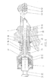
- FIG. 1 shows a rope clamp with a tensioning device according to the invention.
- the cable clamp 1 shown in Fig. 1 consists of a clamping body 11, which with a rigid jaw 12 and one opposite Clamping body 11 displaceable jaw 13 is formed. Means this jaws 12 and 13 is the cable clamp 1 to a train or Conveyor rope 10 of a drag lift system can be clamped.
- the clamp body 11 is formed with a longitudinal bore 14 in which a plunger 15 is guided is, the right end cooperates with the movable jaw 13. At its end facing away from the jaws 12 and 13 is the bore 14 of the clamping body 11 with an internal thread 16 educated.
- a hanger 20 is attached to the clamping body 1.
- the clamping body 1 is assigned an actuating device 2, which a Has pot-shaped housing 21, in which there are disc springs 22. From the housing 21 protrudes a raw connector 23, which on its Housing 21 remote end formed with an external thread 26 is, whereby the adjusting device 2 in the internal thread 16 of the clamping body 11 can be screwed in. Inside the pipe section 23 is another Tappet 25 is provided, which is located in its housing 21 End is formed with a disc 24 to which the set of disc springs 22 comes to rest and its other end face on the plunger 15 is present. By the plate springs 22 is on the plunger 25 and Ram 15 on the movable jaw 13 the required force applied to attach the cable clamp 1 to the cable 10.
- the pipe socket 23 projecting from the housing 21 is divided into two areas, which with the external thread 26 and with a further external thread 27 are formed.
- the section at the free end with the first external thread 26 has an external diameter, which corresponds to the inner diameter of the bore 14.
- the section located outside the clamping body 11 with the external thread 27 formed with a much larger diameter, wherein the wall thickness of this second section of the pipe socket 23 approximately is twice the wall thickness of the first section.
- a lock nut 28 is screwed on. By the lock nut 28 are on the pipe socket 23 in the area of the lock nut 28 so high tensile forces exerted that the acting on them changing bending forces can not cause breaks of the same.
- the pipe socket 23 is therefore not at risk of breakage, because he has a wall thickness approximately twice that of the one Section which is screwed into the clamping body 11.
- the housing 21 is also formed with a hexagon 29 through which it is rotatable relative to the clamping body 11. Through the Rotational position of the housing 21 relative to the clamping body 11 is the Tension of the plate springs 22 or thereby the clamping force of the cable clamp 1 set.
- a tension bolt 29 is firmly connected to the plunger 25, which penetrates the plate springs 22, which lie on the pipe socket 23 Side protrudes from the housing 21 and at its free end a pull plate 30 is arranged. If the cable clamp 1 is loosened is the tension bolt 29 by means of a hydraulic press tool adjusted against the action of the plate springs 22, which on the movable jaw 13 clamping force is lifted. This can the cable clamp 1 can be adjusted along the traction cable 10 without this complex assembly work is required.
Landscapes
- Engineering & Computer Science (AREA)
- Transportation (AREA)
- Mechanical Engineering (AREA)
- Flexible Shafts (AREA)
- Clamps And Clips (AREA)
- Wire Bonding (AREA)
- Lift-Guide Devices, And Elevator Ropes And Cables (AREA)
- Bridges Or Land Bridges (AREA)
- Ropes Or Cables (AREA)
Priority Applications (1)
| Application Number | Priority Date | Filing Date | Title |
|---|---|---|---|
| AT99890117T ATE252008T1 (de) | 1998-09-29 | 1999-04-08 | Einrichtung zur aufbringung einer federspannung auf eine seilklemme |
Applications Claiming Priority (2)
| Application Number | Priority Date | Filing Date | Title |
|---|---|---|---|
| AT161398 | 1998-09-29 | ||
| AT0161398A AT408539B (de) | 1998-09-29 | 1998-09-29 | Einrichtung zur aufbringung einer federspannung auf eine seilklemme |
Publications (3)
| Publication Number | Publication Date |
|---|---|
| EP0989041A2 true EP0989041A2 (fr) | 2000-03-29 |
| EP0989041A3 EP0989041A3 (fr) | 2000-11-08 |
| EP0989041B1 EP0989041B1 (fr) | 2003-10-15 |
Family
ID=3517218
Family Applications (1)
| Application Number | Title | Priority Date | Filing Date |
|---|---|---|---|
| EP99890117A Expired - Lifetime EP0989041B1 (fr) | 1998-09-29 | 1999-04-08 | Dispositif pour appliquer une tension de ressort à une pince de câble |
Country Status (4)
| Country | Link |
|---|---|
| EP (1) | EP0989041B1 (fr) |
| AT (2) | AT408539B (fr) |
| DE (1) | DE59907358D1 (fr) |
| NO (1) | NO320198B1 (fr) |
Cited By (1)
| Publication number | Priority date | Publication date | Assignee | Title |
|---|---|---|---|---|
| CN103909936A (zh) * | 2014-03-12 | 2014-07-09 | 山东科兴机电设备有限公司 | 深槽活动式抱索器 |
Families Citing this family (2)
| Publication number | Priority date | Publication date | Assignee | Title |
|---|---|---|---|---|
| CN104002821B (zh) * | 2014-03-12 | 2016-04-20 | 山东科兴机电设备有限公司 | 深槽固定式抱索器 |
| CN103978981B (zh) * | 2014-03-12 | 2016-06-01 | 山东科兴机电设备有限公司 | 深槽可摘挂式抱索器 |
Family Cites Families (5)
| Publication number | Priority date | Publication date | Assignee | Title |
|---|---|---|---|---|
| CH429811A (de) * | 1965-05-20 | 1967-02-15 | Brueder Girak Spezialfabrik Fu | Seilklemme |
| FR2127440A5 (fr) * | 1971-02-26 | 1972-10-13 | Pomagalski Sa | |
| US4031830A (en) * | 1975-06-14 | 1977-06-28 | Pohlig-Heckel-Bleichert Vereinigte Maschinenfabriken Aktiengesellschaft | Safety clamping device for pull-cable in aerial cableway arrangement |
| DE3523676A1 (de) * | 1985-07-03 | 1987-01-08 | Roehrs Werner Dr Kg | Seilklemmenversetzgeraet |
| FR2689847B1 (fr) * | 1992-04-10 | 1994-07-01 | Pomagalski Sa | Pince de telesiege. |
-
1998
- 1998-09-29 AT AT0161398A patent/AT408539B/de not_active IP Right Cessation
-
1999
- 1999-04-08 AT AT99890117T patent/ATE252008T1/de active
- 1999-04-08 DE DE59907358T patent/DE59907358D1/de not_active Expired - Lifetime
- 1999-04-08 EP EP99890117A patent/EP0989041B1/fr not_active Expired - Lifetime
- 1999-05-11 NO NO19992285A patent/NO320198B1/no not_active IP Right Cessation
Non-Patent Citations (1)
| Title |
|---|
| None |
Cited By (2)
| Publication number | Priority date | Publication date | Assignee | Title |
|---|---|---|---|---|
| CN103909936A (zh) * | 2014-03-12 | 2014-07-09 | 山东科兴机电设备有限公司 | 深槽活动式抱索器 |
| CN103909936B (zh) * | 2014-03-12 | 2016-08-17 | 山东科兴机电设备有限公司 | 深槽活动式抱索器 |
Also Published As
| Publication number | Publication date |
|---|---|
| DE59907358D1 (de) | 2003-11-20 |
| EP0989041B1 (fr) | 2003-10-15 |
| NO992285L (no) | 2000-03-30 |
| ATE252008T1 (de) | 2003-11-15 |
| NO320198B1 (no) | 2005-11-14 |
| EP0989041A3 (fr) | 2000-11-08 |
| AT408539B (de) | 2001-12-27 |
| ATA161398A (de) | 2001-05-15 |
| NO992285D0 (no) | 1999-05-11 |
Similar Documents
| Publication | Publication Date | Title |
|---|---|---|
| WO2007014647A1 (fr) | Dispositif de pression d'un systeme de serrage | |
| DE2504680B2 (de) | Abspannklemme für Freileitungen | |
| DE69733241T2 (de) | Riemenvorspannung eines Synchronisierungs- und Positionierungssystems einer Aufzugskabinentür | |
| EP4138238A1 (fr) | Aide au tirage de câbles | |
| AT408539B (de) | Einrichtung zur aufbringung einer federspannung auf eine seilklemme | |
| EP0406530A1 (fr) | Dispositif de serrage avec levier à genouillère pour la construction en carrosserie | |
| CH637561A5 (de) | Mechanische einspannvorrichtung fuer proben auf pruefmaschinen. | |
| DE19622390A1 (de) | Crimppresse mit Kraftsensor | |
| DE10156261C1 (de) | Greif- oder Spannvorrichtung | |
| DE2611168C3 (de) | Steckverbindung für zwei optische Bauelemente | |
| DE3017205C2 (de) | Verkokungsofentür | |
| DE3329171C2 (fr) | ||
| DE19635865A1 (de) | Spannkraft-Verstärker | |
| DE2927448C2 (de) | Einrichtung zum axialen Dehnen von Schraubenbolzen | |
| EP0611623B1 (fr) | Dispositif de fixation | |
| DE102006058653A1 (de) | Antrieb für eine Schiebetür | |
| DE20200370U1 (de) | Gelenkstativ | |
| DE10258454B4 (de) | Schelle | |
| DE2224040C3 (de) | Vorrichtung zum Einspannen eines scheibenförmigen Halbleiterbauelementes | |
| DE10031610A1 (de) | Kettenspanner | |
| DE102007059169A1 (de) | Vorrichtung zur statischen Positionierug von Einrichtungen | |
| DE2319388A1 (de) | Schraubenpresse | |
| DE19812623B4 (de) | Gelenkstativ | |
| WO2023247636A1 (fr) | Bague de presse, collier de presse et outil de pressage à élément de réglage | |
| AT398741B (de) | Bremsbetätigungsvorrichtung mit veränderlicher übersetzung |
Legal Events
| Date | Code | Title | Description |
|---|---|---|---|
| PUAI | Public reference made under article 153(3) epc to a published international application that has entered the european phase |
Free format text: ORIGINAL CODE: 0009012 |
|
| AK | Designated contracting states |
Kind code of ref document: A2 Designated state(s): AT CH DE FI IT LI SE |
|
| AX | Request for extension of the european patent |
Free format text: AL;LT;LV;MK;RO;SI |
|
| RAP1 | Party data changed (applicant data changed or rights of an application transferred) |
Owner name: INNOVA PATENT GMBH |
|
| PUAL | Search report despatched |
Free format text: ORIGINAL CODE: 0009013 |
|
| AK | Designated contracting states |
Kind code of ref document: A3 Designated state(s): AT BE CH CY DE DK ES FI FR GB GR IE IT LI LU MC NL PT SE |
|
| AX | Request for extension of the european patent |
Free format text: AL;LT;LV;MK;RO;SI |
|
| 17P | Request for examination filed |
Effective date: 20001221 |
|
| AKX | Designation fees paid |
Free format text: AT CH DE FI IT LI SE |
|
| 17Q | First examination report despatched |
Effective date: 20020829 |
|
| GRAH | Despatch of communication of intention to grant a patent |
Free format text: ORIGINAL CODE: EPIDOS IGRA |
|
| GRAS | Grant fee paid |
Free format text: ORIGINAL CODE: EPIDOSNIGR3 |
|
| GRAA | (expected) grant |
Free format text: ORIGINAL CODE: 0009210 |
|
| AK | Designated contracting states |
Kind code of ref document: B1 Designated state(s): AT CH DE FI IT LI SE |
|
| REG | Reference to a national code |
Ref country code: CH Ref legal event code: EP |
|
| REG | Reference to a national code |
Ref country code: SE Ref legal event code: TRGR |
|
| REG | Reference to a national code |
Ref country code: CH Ref legal event code: NV Representative=s name: LEMAN CONSULTING S.A. |
|
| REF | Corresponds to: |
Ref document number: 59907358 Country of ref document: DE Date of ref document: 20031120 Kind code of ref document: P |
|
| PLBE | No opposition filed within time limit |
Free format text: ORIGINAL CODE: 0009261 |
|
| STAA | Information on the status of an ep patent application or granted ep patent |
Free format text: STATUS: NO OPPOSITION FILED WITHIN TIME LIMIT |
|
| 26N | No opposition filed |
Effective date: 20040716 |
|
| PG25 | Lapsed in a contracting state [announced via postgrant information from national office to epo] |
Ref country code: IT Free format text: LAPSE BECAUSE OF NON-PAYMENT OF DUE FEES;WARNING: LAPSES OF ITALIAN PATENTS WITH EFFECTIVE DATE BEFORE 2007 MAY HAVE OCCURRED AT ANY TIME BEFORE 2007. THE CORRECT EFFECTIVE DATE MAY BE DIFFERENT FROM THE ONE RECORDED. Effective date: 20050408 |
|
| PGFP | Annual fee paid to national office [announced via postgrant information from national office to epo] |
Ref country code: AT Payment date: 20160428 Year of fee payment: 18 |
|
| PGFP | Annual fee paid to national office [announced via postgrant information from national office to epo] |
Ref country code: DE Payment date: 20170419 Year of fee payment: 19 Ref country code: CH Payment date: 20170419 Year of fee payment: 19 |
|
| PGFP | Annual fee paid to national office [announced via postgrant information from national office to epo] |
Ref country code: SE Payment date: 20170419 Year of fee payment: 19 Ref country code: FI Payment date: 20170412 Year of fee payment: 19 |
|
| REG | Reference to a national code |
Ref country code: AT Ref legal event code: MM01 Ref document number: 252008 Country of ref document: AT Kind code of ref document: T Effective date: 20170408 |
|
| PG25 | Lapsed in a contracting state [announced via postgrant information from national office to epo] |
Ref country code: AT Free format text: LAPSE BECAUSE OF NON-PAYMENT OF DUE FEES Effective date: 20170408 |
|
| REG | Reference to a national code |
Ref country code: DE Ref legal event code: R119 Ref document number: 59907358 Country of ref document: DE |
|
| REG | Reference to a national code |
Ref country code: CH Ref legal event code: PL |
|
| REG | Reference to a national code |
Ref country code: SE Ref legal event code: EUG |
|
| PG25 | Lapsed in a contracting state [announced via postgrant information from national office to epo] |
Ref country code: SE Free format text: LAPSE BECAUSE OF NON-PAYMENT OF DUE FEES Effective date: 20180409 Ref country code: FI Free format text: LAPSE BECAUSE OF NON-PAYMENT OF DUE FEES Effective date: 20180408 Ref country code: DE Free format text: LAPSE BECAUSE OF NON-PAYMENT OF DUE FEES Effective date: 20181101 |
|
| PG25 | Lapsed in a contracting state [announced via postgrant information from national office to epo] |
Ref country code: CH Free format text: LAPSE BECAUSE OF NON-PAYMENT OF DUE FEES Effective date: 20180430 Ref country code: LI Free format text: LAPSE BECAUSE OF NON-PAYMENT OF DUE FEES Effective date: 20180430 |