EP0989267A2 - Dispositif de verrouillage et porte avec un tel dispositif - Google Patents
Dispositif de verrouillage et porte avec un tel dispositif Download PDFInfo
- Publication number
- EP0989267A2 EP0989267A2 EP99118616A EP99118616A EP0989267A2 EP 0989267 A2 EP0989267 A2 EP 0989267A2 EP 99118616 A EP99118616 A EP 99118616A EP 99118616 A EP99118616 A EP 99118616A EP 0989267 A2 EP0989267 A2 EP 0989267A2
- Authority
- EP
- European Patent Office
- Prior art keywords
- lock
- locking
- locks
- door leaf
- actuating
- Prior art date
- Legal status (The legal status is an assumption and is not a legal conclusion. Google has not performed a legal analysis and makes no representation as to the accuracy of the status listed.)
- Withdrawn
Links
- 230000008878 coupling Effects 0.000 claims description 23
- 238000010168 coupling process Methods 0.000 claims description 23
- 238000005859 coupling reaction Methods 0.000 claims description 23
- 230000033001 locomotion Effects 0.000 claims description 15
- 230000005540 biological transmission Effects 0.000 claims description 9
- 238000003780 insertion Methods 0.000 claims description 3
- 230000037431 insertion Effects 0.000 claims description 3
- 230000007246 mechanism Effects 0.000 abstract description 9
- 238000012986 modification Methods 0.000 description 7
- 230000004048 modification Effects 0.000 description 7
- 230000009977 dual effect Effects 0.000 description 2
- 238000013475 authorization Methods 0.000 description 1
- 230000008901 benefit Effects 0.000 description 1
- 238000013461 design Methods 0.000 description 1
- 238000006073 displacement reaction Methods 0.000 description 1
- 230000002349 favourable effect Effects 0.000 description 1
- 238000004519 manufacturing process Methods 0.000 description 1
- 238000012552 review Methods 0.000 description 1
- 238000012546 transfer Methods 0.000 description 1
Images


Classifications
-
- E—FIXED CONSTRUCTIONS
- E05—LOCKS; KEYS; WINDOW OR DOOR FITTINGS; SAFES
- E05B—LOCKS; ACCESSORIES THEREFOR; HANDCUFFS
- E05B65/00—Locks or fastenings for special use
- E05B65/0021—Locks or fastenings for special use for overhead or roll-up doors, e.g. garage doors
-
- E—FIXED CONSTRUCTIONS
- E05—LOCKS; KEYS; WINDOW OR DOOR FITTINGS; SAFES
- E05B—LOCKS; ACCESSORIES THEREFOR; HANDCUFFS
- E05B63/00—Locks or fastenings with special structural characteristics
- E05B63/14—Arrangement of several locks or locks with several bolts, e.g. arranged one behind the other
- E05B63/143—Arrangement of several locks, e.g. in parallel or series, on one or more wings
-
- E—FIXED CONSTRUCTIONS
- E05—LOCKS; KEYS; WINDOW OR DOOR FITTINGS; SAFES
- E05C—BOLTS OR FASTENING DEVICES FOR WINGS, SPECIALLY FOR DOORS OR WINDOWS
- E05C9/00—Arrangements of simultaneously actuated bolts or other securing devices at well-separated positions on the same wing
- E05C9/04—Arrangements of simultaneously actuated bolts or other securing devices at well-separated positions on the same wing with two sliding bars moved in opposite directions when fastening or unfastening
- E05C9/047—Arrangements of simultaneously actuated bolts or other securing devices at well-separated positions on the same wing with two sliding bars moved in opposite directions when fastening or unfastening comprising key-operated locks, e.g. a lock cylinder to drive auxiliary deadbolts or latch bolts
-
- E—FIXED CONSTRUCTIONS
- E05—LOCKS; KEYS; WINDOW OR DOOR FITTINGS; SAFES
- E05C—BOLTS OR FASTENING DEVICES FOR WINGS, SPECIALLY FOR DOORS OR WINDOWS
- E05C9/00—Arrangements of simultaneously actuated bolts or other securing devices at well-separated positions on the same wing
- E05C9/04—Arrangements of simultaneously actuated bolts or other securing devices at well-separated positions on the same wing with two sliding bars moved in opposite directions when fastening or unfastening
- E05C9/048—Arrangements of simultaneously actuated bolts or other securing devices at well-separated positions on the same wing with two sliding bars moved in opposite directions when fastening or unfastening externally mounted on the wing, i.e. surface mounted
-
- E—FIXED CONSTRUCTIONS
- E05—LOCKS; KEYS; WINDOW OR DOOR FITTINGS; SAFES
- E05C—BOLTS OR FASTENING DEVICES FOR WINGS, SPECIALLY FOR DOORS OR WINDOWS
- E05C9/00—Arrangements of simultaneously actuated bolts or other securing devices at well-separated positions on the same wing
- E05C9/10—Actuating mechanisms for bars
- E05C9/14—Actuating mechanisms for bars with pins engaging slots
-
- E—FIXED CONSTRUCTIONS
- E05—LOCKS; KEYS; WINDOW OR DOOR FITTINGS; SAFES
- E05C—BOLTS OR FASTENING DEVICES FOR WINGS, SPECIALLY FOR DOORS OR WINDOWS
- E05C9/00—Arrangements of simultaneously actuated bolts or other securing devices at well-separated positions on the same wing
- E05C9/10—Actuating mechanisms for bars
- E05C9/16—Actuating mechanisms for bars with crank pins and connecting rods
-
- E—FIXED CONSTRUCTIONS
- E05—LOCKS; KEYS; WINDOW OR DOOR FITTINGS; SAFES
- E05C—BOLTS OR FASTENING DEVICES FOR WINGS, SPECIALLY FOR DOORS OR WINDOWS
- E05C9/00—Arrangements of simultaneously actuated bolts or other securing devices at well-separated positions on the same wing
- E05C9/06—Arrangements of simultaneously actuated bolts or other securing devices at well-separated positions on the same wing with three or more sliding bars
Definitions
- the invention relates to a lock device for a Gate, especially garage or industrial door and more especially single-leaf overhead door, which is spaced on the door leaf from the edge of the door leaf for actuation and / or locking at least two locking rods or the like Movement transmission devices or at least two Groups of locking bars or similar movement transmission devices, each with the other on Door leaf edge arranged latch or latch devices for opening and closing and / or locking the gate are connected, arranged or to be arranged.
- a lock is on an ergonomically accessible place from the edge of the door leaf, for example in the middle or on the side arranged in the lower third of the door leaf.
- the Conventional lock devices also have an outer handle and an inner handle, by means of which the Lock to open and close the gate is operated.
- a locking device is also provided usually one that can be operated from the outside using a key Lock cylinder and one that can be operated by hand from the inside Pen as well as one inside the castle Locking mechanism over the lock cylinder or the pin can be actuated.
- Means the locking device locks the lock, i.e. a handle to open and close the Tores is blocked.
- locking rods are provided, which at one end movable by means of the handles and by the locking device lockable parts of the lock with the same connected and otherwise either as Bolts or catches are designed or with a are connected.
- the known lock devices and those provided with them Gates have the advantage that they are quick and easy can be operated by authorized persons. Disadvantageous but is that they break in too little resistance oppose. So are many conventional industrial and Garage doors with some skill through a crowbar breakable by the lock on an attack on the or a locking rod pressed into its open position becomes.
- the object of the invention is a lock device to create the type mentioned above, which is easy to use is, but still greater security against burglaries offers. Next one with such a lock device Provided, easy to use but safe gate be created.
- a lock device type mentioned in such a way that they are a first lock for actuating and / or locking a first Locking rod or locking rod group or the same first motion transmission device and at least a second lock for actuation and / or locking the second or further locking rod or Lock rod group or the like second movement transmission device having.
- Both or all locks with one each are preferred, preferably having a lock cylinder or the like Provide locking device through which they are separated from each other from the outside using a key, Code entry or the like can be actuated and / or locked are.
- the authorized person can therefore decide whether it secures the gate only once or twice. So For example, a daytime operation is possible, which is convenient only one of the locks e.g. about a quarter turn a key, enter a short code or similar identification can be unlocked from the outside and / or can be actuated while the other is completely free remains or can be operated manually. Then for the night both locks are locked.
- a cylinder with a round profile on the Key introducer covers the second lock or the other locks can be easily retrofitted. Round holes can be simply drilled and are easier to manufacture subsequently for gate owners as one necessary for a profile cylinder Opening.
- both or all locks with one in particular an inner handle e.g. one Rotary handle or the like, comprising internal actuating device for actuation and / or locking or unlocking are provided from the inside.
- the locks can although they belong to the same locking device and are accordingly assigned to one another, also separately from one another be operated from the inside. This can e.g. at the same time by attacking the handles or the like happen with both hands. So the convenience of the Operation hardly influenced from the inside; nevertheless be separate Systems created that are more severe by unauthorized persons People to be overcome.
- the possibility of operating the lock device i.e. the locks covered by it differ from the outside his.
- the first lock one External handle or the like external actuating device to operate the lock from the outside.
- the second lock can only be operated from the outside using a key become, i.e. the gate is automatic after slamming closed again. Then it is opened by a short turn of the key in the second lock and manual operation of the first castle.
- the second lock can be limited to this simple function, it can also have another locking function like the first lock, e.g. by turning the key further, exhibit.
- Another advantageous version of the execution with only one outer handle includes a coupling of the Actuation of the locks, so that these over the single External handle together for opening and closing the door leaf are operable. This preferably takes place Locking of the two locks separately.
- both or more or all of the locks are each provided with an external handle or the like external actuation device for actuation from the outside.
- the respective lock can then be operated via the individual external handles.
- the outer handles are preferably arranged such that they can be grasped with the hands at the same time.
- there is the possibility of a coupling so that only one of the outer handles needs to be moved to actuate several locks together.
- any manual actuation device suitable for actuating locks can be used here, ie rotary handles, pull handles, pushbuttons, latches, folding handles or the like can be used.
- an embodiment of the invention is Lock device particularly preferred, the a coupling device for coupling the actuation of the has two or more or all locks.
- the coupling device preferably comprises a coupling of the internal actuators the locks, i.e. e.g. the inner handles are for joint rotation with one another via a linkage or other gear connected.
- the Coupling could include internal and external actuation, for example, it can only be used for internal actuation be limited. The latter is then possible if the inner and outer actuators one each lock are decoupled from each other.
- each lock independently of one another rotatable.
- they be coupled to each other Locks yourself when you operate the lock pivoting lever device, preferably one each the Z-shaped tab engaging the handle shaft, has, and that the lever devices to be coupled Locks for swiveling together at least one connecting rod are connected.
- the locks in the immediate vicinity Neighborhood are arranged and preferably lie one above the other, with a first, preferably above arranged lock with one or more upper locking rods for actuating and / or locking im upper area or upper side area of the door leaf arranged latch or latch devices and a second, preferably arranged below lock with a or several lower locking rods for actuation and / or locking in the lower area or in the lower area Side area of the door leaf arranged bolt or Trap facilities.
- Lock device includes an additional U-shaped strut as a basis for the second or further castle, which on first lock can be clamped and screwed to the door leaf frame is.
- This strut reinforces the depending on the arrangement of the lock device in the middle or on the side to the middle of the door leaf area which the second lock is to be attached to.
- she needs because of her jamming on the first one The lock provided on the door leaf is only screwed to the edge of the door leaf to be so that it is easy to assemble.
- a provided with a lock device according to the invention Gate, especially garage or industrial gate and more particularly single-leaf overhead door stands out due to high burglary security with simple operability out.
- FIG. 1 shows an external view of a door leaf 10 of a single-leaf tilting or pivoting gate which can be moved overhead for a garage.
- the door leaf 10 is provided with a first embodiment of a lock device 12.
- the door leaf 10 can be released from its closed position by opening the lock device 12.
- the lock device 12 is provided with an external actuation device in the form of a round handle 14.
- the round handle 14 can be rotated about an axis running essentially perpendicular to the plane of the door leaf.
- a recessed grip 16 on the round handle 14 also offers an attack by means of which the door leaf 10 can be pulled out of its closed position more easily after opening the locking device 12.
- the key introducers of two locking cylinders 18 and 20 can also be seen.
- the lock cylinders 18, 20 are each parts of two locking devices, via which the lock device 12 can be locked twice, so that the actuation thereof is blocked by the round handle 14.
- the key insertion of the first locking cylinder 18 has a customary one for a door leaf key cylinder Keyhole "profile, while the key insertion of the second key cylinder 20 has a round cross section.
- the locking cylinders 18, 20 are seated in matching openings in the door leaf, ie one Keyhole "profile opening or a round hole.
- the lock device 12 has a first lock 22 and one directly below the second lock 24 arranged in the first lock 22 on.
- the two locks 22, 24 are (except for their from externally visible design explained above) identical built up.
- the first lock 22 has the first lock cylinder 18 comprehensive first locking device and is by means of this via the first locking cylinder 18 from the outside lockable or unlockable.
- the second lock 24 has a second comprising the second locking cylinder 20 Locking device on and by means of this over the second lock cylinder 20 from the outside regardless of first lock 22 lockable and unlockable.
- Both locks 22, 24 are also for locking and unlocking from the inside without key operation, each with one accessible from the inside Locking pin 26 and 28 provided.
- the locks 22, 26 each have one inner actuator in the form of an inner handle 30 and 32 respectively.
- On the side of the lock housings 22, 24 protrude lock tabs 33, which by rotating the Inner handle 30 or 32 against a bias in are known to be retractable.
- first lock 22 with a first group of locking bars, namely three first locking rods 34, 36, 38 connected.
- the first locking bars 34, 36, 38 are actuated by actuating the first lock 22, About the retracting movement of the lock tabs 33 moves accordingly. Transfer this movement to the other end the first locking rods 34, 36, 38 arranged bars or catch or the like first latch or latch devices (not shown).
- the first latch or Trap devices are in the upper area or upper Side area of the door leaf 10 arranged on the edge of the door leaf and reach into corresponding openings on the frame (also not shown) for holding the door leaf 10 in its closed position. He also sits Round handle 14 shown in Fig. 1 together with the on the first lock 22 provided first inner handle 30 a common shaft so that the handles 14, 30th move together.
- the second lock 24 is also via a group of locking bars 40, 42 arranged on the edge of the door leaf Latch or bolt devices in the form of bolts or Snap or the like connected to actuate the same.
- the one from the second lock over the second locking bars 40, 42 to be operated second trap or Latch devices are located however, in the lower area or lower side area of the door leaf 12.
- the second lock 24 is on one short U-shaped central strut 43 mounted under the first lock 22 is jammed and on the lower edge of the door leaf screwed in a manner not shown is.
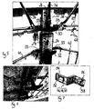
- the coupling device has a linkage with a first Z-shaped Tab 46, a second Z-shaped tab 48 and one Connecting rod 50 between the tabs 46, 48.
- the Tabs 46, 48 act as lever devices that are swivel with a turn of the handle shafts. For this point it as well as the tab 35 (see Fig. 7, the one of the tabs 46, 48, 35 shows in a detailed view) at one end 52 a square opening 54 with which onto a square pin that serves as a shaft (not explicitly shown) are set up.
- the tabs 46, 48, 35 have a fastening section 58 on.
- the lock device 12 is operated in the following way: from the outside it is over Rotation of the round handle 14 can be actuated.
- the rotation of the Round handle 14, with which the first inner handle 30 rotates, causes the first group of locking bars to move 34, 36, 38, these transmit the movement to the first arranged in the upper area of the door leaf Latch and / or latch devices. Solve the latter this results from the capture on the frame, the door leaf 10 is released in its upper area.
- the Rotation of the first inner handle 30 is via the coupling device 44 also on the second inner handle 32 transferred, the second lock 24 is actuated. This actuates the second group of locking bars 40, 42, so that the door leaf 10 also on its second, in the lower Area arranged latch and / or bolt devices is released.
- the door leaf 10 can the recessed grip 16 pulled out of its closed position and in be brought into its open position overhead. Analogous, only in the opposite way does the closing of the Door leaf 10, but provided that the latch or latch devices Have snap, an operation of the Locks are not absolutely necessary. An actuation the lock device 12 from the inside can optionally via one of the two inner handles 30, 32.
- the two locks 22 and 24 can be locked by means of their locking devices, the outside via the locking cylinder 18 and 20 or from the inside using the locking pins 26, 28 are operated, locked separately from each other be so that opening the door leaf 10 does not is possible.
- the by the lock cylinder 18, 20 each actuable locking mechanisms have the following functions: With a full turn of the key (Alternatively, shift the locking pin 26 or 28 in unlocking position) is constant actuation of the Lock 22 or 24 possible without a key. Both will Locking mechanisms brought into this release state, is opening and closing the gate from the outside possible without a key.
- the locking mechanism but also have one in addition to the locking function Actuation function: With a quarter turn of the key the respective lock can be operated, but is after locked again when the gate was closed.
- Modifications of the first embodiment include omitting one of the inner handles 30, 32 or modifications the coupling device 44, which instead the lever connecting rod gear also toothed or Chain gear or the like may include.
- the round handle 14 could be decoupled from the first inner handle 40 be so that an external actuation only decouples via round handle 14 (actuation of the first lock 22) and keys (actuation of the second lock 24) Internal actuation but coupled via an inner handle 30 or 32 can be done.
- the dual function (Locking and actuating) on one or both of the locking devices not realized.
- Actuators i.e. one of the handles 14, 30, 32 are operated.
- Another modification, not shown, of the first Embodiment contains more than two locks. This can be coupled together or only partially his.
- FIGS. 3 and 4 second embodiment of a lock device 62 for a Single-leaf overhead garage door explained.
- 3 shows the outside view, Fig. 4, the corresponding inside view of the area provided with the lock device 62 of the door leaf 10.
- the lock device 62 has in contrast to the lock device 12, no coupling device, but a second round handle 64. Otherwise, the structure is essentially the same as in the first embodiment. Same parts are with the same reference numerals, and for description the same is referred to the above statements.
- the second round handle 64 has one with the second inner handle 32 common handle shaft, via which the second lock 24 can be actuated.
- the gate is therefore through two separate, but spatially close to each other lying, operating different groups of locking bars Lockable systems.
- Each lock 22, 24 has its own own outside handle 14 or 64 and his own Lock cylinder 18 or 22.
- a third embodiment of the lock device 66 has from the outside shown in Fig. 1 and from the inside in Fig. 4 shape shown.
- the second lock 24 has the third embodiment 66 no external handle on and is also not coupled to the first lock 22. It is accordingly from the outside only by turning the key (1/4 Rotation). From the inside, it's over the second Inner handle 32 operable. That is locked or unlocked second lock 24 of the lock device 66 from the outside a whole turn of the key, from the inside over displacement of the second locking pin 28.
- FIG. 5 shows an interior view of a lock device 68 in a fourth embodiment. It essentially corresponds the second embodiment 62 (two outer handles 14, 64) or alternatively the third embodiment (An outer handle 14, dual function of the locking mechanism the one not provided with an external handle Lock 24, i.e. Actuation and locking via key), however, the first group of locking bars 34, 36, 38 two more locking bars 70 and 72 on. The other first locking rods 70 and 72 are operated via the first lock 22. The locking bars However, 70 and 72 do not lead to the top of the door leaf 10 arranged latch or latch devices. Much more 68 are additional latch or bolt devices just above the in the lock device the second lock 24 to be operated latch and bolt devices intended. These additional traps or Latching devices, also not shown are also operable by means of the first lock 22. The first lock 22 thus actuates five on the edge of the door leaf distributed latch or bolt devices.
- the coupling device can also the lock device 62 with two outer handles 14, 64 be provided. Instead of locking bars in principle also other motion transmission devices between the locks 22, 24 and the latch or bolt devices be provided.
- a lock device (12) with at least two locks (22, 24) suggested that preferably spatially close together at an ergonomically favorable location on the door leaf 10 are arranged, but in each case separate groups of locking bars (34, 36, 38; 40, 42) or the like Connections to deadbolt or latch devices actuate.
- the locks (22, 24) are separate from one another with its own locking devices, e.g. Lock cylinder (18, 20) include, lockable and unlockable.
- a preferred embodiment is a coupling device (44) for coupling individual actuators (30, 32) of the at least two locks (22, 24) are provided, so that they can be operated together in the unlocked state are.
Landscapes
- Engineering & Computer Science (AREA)
- Mechanical Engineering (AREA)
- Structural Engineering (AREA)
- Lock And Its Accessories (AREA)
- Gates (AREA)
Applications Claiming Priority (2)
| Application Number | Priority Date | Filing Date | Title |
|---|---|---|---|
| DE29817302U DE29817302U1 (de) | 1998-09-25 | 1998-09-25 | Schloßvorrichtung für ein Tor sowie damit versehenes Tor |
| DE29817302U | 1998-09-25 |
Publications (2)
| Publication Number | Publication Date |
|---|---|
| EP0989267A2 true EP0989267A2 (fr) | 2000-03-29 |
| EP0989267A3 EP0989267A3 (fr) | 2003-03-05 |
Family
ID=8063188
Family Applications (1)
| Application Number | Title | Priority Date | Filing Date |
|---|---|---|---|
| EP99118616A Withdrawn EP0989267A3 (fr) | 1998-09-25 | 1999-09-21 | Dispositif de verrouillage et porte avec un tel dispositif |
Country Status (2)
| Country | Link |
|---|---|
| EP (1) | EP0989267A3 (fr) |
| DE (1) | DE29817302U1 (fr) |
Cited By (1)
| Publication number | Priority date | Publication date | Assignee | Title |
|---|---|---|---|---|
| DE202006017308U1 (de) * | 2006-11-10 | 2008-03-13 | Arca Beteiligungen Gmbh | Nachrüstbarer Betätigungsantrieb für ein Schwenktor o.dgl. |
Families Citing this family (1)
| Publication number | Priority date | Publication date | Assignee | Title |
|---|---|---|---|---|
| DE10244652B4 (de) * | 2002-09-25 | 2005-07-14 | Hörmann KG Amshausen | Torblatthandgriff sowie Verwendung desselben |
Family Cites Families (3)
| Publication number | Priority date | Publication date | Assignee | Title |
|---|---|---|---|---|
| US2427909A (en) * | 1944-09-13 | 1947-09-23 | Edward N Howell | Locking device |
| GB9318045D0 (en) * | 1993-08-31 | 1993-10-20 | J E Reynolds & Company Ltd | Garage doors |
| GB9321141D0 (en) * | 1993-10-13 | 1993-12-01 | Boydell John M | Improvements in up and over garage doors |
-
1998
- 1998-09-25 DE DE29817302U patent/DE29817302U1/de not_active Expired - Lifetime
-
1999
- 1999-09-21 EP EP99118616A patent/EP0989267A3/fr not_active Withdrawn
Cited By (1)
| Publication number | Priority date | Publication date | Assignee | Title |
|---|---|---|---|---|
| DE202006017308U1 (de) * | 2006-11-10 | 2008-03-13 | Arca Beteiligungen Gmbh | Nachrüstbarer Betätigungsantrieb für ein Schwenktor o.dgl. |
Also Published As
| Publication number | Publication date |
|---|---|
| EP0989267A3 (fr) | 2003-03-05 |
| DE29817302U1 (de) | 2000-02-03 |
Similar Documents
| Publication | Publication Date | Title |
|---|---|---|
| DE3447748C2 (fr) | ||
| EP1932989B1 (fr) | Système de fermeture pour portes, fenêtres ou analogues, en particulier crémone-serrure à fonction d'urgence et de verrouillage à plusieurs points | |
| DE69503354T3 (de) | Betätigungsvorrichtung für kraftfahrzeugtürschlösse | |
| DE69636534T2 (de) | Schlossystem für Fahrzeugstüre | |
| DE60306654T2 (de) | Türschliessmechanismus | |
| EP0807736B1 (fr) | Serrure encastrée | |
| DE10194835B4 (de) | Hebelverschluss | |
| EP0945572A2 (fr) | Ensemble de serrure de porte, de préférence crémone-serrure | |
| EP1574644A2 (fr) | Système de verrouillage pour portes, fenêtres ou similaires, notamment crémone-serrure avec fonction anti-panique et avec plusieurs points de condamnation | |
| EP1049846B1 (fr) | Serrure pour porte en verre avec un element lateral fixe en verre | |
| DE3425565A1 (de) | Treibstangenschloss | |
| DE4041218A1 (de) | Wahlweise selbstverriegelndes einriegelschloss | |
| DE60118862T2 (de) | Türblatt mit automatischem Sicherheitsverriegelungssystem | |
| DE4244414C2 (de) | Verschluß für Fenster, Türen u. dgl. | |
| EP3144455B1 (fr) | Dispositif de verrouillage | |
| DE60114431T2 (de) | Türriegel mit hakenbolzen | |
| EP1908899A2 (fr) | Système de verrouillage | |
| EP1160398B1 (fr) | Serrure à commande électrique | |
| EP2400083B1 (fr) | Serrure électronique protégée contre la manipulation | |
| EP0989267A2 (fr) | Dispositif de verrouillage et porte avec un tel dispositif | |
| EP2998475B1 (fr) | Levier de jour pour une serrure a battant passif | |
| DE102007010437B4 (de) | Komfortöffnungs-Schloss | |
| DE4434873C2 (de) | Schließrahmenteil mit automatischem Einbruchschutz durch Hakenvorschub und Fallenarretierung | |
| DE2605763C3 (de) | Treibstangenschloß mit Falle | |
| EP0738814A1 (fr) | Dispositif sur une serrure de porte |
Legal Events
| Date | Code | Title | Description |
|---|---|---|---|
| PUAI | Public reference made under article 153(3) epc to a published international application that has entered the european phase |
Free format text: ORIGINAL CODE: 0009012 |
|
| AK | Designated contracting states |
Kind code of ref document: A2 Designated state(s): AT BE CH CY DE DK ES FI FR GB GR IE IT LI LU MC NL PT SE |
|
| AX | Request for extension of the european patent |
Free format text: AL;LT;LV;MK;RO;SI |
|
| PUAL | Search report despatched |
Free format text: ORIGINAL CODE: 0009013 |
|
| AK | Designated contracting states |
Kind code of ref document: A3 Designated state(s): AT BE CH CY DE DK ES FI FR GB GR IE IT LI LU MC NL PT SE Designated state(s): AT BE CH CY DE DK ES FI FR GB GR IE IT LI LU MC NL PT SE |
|
| AX | Request for extension of the european patent |
Extension state: AL LT LV MK RO SI |
|
| RIC1 | Information provided on ipc code assigned before grant |
Ipc: 7E 05B 65/00 B Ipc: 7E 05B 53/00 B Ipc: 7E 05C 9/06 B Ipc: 7E 05C 9/04 B Ipc: 7E 05B 63/14 A |
|
| 17P | Request for examination filed |
Effective date: 20030517 |
|
| AKX | Designation fees paid |
Designated state(s): DE FR GB IT NL |
|
| 17Q | First examination report despatched |
Effective date: 20031219 |
|
| GRAP | Despatch of communication of intention to grant a patent |
Free format text: ORIGINAL CODE: EPIDOSNIGR1 |
|
| STAA | Information on the status of an ep patent application or granted ep patent |
Free format text: STATUS: THE APPLICATION IS DEEMED TO BE WITHDRAWN |
|
| 18D | Application deemed to be withdrawn |
Effective date: 20050727 |