EP0989306A1 - Kompressor und Pumpensystem mit alternierendem Betrieb des Kompressorteils und zugehörigem Verfahren - Google Patents
Kompressor und Pumpensystem mit alternierendem Betrieb des Kompressorteils und zugehörigem Verfahren Download PDFInfo
- Publication number
- EP0989306A1 EP0989306A1 EP99402084A EP99402084A EP0989306A1 EP 0989306 A1 EP0989306 A1 EP 0989306A1 EP 99402084 A EP99402084 A EP 99402084A EP 99402084 A EP99402084 A EP 99402084A EP 0989306 A1 EP0989306 A1 EP 0989306A1
- Authority
- EP
- European Patent Office
- Prior art keywords
- compression
- liquid
- fluid
- section
- gas
- Prior art date
- Legal status (The legal status is an assumption and is not a legal conclusion. Google has not performed a legal analysis and makes no representation as to the accuracy of the status listed.)
- Granted
Links
Images


Classifications
-
- E—FIXED CONSTRUCTIONS
- E21—EARTH OR ROCK DRILLING; MINING
- E21B—EARTH OR ROCK DRILLING; OBTAINING OIL, GAS, WATER, SOLUBLE OR MELTABLE MATERIALS OR A SLURRY OF MINERALS FROM WELLS
- E21B43/00—Methods or apparatus for obtaining oil, gas, water, soluble or meltable materials or a slurry of minerals from wells
- E21B43/34—Arrangements for separating materials produced by the well
-
- E—FIXED CONSTRUCTIONS
- E21—EARTH OR ROCK DRILLING; MINING
- E21B—EARTH OR ROCK DRILLING; OBTAINING OIL, GAS, WATER, SOLUBLE OR MELTABLE MATERIALS OR A SLURRY OF MINERALS FROM WELLS
- E21B43/00—Methods or apparatus for obtaining oil, gas, water, soluble or meltable materials or a slurry of minerals from wells
- E21B43/12—Methods or apparatus for controlling the flow of the obtained fluid to or in wells
- E21B43/121—Lifting well fluids
-
- F—MECHANICAL ENGINEERING; LIGHTING; HEATING; WEAPONS; BLASTING
- F04—POSITIVE - DISPLACEMENT MACHINES FOR LIQUIDS; PUMPS FOR LIQUIDS OR ELASTIC FLUIDS
- F04D—NON-POSITIVE-DISPLACEMENT PUMPS
- F04D31/00—Pumping liquids and elastic fluids at the same time
-
- E—FIXED CONSTRUCTIONS
- E21—EARTH OR ROCK DRILLING; MINING
- E21B—EARTH OR ROCK DRILLING; OBTAINING OIL, GAS, WATER, SOLUBLE OR MELTABLE MATERIALS OR A SLURRY OF MINERALS FROM WELLS
- E21B2200/00—Special features related to earth drilling for obtaining oil, gas or water
- E21B2200/22—Fuzzy logic, artificial intelligence, neural networks or the like
Definitions
- the present invention relates to an alternating compression-pumping system of a multiphase fluid having a composition which may vary over time.
- the composition can successively present a large quantity of gas, established over a long period of use, but also a low rate of gas over a period of time which can cause engorgement of a separator arranged upstream of the part of the system having the function to communicate energy to the fluid.
- two-phase pumping is commonly used to refer to a supply of energy to a fluid composed of a liquid phase and a gaseous phase
- compression better suited to designate a transfer of energy to a compressible two-phase fluid, in particular when it is characterized by a high gas / liquid volume ratio (GLR under real temperature and pressure) high.
- the compression system includes means for performing the switching of this compression section from gas mode to liquid mode and Conversely.
- the present invention relates to an alternating compression-pumping system, making it possible to communicate energy to a multiphase fluid having a composition variable over time, for example a variation in the amount of gas phase and the amount of liquid phase.
- the compression system can include at least one recycling conduit for a at least fraction of essentially gaseous fluid from the compression-pumping section to the separation device.
- the system includes, for example, a recycling conduit of at least a fraction of the essentially liquid fluid from the pumping section to the separation device.
- the compression section comprises for example at minus one stage allowing separation of the gas phase and the liquid phase in the form of droplets.
- the present invention also relates to a method for communicating the energy at each of the phases of a multiphase fluid, the fluid comprising at least one liquid phase and at least one gaseous phase, the amount of the essentially liquid phase and the quantity of the essentially gaseous phase can vary over time, the phase gas being sent to a compression-pumping section and the liquid phase being sent to a pumping section or to a compression-pumping section in alternating operation, the sections being part of a compression-pumping system.
- the initial speed of rotation N P1 can be varied towards a speed of rotation N P2 , the speed of rotation N P2 being chosen such that the value of the discharge pressure of the compression section obtained during the passage of a gaseous fluid is substantially identical to the discharge pressure value when the section is traversed by a liquid fluid and conversely vary the speed of rotation when changing from the mode P 2 to the mode P 1 .
- the step of separating the droplets of liquid from the gaseous phase is continued.
- the interior of a compression stage arranged at the level of the compression-pumping section alternated.
- At least a fraction of the gas phase from the compression section to the separation device so as to maintain a minimum flow of fluid in the compression section.
- the stage of separation is for example carried out in a separation device.
- the system and the method according to the invention are used for example to transfer a certain energy in the liquid phase and in the gas phase of a petroleum effluent. They can also be used to transfer some energy to the liquid phase and to the gas phase of a wet gas, such as a condensate gas or an associated gas.
- a wet gas such as a condensate gas or an associated gas.
- the invention relates more generally to a compression-pumping system alternating to communicate energy to one or more fluids, said fluids can be liquid or gaseous.
- the invention also relates to an associated method for communicating energy to a fluid which can be either essentially liquid or essentially gaseous.
- the speed of rotation of the cross section is adjusted, for example compression-pumping with alternating operation.
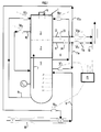
- FIG. 1 represents an exemplary embodiment for the compression-pumping system comprising the features of the invention, given by way of illustration and in no way limiting, to better understand the operating principle.
- This system makes it possible to raise the pressure of a multiphase fluid and in particular the pressure for each of the constituent phases.
- gas phase is used to designate a fluid essentially gaseous or a gas resulting from the separation of the multiphase fluid
- liquid phase an essentially liquid fluid or a liquid
- the alternating compression-pumping system is for example integrated in the same enclosure or casing 1. It comprises at least one pumping section 2 adapted to a fluid essentially liquid and at least one compression section 3 whose characteristics techniques are adapted to an essentially gaseous fluid but which can also function for an essentially liquid fluid.
- the compression section is designated under the expression "alternating pumping section" for reasons of simplification.
- Each of the compression 3 or pumping 2 sections comprises several stages composed of impellers followed by rectifiers. These impellers and rectifiers are chosen among those usually used in the fields of pumping and compression of fluids comprising several phases or of monophasic fluids.
- the compression section 3 may include one or more inlet stages which will be adapted to finalize the separation of the multiphase fluid according to methods classics used by the skilled person. This embodiment is advantageous when the gas has liquid droplets even if they are weak quantities.
- the separator can be integral with or separate from the casing.
- the conduit 11 can be divided into two conduits 11a, 11b.
- the duct 11a is equipped with a control valve Vl1 and makes it possible to recycle a at least fraction of the essentially liquid phase to the separator 5.
- This fraction of liquid may, without departing from the scope of the invention, come from an external source of liquid connected to conduit 11a.
- the duct 12 is provided for example with a flow measurement device 13.
- This duct is divided for example into two ducts 12a, 12b.
- the conduit 12a is provided with a control valve Vg1 which allows the recycling of a fraction of the compressed gas to the supply line so as to reintroduce it into the separator.
- This recycling circuit acts as a protection circuit for the section of compression.
- the conduit 12b comprises for example a valve Vg2 which allows the gas to be evacuated.
- the protection circuit (12a, Vg1) makes it possible to maintain a minimum flow so as to protect the system against highly destructive flow fluctuations at reduced flow.
- One of the ways of implementing it is given in the following description.
- the recycling system (11a, Vl1) allows to maintain a minimum flow of liquid so as to protect the alternating compression-pumping system against vibrations generated at reduced flow.
- the conduits 11b and 12b can be combined into a single conduit 16 to evacuate the fluid to a place of destination or a place of treatment.
- the separator 5 and the various aforementioned conduits are optionally equipped with means making it possible to determine the pressure and the temperature, such as sensors C P , C T , not shown for reasons of simplification of the figure.
- the alternating compression-pumping system also includes means for determine the speed N of rotation of the shaft 4 supporting the impellers of the sections of compression and pumping.
- the separator 5 is equipped with means for example one or more sensors C L to determine the level of the liquid-gas interface.
- this or these sensors are capable of monitoring the evolution of the level of liquid inside the separator.
- All the measuring devices are connected to a control-command system 15 who is able to memorize the different information, process it and send signals allowing to act on the different valves equipping the system according to a method an example of which is given below.
- the control-command system 15 is thus capable of controlling the various operations given as a nonlimiting and illustrative example below.
- the system remains in this state as long as the liquid-gas interface does not move away from the threshold value L 3 , this is controlled for example using the level sensor C L.
- the fluid sent to the compression section is an essentially gaseous fluid.
- control-command system 15 will act on the different valves to tilt the compression-pumping section from an operating mode for the gas to an operating mode for the liquid, and therefore passing an essentially liquid fluid through the compression section.
- the control-command system 15 acts so that the valve Vl1 gradually closes and the valve Vl2 gradually opens. Their openings are subjected to a PID or other type of regulation mode, known to those skilled in the art.
- the reverse logic applies.
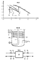
- the references MP1, MP2 and PS correspond to operation in mode P 1 , P 2 or in mode P 1 stabilized around the level L 3 .
- the rotation speed can be reduced according to a substantially linear law.
- control-command system acting on the valves, has positioned the latter in intermediate states (or preliminary states) in the state in which they will have to be put for the passage from the operating mode of P 1 to the operating mode P 2 .
- the control-command system 15 acts to decrease the speed of rotation to the speed of rotation N P2 and completely close the valve Vg3, fully open the valve Vl3 so as to direct the liquid towards the compression section and open the valve Vl4 (reference> L0 (t1) in diagram 2B in Figure 2).
- the switching of the operating mode being completed, the compression-pumping system 15 will open the valve Vg2 so as to evacuate the liquid through the compression section, and close the valve Vg1 entirely. (reference> L0 (t2) on diagram 2B in figure 2)
- valve Vl4 makes it possible to limit the mismatching of the stages of compression during an operation with a very little compressible phase (phase essentially liquid) as shown in Figure 3.
- the inlet liquid flow rate may be insufficient to maintain the liquid level at L 3 .
- the control-command system 15 acts so that the valve Vl2 closes completely, so as to prevent entry of the gas phase into the liquid section and to increase the opening. of valve Vl1, so as to allow operation at a flow rate greater than the minimum flow rate below which the vibrations appear.
- This operating mode is maintained while the liquid level is below L 4 .
- the valve Vl2 resumes the opening corresponding to a normal operating case and the opening of the valve Vl1 is adjusted so as to regulate the liquid level around L 3 .
- the so-called compression section is crossed by an essentially liquid phase, therefore having a high density.
- the compression ratio can then be very high and even too high compared to the mechanical strength of the impellers, the casing and the installations usually used and located downstream of the casing.
- the speed of rotation Np 2 is chosen so that the discharge pressure is approximately equal to that obtained in mode P 1 , taking into account the densities of each phase, and so that N P2 ⁇ N P1 .
- valve positions and the speed of rotation are maintained in the state which followed the changeover as long as the level remains higher than L 2 so as to avoid too frequent mode changes, in the case for example of changes from P 1 to P 2 and from P 2 to P 1 triggered by the same level of liquid.
- the control-command system gradually switches the operating mode of the compression system from mode P 2 to mode P 1 .
- the first phase of the changeover (diagram 2B in Figure 2 ⁇ L2 (t3)) consists of fully open the valve Vg3, partially open the valve Vg1 and close the valves Vl3 and Vl4 so as to direct the gaseous fluid contained in the separator towards the section of compression.
- valve Vg2 (practically entirely, L3 (t5)) so as to allow the evacuation of the gas when the pressure at the outlet of the compression section reaches a pressure greater than the pressure measured downstream of the junction Js, put the valve Vl2 in an open position substantially identical to the position corresponding to the normal operation previously defined and open the valve Vl1 so as to maintain the liquid level around L 3 .
- L3 (t5) we observe the start of the closing of valve Vg1.
- the control-command system acts to close the valve Vg1 entirely (diagram 2A in FIG. 2 L3 (t6)) and to reset the value of the rotation speed to a corresponding value substantially at the value Np1 (mode P 1 ).
- the opening of the valve Vg1 is maintained in a state such that the gas flow is greater than the flow corresponding to the minimum authorized flow (anti-pumping protection).
- This flow rate value is specified in relation to the characteristics of the compression section.
- FIG. 3 represents, in a flow coefficient diagram (on the abscissa), pressure coefficient (on the ordinate), the evolution of operating points of the section of compression-pumping with alternating operation, when the compression-pumping system is equipped with means making it possible to adapt at least one series of compression stages to the pumping a liquid, knowing that these compression stages were initially chosen by compared to an essentially gaseous fluid.
- These means are for example in the example given one or more extraction pipes fitted with valves to control the passage of fluids.
- adaptive of a stage means in the context of the present invention, the operation of a stage at a rate corresponding to the point of best efficiency, point which is known to the specialist in compression machines.
- Flow and pressure coefficients of a stage are dimensionless quantities which are respectively proportional to the flow rate of the stage and at the head, two known parameters of the same specialist.
- the compression section is made up of four stages: references E 1 to E 4 .
- the adaptation of the stages is represented by the points A 1 to A 4 , the volume flow rates decreasing from the first to the last stage, taking into account the compressibility of the gas.
- stage E 2 point B 2
- stage E 3 the stages situated upstream and downstream of this stage are generally very ill-adapted.
- stage E 4 (represented by point B 4 )
- it will reduce the energy supplied to the fluid (compression ratio less than 1) by stages E 1 to E 3 .
- the compression system comprises at least one conduit extraction 10 disposed between two stages of compression and a valve Vl4.
- the fraction of fluid extracted from the compression section can be sent to the separator 5 or else towards a point external to the compression-pumping system according to the invention.
- the flow rate of extracted liquid is determined by appropriate sizing of the duct extraction 10 (length and diameter) or by the introduction of an energy dissipating organ known to those skilled in the art (restriction, orifice, type valve or anything) in this conduit.
- FIG. 4A represents an alternative embodiment comprising means allowing optimize the fluid separation step.
- This variant comprises a static separator 5 having a reduced volume compared the dimensions of the separators conventionally used upstream of the machines monophasic.
- the rotation can for example be obtained by arranging the aspirations of the conduits (7, 8, 9) tangentially to the wall of the separator 5 and substantially perpendicular to the axis of symmetry of the separator (at the center of symmetry of the separator) (not shown in FIG. 4A) as described in the applicant's patent application FR 98/00933.
- the suction lines 7 and 9 are arranged below level L 4 while the suction line 8 is disposed above level L 0 .
- Dynamic separation can be achieved by an arrangement of several elements such as those depicted in Figure 4A
- the rotation shaft 4 common to the pumping section 2 and to the compression section 3 enters the static separator 5 of FIG. 4A and serves as support for disc series.
- the diameter of the shaft 4 or of a part of this shaft supporting the Dg disks is dimensioned according to the torque to be transmitted and the required rigidity.
- the tree could be consisting of several elements, the coupling being done by gear, flexible coupling, magnetic or whatever.
- Dg discs are for example arranged so as to avoid the operation of discs at the oil-gas interface and the formation of emulsion.
- the diameter of these discs and the distance between the discs in the same series can be determined according to the degree of separation desired upstream of the sections of pumping and compression. For example, we will determine these parameters according to limit diameters for droplets. These parameters can be calculated using a code three-dimensional calculation available to those skilled in the art.
- a duct 20 of helical shape is arranged around the duct 7 allowing the passage of the liquid phase towards the pumping section and which is arranged substantially at the level of the central axis of the separator.
- the gas containing the droplets of liquid enters through inlet 21.
- the droplets are deposited along the wall of the pipe by the action of a centrifugal force.
- the pipe being ascending in this embodiment which is in no way limiting, the liquid deposited falls back into the separator through the gas inlet 22 while the gas leaves at point 23 (inlet 8).
- the characteristics of the helical tube are dimensioned so as to allow the liquid deposited by entrance 22.
- the sealing device 19, shown in FIG. 4A makes it possible to avoid migration phases between the compression and pumping sections.
- An example of a device is detailed in the aforementioned patent application FR-98 / 00.933, including technical teaching relating to this sealing means is incorporated by reference.
- level measurement can be carried out for example using of three sensors operating according to the principle of majority logic (when a sensor provides information different from the other two, the information from the first is discarded in favor of the other two).
- lines 12a and 11a can also be used so as to avoid the operation of the compression section and the pumping section in the reduced flow rate which can lead to rapid damage to the compression section (anti-pumping) and the generation of pressure and vibration fluctuations with regard to the pumping section.
- a liquid rate and displacement speed measurement system can be installed in upstream of the equipment, so as to anticipate actions on the valves as well as on the speed regulation.
- Fuzzy logic regulation taking into account a large number of parameters (for example, the level of liquid in the separator flask, the degree of opening of the assembly valves, the rate of liquid and its speed of movement upstream of the system compression - pumping) can be implemented to allow better optimization of production compared to conventional regulation while ensuring better protection of equipment.
- This device is for example arranged upstream of the junction of the conduits 6 and 12a. he works on the principle of an increase in pressure drops for the same speed when the liquid level increases and from an accentuation of this effect to a short distance from the input of the two-phase compression device.
- the device could be consisting of a diameter restriction, an orifice, a valve or any other member can cause a pressure drop.
- FIG. 5 schematically represents a compression-pumping system alternating suitable for example for all areas of application where one must communicate energy to several fluids, one of which is essentially liquid and the other essentially gaseous.
- the alternating compression-pumping system includes a section of compression 50 with alternating gas-liquid operation, having one of the characteristics described in the compression-pumping section described in Figure 1.
- Two inlet pipes (51, 52) for example a pipe for the introduction of the fluid liquid and a conduit for the introduction of gas.
- Means making it possible to determine upstream the nature of the fluid which arrives in the compression system, arranged for example on the inlet conduits.
- a fluid outlet conduit 53 having acquired energy having acquired energy.
- An evacuation duct 54 for an essentially liquid fluid the majority of the liquid being evacuated after having acquired energy through conduit 53 and the rest passes through the conduit 54 so as to allow the adaptation of the compression section to the passage of the liquid.
- Control means substantially identical to the reference means 15 and described above. These means take into account in particular the result of the determination of the fluid arriving to control the operating tilting of the compression-pumping section in P1 mode or in P2 mode.
- valves 55, 56, 57 and 58 disposed respectively on the conduits 51, 52, 53 and 54. These valves ensure the passage or not of the fluid essentially liquid or essentially gaseous fluid to the operating compression section alternating or from the alternating compression section.
Landscapes
- Engineering & Computer Science (AREA)
- Life Sciences & Earth Sciences (AREA)
- Mining & Mineral Resources (AREA)
- Geology (AREA)
- Fluid Mechanics (AREA)
- Environmental & Geological Engineering (AREA)
- Physics & Mathematics (AREA)
- General Life Sciences & Earth Sciences (AREA)
- Geochemistry & Mineralogy (AREA)
- General Engineering & Computer Science (AREA)
- Mechanical Engineering (AREA)
- Structures Of Non-Positive Displacement Pumps (AREA)
- Separation By Low-Temperature Treatments (AREA)
Applications Claiming Priority (2)
| Application Number | Priority Date | Filing Date | Title |
|---|---|---|---|
| FR9811990 | 1998-09-24 | ||
| FR9811990A FR2783884B1 (fr) | 1998-09-24 | 1998-09-24 | Systeme de compression-pompage comportant une section de compression en fonctionnement alterne et son procede |
Publications (2)
| Publication Number | Publication Date |
|---|---|
| EP0989306A1 true EP0989306A1 (de) | 2000-03-29 |
| EP0989306B1 EP0989306B1 (de) | 2005-11-09 |
Family
ID=9530833
Family Applications (1)
| Application Number | Title | Priority Date | Filing Date |
|---|---|---|---|
| EP99402084A Expired - Lifetime EP0989306B1 (de) | 1998-09-24 | 1999-08-19 | Kompressor und Pumpensystem mit alternierendem Betrieb des Kompressorteils und zugehörigem Verfahren |
Country Status (5)
| Country | Link |
|---|---|
| US (1) | US6296690B1 (de) |
| EP (1) | EP0989306B1 (de) |
| DE (1) | DE69928196D1 (de) |
| FR (1) | FR2783884B1 (de) |
| NO (1) | NO994618L (de) |
Cited By (2)
| Publication number | Priority date | Publication date | Assignee | Title |
|---|---|---|---|---|
| WO2009131462A3 (en) * | 2008-04-21 | 2010-01-07 | Statoilhydro Asa | Gas compression system |
| AU2015202860B2 (en) * | 2008-04-21 | 2016-09-22 | Statoil Petroleum As | Combined multi-phase pump and compressor unit and gas compression system |
Families Citing this family (7)
| Publication number | Priority date | Publication date | Assignee | Title |
|---|---|---|---|---|
| US7488159B2 (en) * | 2004-06-25 | 2009-02-10 | Air Products And Chemicals, Inc. | Zero-clearance ultra-high-pressure gas compressor |
| GB2418213B (en) * | 2004-09-21 | 2009-09-09 | Caltec Ltd | Well start-up system and process |
| US7410348B2 (en) * | 2005-08-03 | 2008-08-12 | Air Products And Chemicals, Inc. | Multi-speed compressor/pump apparatus |
| WO2010129749A1 (en) * | 2009-05-06 | 2010-11-11 | Curtiss-Wright Electro-Mechanical Corporation | Gas tolerant subsea pump |
| US9879663B2 (en) | 2013-03-01 | 2018-01-30 | Advanced Cooling Technologies, Inc. | Multi-phase pump system and method of pumping a two-phase fluid stream |
| EP3161320B1 (de) * | 2014-06-24 | 2021-02-24 | Sterling Industry Consult GmbH | Seitenkanalpumpe |
| US20160138595A1 (en) * | 2014-11-13 | 2016-05-19 | General Electric Company | Subsea fluid processing system with intermediate re-circulation |
Citations (4)
| Publication number | Priority date | Publication date | Assignee | Title |
|---|---|---|---|---|
| US3366061A (en) * | 1965-07-09 | 1968-01-30 | Nash Engineering Co | Device for pumping liquid and gas |
| GB2014862A (en) * | 1978-02-24 | 1979-09-05 | Inst Francais Du Petrole | Methods of and apparatus for conveying diphasic fluids through pipes |
| EP0549439A1 (de) * | 1991-12-27 | 1993-06-30 | Institut Français du Pétrole | Verfahren und Vorrichtung für die Optimierung des Transports einer Mehrphasenflüssigkeit durch Pumpen |
| GB2273958A (en) * | 1992-12-29 | 1994-07-06 | Inst Francais Du Petrole | Pumping multiphase fluid. |
Family Cites Families (14)
| Publication number | Priority date | Publication date | Assignee | Title |
|---|---|---|---|---|
| US1387748A (en) * | 1921-02-24 | 1921-08-16 | Anti Corrosion Engineering Com | Apparatus for removing gases from water |
| US2005466A (en) * | 1931-09-08 | 1935-06-18 | Bour Harry E La | Self priming pump |
| US2213857A (en) * | 1937-09-08 | 1940-09-03 | Sf Bowser & Co Inc | Pumping and separating mechanism |
| US2552264A (en) * | 1949-02-25 | 1951-05-08 | Edwards Miles Lowell | Vapor separating pump |
| US3050008A (en) * | 1958-12-30 | 1962-08-21 | Gilbert & Barker Mfg Co | Elimination of air and vapors from a centrifugal pump |
| US4273562A (en) * | 1979-10-01 | 1981-06-16 | A. Ahlstrom Osakeyhtio | Method and apparatus for pumping gaseous liquids and separating the gaseous components therefrom |
| US4435193A (en) * | 1980-04-07 | 1984-03-06 | Kamyr Ab | Controlling operation of a centrifugal pump |
| US4600413A (en) * | 1984-12-10 | 1986-07-15 | Sundstrand Corporation | Centrifugal deaerator and pump |
| FR2589957B1 (fr) | 1985-11-08 | 1989-11-03 | Bertin & Cie | Compresseur de fluide gazeux, associe a un separateur gaz-liquide |
| FI872967A7 (fi) * | 1987-07-06 | 1989-01-07 | Ahlstroem Oy | Pump och foerfarande foer separering av gas med pumpen ur mediet som skall pumpas. |
| FR2665224B1 (fr) | 1990-07-27 | 1992-11-13 | Inst Francais Du Petrole | Dispositif de pompage ou de compression polyphasique et son utilisation. |
| US5375976A (en) | 1990-07-27 | 1994-12-27 | Institut Francais Du Petrole | Pumping or multiphase compression device and its use |
| SE508348C2 (sv) * | 1996-03-27 | 1998-09-28 | Sunds Defibrator Ind Ab | Sätt och anordning vid pumpning av ett gasinnehållande medium där gasen evakueras med hjälp av sugverkan från en ejektor |
| FR2774136B1 (fr) | 1998-01-28 | 2000-02-25 | Inst Francais Du Petrole | Dispositif de compression-pompage monoarbre associe a un separateur |
-
1998
- 1998-09-24 FR FR9811990A patent/FR2783884B1/fr not_active Expired - Fee Related
-
1999
- 1999-08-19 EP EP99402084A patent/EP0989306B1/de not_active Expired - Lifetime
- 1999-08-19 DE DE69928196T patent/DE69928196D1/de not_active Expired - Lifetime
- 1999-09-23 NO NO994618A patent/NO994618L/no not_active Application Discontinuation
- 1999-09-24 US US09/404,655 patent/US6296690B1/en not_active Expired - Fee Related
Patent Citations (4)
| Publication number | Priority date | Publication date | Assignee | Title |
|---|---|---|---|---|
| US3366061A (en) * | 1965-07-09 | 1968-01-30 | Nash Engineering Co | Device for pumping liquid and gas |
| GB2014862A (en) * | 1978-02-24 | 1979-09-05 | Inst Francais Du Petrole | Methods of and apparatus for conveying diphasic fluids through pipes |
| EP0549439A1 (de) * | 1991-12-27 | 1993-06-30 | Institut Français du Pétrole | Verfahren und Vorrichtung für die Optimierung des Transports einer Mehrphasenflüssigkeit durch Pumpen |
| GB2273958A (en) * | 1992-12-29 | 1994-07-06 | Inst Francais Du Petrole | Pumping multiphase fluid. |
Cited By (8)
| Publication number | Priority date | Publication date | Assignee | Title |
|---|---|---|---|---|
| WO2009131462A3 (en) * | 2008-04-21 | 2010-01-07 | Statoilhydro Asa | Gas compression system |
| AU2009238753B2 (en) * | 2008-04-21 | 2015-04-23 | Equinor Energy As | Gas compression system |
| US9032987B2 (en) | 2008-04-21 | 2015-05-19 | Statoil Petroleum As | Gas compression system |
| AU2015202860B2 (en) * | 2008-04-21 | 2016-09-22 | Statoil Petroleum As | Combined multi-phase pump and compressor unit and gas compression system |
| AU2015202855B2 (en) * | 2008-04-21 | 2016-09-22 | Statoil Petroleum As | Gas compression system and method of flow conditioning |
| EA024584B1 (ru) * | 2008-04-21 | 2016-10-31 | Статойл Петролеум Ас | Система сжатия газа |
| US9784075B2 (en) | 2008-04-21 | 2017-10-10 | Statoil Petroleum As | Gas compression system |
| US9784076B2 (en) | 2008-04-21 | 2017-10-10 | Statoil Petroleum As | Gas compression system |
Also Published As
| Publication number | Publication date |
|---|---|
| US6296690B1 (en) | 2001-10-02 |
| NO994618D0 (no) | 1999-09-23 |
| EP0989306B1 (de) | 2005-11-09 |
| DE69928196D1 (de) | 2005-12-15 |
| NO994618L (no) | 2000-03-27 |
| FR2783884B1 (fr) | 2000-10-27 |
| FR2783884A1 (fr) | 2000-03-31 |
Similar Documents
| Publication | Publication Date | Title |
|---|---|---|
| FR2774136A1 (fr) | Dispositif de compression-pompage monoarbre associe a un separateur | |
| FR2748533A1 (fr) | Systeme de pompage polyphasique et centrifuge | |
| FR2479870A1 (fr) | Dispositif et procede pour separer un gaz d'une suspension de fibres | |
| EP0989306B1 (de) | Kompressor und Pumpensystem mit alternierendem Betrieb des Kompressorteils und zugehörigem Verfahren | |
| EP0781929B1 (de) | Vorrichtung zum Pumpen oder Verdichten eines mehrphasigen Fluids mit einer Tandem Beschaufelung | |
| EP2683458A1 (de) | Zyklonstromabscheider | |
| CA2258350A1 (fr) | Dispositif de compression de gaz humide comportant un etage de compression/separation integrees | |
| FR2551804A1 (fr) | Dispositif utilisable notamment pour le pompage d'un fluide tres visqueux et/ou contenant une proportion notable de gaz, particulierement pour la production de petrole | |
| FR2722425A1 (fr) | Systeme destine a la compression de l'air et a l'extraction d'azote de l'air comprime | |
| FR2771029A1 (fr) | Dispositif pour la separation des constituants d'un melange heterogene | |
| CA2671216A1 (fr) | Dispositif de separation de particules solides et installation hydraulique comprenant un tel dispositif | |
| EP2281110A2 (de) | Vorrichtung und verfahren zum druckausgleich in einem turbostrahllagergehäuse | |
| FR2652610A1 (fr) | Procede de pompage de melange liquide gaz dans un puits d'extraction petrolier et dispositif de mise en óoeuvre du procede. | |
| FR2997870A1 (fr) | Dispositif de filtration d'eau de piscine | |
| EP3137756A1 (de) | Flüssigkeitsversorgungskreislauf mit variablen geometrien für eine turbomaschine ohne volumetrische pumpe | |
| EP0892886B1 (de) | Pumpanlage für einen zweiphasigen flüssigkeits-/gasausfluss | |
| EP3569866A1 (de) | Kompressor und verfahren zur kontrolle des durchsatzes | |
| WO1999042732A1 (fr) | Cellule de pompage d'un effluent polyphasique et pompe comportant au moins une de ces cellules | |
| EP2366868A1 (de) | Verfahren zur Senkung des Bohrlochinjektionsdruckes einer Polymerlösung ohne Scherkraft- Abbau | |
| EP0034975B1 (de) | Verfahren zur Reinigung von teilchenförmigem Material und Vorrichtung dafür, Vorrichtung zur Durchführung dieses Verfahrens | |
| BE1021893B1 (fr) | Groupe de pompage, station de pompage, aire de pompage et methode de pompage d'un liquide. | |
| FR2787836A1 (fr) | Impulseur diphasique helico-radio-axial avec carenage incurve | |
| EP3097016B1 (de) | Verfahren und system zur verwaltung von grauwasser in einem flugzeug | |
| FR2697870A1 (fr) | Pompe axiale à faible débit. | |
| FR2912931A1 (fr) | Dispositif pour separer des molecules et/ou particules dispersees dans un fluide |
Legal Events
| Date | Code | Title | Description |
|---|---|---|---|
| PUAI | Public reference made under article 153(3) epc to a published international application that has entered the european phase |
Free format text: ORIGINAL CODE: 0009012 |
|
| AK | Designated contracting states |
Kind code of ref document: A1 Designated state(s): CH DE GB IT LI |
|
| AX | Request for extension of the european patent |
Free format text: AL;LT;LV;MK;RO;SI |
|
| 17P | Request for examination filed |
Effective date: 20000929 |
|
| AKX | Designation fees paid |
Free format text: CH DE GB IT LI |
|
| 17Q | First examination report despatched |
Effective date: 20040802 |
|
| GRAP | Despatch of communication of intention to grant a patent |
Free format text: ORIGINAL CODE: EPIDOSNIGR1 |
|
| GRAS | Grant fee paid |
Free format text: ORIGINAL CODE: EPIDOSNIGR3 |
|
| GRAA | (expected) grant |
Free format text: ORIGINAL CODE: 0009210 |
|
| AK | Designated contracting states |
Kind code of ref document: B1 Designated state(s): CH DE GB IT LI |
|
| PG25 | Lapsed in a contracting state [announced via postgrant information from national office to epo] |
Ref country code: IT Free format text: LAPSE BECAUSE OF FAILURE TO SUBMIT A TRANSLATION OF THE DESCRIPTION OR TO PAY THE FEE WITHIN THE PRE;WARNING: LAPSES OF ITALIAN PATENTS WITH EFFECTIVE DATE BEFORE 2007 MAY HAVE OCCURRED AT ANY TIME BEFORE 2007. THE CORRECT EFFECTIVE DATE MAY BE DIFFERENT FROM THE ONE RECORDED.SCRIBED TIME-LIMIT Effective date: 20051109 |
|
| REG | Reference to a national code |
Ref country code: GB Ref legal event code: FG4D Free format text: NOT ENGLISH |
|
| REG | Reference to a national code |
Ref country code: CH Ref legal event code: EP |
|
| GBT | Gb: translation of ep patent filed (gb section 77(6)(a)/1977) |
Effective date: 20051109 |
|
| REF | Corresponds to: |
Ref document number: 69928196 Country of ref document: DE Date of ref document: 20051215 Kind code of ref document: P |
|
| PG25 | Lapsed in a contracting state [announced via postgrant information from national office to epo] |
Ref country code: DE Free format text: LAPSE BECAUSE OF FAILURE TO SUBMIT A TRANSLATION OF THE DESCRIPTION OR TO PAY THE FEE WITHIN THE PRESCRIBED TIME-LIMIT Effective date: 20060210 |
|
| PLBE | No opposition filed within time limit |
Free format text: ORIGINAL CODE: 0009261 |
|
| STAA | Information on the status of an ep patent application or granted ep patent |
Free format text: STATUS: NO OPPOSITION FILED WITHIN TIME LIMIT |
|
| 26N | No opposition filed |
Effective date: 20060810 |
|
| PGFP | Annual fee paid to national office [announced via postgrant information from national office to epo] |
Ref country code: GB Payment date: 20070723 Year of fee payment: 9 |
|
| PGFP | Annual fee paid to national office [announced via postgrant information from national office to epo] |
Ref country code: CH Payment date: 20071022 Year of fee payment: 9 |
|
| REG | Reference to a national code |
Ref country code: CH Ref legal event code: PL |
|
| GBPC | Gb: european patent ceased through non-payment of renewal fee |
Effective date: 20080819 |
|
| PG25 | Lapsed in a contracting state [announced via postgrant information from national office to epo] |
Ref country code: LI Free format text: LAPSE BECAUSE OF NON-PAYMENT OF DUE FEES Effective date: 20080831 Ref country code: CH Free format text: LAPSE BECAUSE OF NON-PAYMENT OF DUE FEES Effective date: 20080831 |
|
| PG25 | Lapsed in a contracting state [announced via postgrant information from national office to epo] |
Ref country code: GB Free format text: LAPSE BECAUSE OF NON-PAYMENT OF DUE FEES Effective date: 20080819 |