EP0989308B1 - Hydraulischer Motor - Google Patents
Hydraulischer Motor Download PDFInfo
- Publication number
- EP0989308B1 EP0989308B1 EP99307427A EP99307427A EP0989308B1 EP 0989308 B1 EP0989308 B1 EP 0989308B1 EP 99307427 A EP99307427 A EP 99307427A EP 99307427 A EP99307427 A EP 99307427A EP 0989308 B1 EP0989308 B1 EP 0989308B1
- Authority
- EP
- European Patent Office
- Prior art keywords
- motor
- arrangement
- fluid
- restriction
- inlet port
- Prior art date
- Legal status (The legal status is an assumption and is not a legal conclusion. Google has not performed a legal analysis and makes no representation as to the accuracy of the status listed.)
- Expired - Lifetime
Links
Images
Classifications
-
- F—MECHANICAL ENGINEERING; LIGHTING; HEATING; WEAPONS; BLASTING
- F15—FLUID-PRESSURE ACTUATORS; HYDRAULICS OR PNEUMATICS IN GENERAL
- F15B—SYSTEMS ACTING BY MEANS OF FLUIDS IN GENERAL; FLUID-PRESSURE ACTUATORS, e.g. SERVOMOTORS; DETAILS OF FLUID-PRESSURE SYSTEMS, NOT OTHERWISE PROVIDED FOR
- F15B21/00—Common features of fluid actuator systems; Fluid-pressure actuator systems or details thereof, not covered by any other group of this subclass
- F15B21/14—Energy-recuperation means
-
- F—MECHANICAL ENGINEERING; LIGHTING; HEATING; WEAPONS; BLASTING
- F15—FLUID-PRESSURE ACTUATORS; HYDRAULICS OR PNEUMATICS IN GENERAL
- F15B—SYSTEMS ACTING BY MEANS OF FLUIDS IN GENERAL; FLUID-PRESSURE ACTUATORS, e.g. SERVOMOTORS; DETAILS OF FLUID-PRESSURE SYSTEMS, NOT OTHERWISE PROVIDED FOR
- F15B11/00—Servomotor systems without provision for follow-up action; Circuits therefor
- F15B11/02—Systems essentially incorporating special features for controlling the speed or actuating force of an output member
- F15B11/024—Systems essentially incorporating special features for controlling the speed or actuating force of an output member by means of differential connection of the servomotor lines, e.g. regenerative circuits
-
- F—MECHANICAL ENGINEERING; LIGHTING; HEATING; WEAPONS; BLASTING
- F15—FLUID-PRESSURE ACTUATORS; HYDRAULICS OR PNEUMATICS IN GENERAL
- F15B—SYSTEMS ACTING BY MEANS OF FLUIDS IN GENERAL; FLUID-PRESSURE ACTUATORS, e.g. SERVOMOTORS; DETAILS OF FLUID-PRESSURE SYSTEMS, NOT OTHERWISE PROVIDED FOR
- F15B2211/00—Circuits for servomotor systems
- F15B2211/30—Directional control
- F15B2211/305—Directional control characterised by the type of valves
- F15B2211/30505—Non-return valves, i.e. check valves
-
- F—MECHANICAL ENGINEERING; LIGHTING; HEATING; WEAPONS; BLASTING
- F15—FLUID-PRESSURE ACTUATORS; HYDRAULICS OR PNEUMATICS IN GENERAL
- F15B—SYSTEMS ACTING BY MEANS OF FLUIDS IN GENERAL; FLUID-PRESSURE ACTUATORS, e.g. SERVOMOTORS; DETAILS OF FLUID-PRESSURE SYSTEMS, NOT OTHERWISE PROVIDED FOR
- F15B2211/00—Circuits for servomotor systems
- F15B2211/30—Directional control
- F15B2211/305—Directional control characterised by the type of valves
- F15B2211/30525—Directional control valves, e.g. 4/3-directional control valve
-
- F—MECHANICAL ENGINEERING; LIGHTING; HEATING; WEAPONS; BLASTING
- F15—FLUID-PRESSURE ACTUATORS; HYDRAULICS OR PNEUMATICS IN GENERAL
- F15B—SYSTEMS ACTING BY MEANS OF FLUIDS IN GENERAL; FLUID-PRESSURE ACTUATORS, e.g. SERVOMOTORS; DETAILS OF FLUID-PRESSURE SYSTEMS, NOT OTHERWISE PROVIDED FOR
- F15B2211/00—Circuits for servomotor systems
- F15B2211/40—Flow control
- F15B2211/405—Flow control characterised by the type of flow control means or valve
- F15B2211/40507—Flow control characterised by the type of flow control means or valve with constant throttles or orifices
-
- F—MECHANICAL ENGINEERING; LIGHTING; HEATING; WEAPONS; BLASTING
- F15—FLUID-PRESSURE ACTUATORS; HYDRAULICS OR PNEUMATICS IN GENERAL
- F15B—SYSTEMS ACTING BY MEANS OF FLUIDS IN GENERAL; FLUID-PRESSURE ACTUATORS, e.g. SERVOMOTORS; DETAILS OF FLUID-PRESSURE SYSTEMS, NOT OTHERWISE PROVIDED FOR
- F15B2211/00—Circuits for servomotor systems
- F15B2211/40—Flow control
- F15B2211/405—Flow control characterised by the type of flow control means or valve
- F15B2211/40515—Flow control characterised by the type of flow control means or valve with variable throttles or orifices
-
- F—MECHANICAL ENGINEERING; LIGHTING; HEATING; WEAPONS; BLASTING
- F15—FLUID-PRESSURE ACTUATORS; HYDRAULICS OR PNEUMATICS IN GENERAL
- F15B—SYSTEMS ACTING BY MEANS OF FLUIDS IN GENERAL; FLUID-PRESSURE ACTUATORS, e.g. SERVOMOTORS; DETAILS OF FLUID-PRESSURE SYSTEMS, NOT OTHERWISE PROVIDED FOR
- F15B2211/00—Circuits for servomotor systems
- F15B2211/40—Flow control
- F15B2211/415—Flow control characterised by the connections of the flow control means in the circuit
- F15B2211/41527—Flow control characterised by the connections of the flow control means in the circuit being connected to an output member and a directional control valve
- F15B2211/41536—Flow control characterised by the connections of the flow control means in the circuit being connected to an output member and a directional control valve being connected to multiple ports of an output member
-
- F—MECHANICAL ENGINEERING; LIGHTING; HEATING; WEAPONS; BLASTING
- F15—FLUID-PRESSURE ACTUATORS; HYDRAULICS OR PNEUMATICS IN GENERAL
- F15B—SYSTEMS ACTING BY MEANS OF FLUIDS IN GENERAL; FLUID-PRESSURE ACTUATORS, e.g. SERVOMOTORS; DETAILS OF FLUID-PRESSURE SYSTEMS, NOT OTHERWISE PROVIDED FOR
- F15B2211/00—Circuits for servomotor systems
- F15B2211/40—Flow control
- F15B2211/42—Flow control characterised by the type of actuation
- F15B2211/428—Flow control characterised by the type of actuation actuated by fluid pressure
-
- F—MECHANICAL ENGINEERING; LIGHTING; HEATING; WEAPONS; BLASTING
- F15—FLUID-PRESSURE ACTUATORS; HYDRAULICS OR PNEUMATICS IN GENERAL
- F15B—SYSTEMS ACTING BY MEANS OF FLUIDS IN GENERAL; FLUID-PRESSURE ACTUATORS, e.g. SERVOMOTORS; DETAILS OF FLUID-PRESSURE SYSTEMS, NOT OTHERWISE PROVIDED FOR
- F15B2211/00—Circuits for servomotor systems
- F15B2211/40—Flow control
- F15B2211/47—Flow control in one direction only
- F15B2211/473—Flow control in one direction only without restriction in the reverse direction
-
- F—MECHANICAL ENGINEERING; LIGHTING; HEATING; WEAPONS; BLASTING
- F15—FLUID-PRESSURE ACTUATORS; HYDRAULICS OR PNEUMATICS IN GENERAL
- F15B—SYSTEMS ACTING BY MEANS OF FLUIDS IN GENERAL; FLUID-PRESSURE ACTUATORS, e.g. SERVOMOTORS; DETAILS OF FLUID-PRESSURE SYSTEMS, NOT OTHERWISE PROVIDED FOR
- F15B2211/00—Circuits for servomotor systems
- F15B2211/70—Output members, e.g. hydraulic motors or cylinders or control therefor
- F15B2211/705—Output members, e.g. hydraulic motors or cylinders or control therefor characterised by the type of output members or actuators
- F15B2211/7058—Rotary output members
Definitions
- This invention relates to a hydraulic motor, and in particular to a hydraulic motor in which the power consumption is reduced when the motor is operating at low load, zero load and/or aiding load conditions.
- a hydraulic motor according to preamble of claim 1 is known from JP-A-10 246 205.
- Hydraulic motors are used in a wide variety of applications.
- One application is in the control of movement of aircraft flaps and slats.
- variable displacement motors In order to minimise the power consumption of such motors in applications where the load on the motor is variable, it is known to use variable displacement motors.
- Such motors are relatively expensive, and it is an object of the invention to provide a hydraulic motor which permits a reduction in power consumption and which is of relatively simple form.
- a hydraulic motor arrangement including a hydraulic motor having an inlet port arranged to receive a driving fluid preferably from a directional control value means by way of an inlet line, and an outlet port whereby fluid can exhaust from the motor by way of an outlet line, a by-pass line interconnecting the inlet and the outlet ports, flow restrictors, separate from said directional control valve means if provided, in the inlet and outlet lines respectively and a non-return valve located within the by-pass line and arranged to permit fluid flow from the outlet port to the inlet port but to substantially prevent fluid flow in the reverse direction.
- hydraulic motor is of the bi-directional type
- appropriate control valves are conveniently provided to control which of the ports of the motor is used as the inlet port and which of the ports of the motor is used as the outlet port at any given instant., and to maintain the appropriate direction of the non-return valve relative to the motor ports.
- a restriction is conveniently provided in the by-pass line.
- the restriction may be a variable restriction.
- a pump may be provided in parallel with the variable restriction, the pump being driven at a speed associated with the speed of operation of the motor and arranged to return fluid towards the inlet port of the motor.
- the restriction is conveniently controlled in such a manner as to be responsive to the load applied to the motor.
- the restriction is conveniently arranged to provide a high restriction to flow under low opposing load conditions, the pump being arranged to return a significant proportion of the fluid passing through the motor back to the inlet port. As a result, the efficiency of the hydraulic motor arrangement is improved under low load conditions.
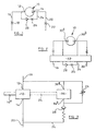
- the hydraulic motor arrangement illustrated in Figure 1 comprises a fixed displacement hydraulic motor 10 having an inlet port 12 and an outlet port 14.
- the inlet port 12 communicates through a supply passage 16 including a restriction 18 with a source of hydraulic fluid under pressure (not shown).
- the outlet port 14 communicates through a return passage 20 including a restriction 22 with an appropriate reservoir (not shown) from which the hydraulic fluid may be drawn by an appropriate pump to supply the hydraulic fluid under pressure to the passage 16 at a subsequent point in the operation of the hydraulic motor arrangement.
- a by-pass line or passage 24 is connected between the outlet port 14 and the inlet port 12, the by-pass passage 24 including a restriction 26 and a non-return valve 28 orientated to permit fluid to flow from the outlet port 14 to the inlet port 12, but to substantially prevent flow of fluid through the by-pass passage 24 in the reverse direction.
- the hydraulic motor includes an output shaft (not shown in the Figure 1 arrangement) which, in use, is connected to a load to be moved.
- the output shaft of the hydraulic motor may be connected, through appropriate gearing, with an aircraft flap or slat which is to be moved.
- hydraulic fluid under pressure is applied through the passage 16 to the inlet port 12.
- the supply of fluid under pressure to the hydraulic motor causes the motor to operate, rotating the output shaft, fluid escaping from the motor 10 through the outlet port 14 from where the fluid is returned to the fluid reservoir through the passage 20.
- the non-return valve 28 is held in its closed position, thus fluid is unable to flow along the by-pass passage 24.
- the assisting load causes operation of the motor 10, drawing fluid from the inlet port 12 and supplying fluid to the outlet port.
- the presence of the restrictions 18, 22 in the inlet and outlet passages 16, 20 result in the fluid pressure at the outlet port 14 being greater than that at the inlet port 12.
- fluid is able to flow along the by-pass passage 24, through the restriction 26 and non-return valve 28 to the inlet port 12.
- Such a flow of fluid is advantageous in that the net quantity of fluid drawn from the passage 16 by the hydraulic motor arrangement in circumstances in which such an assisting load is applied is reduced, thus the efficiency of the hydraulic motor arrangement is improved.
- the restriction 26 may be replaced, if desired, by a flow limiting valve.
- the arrangement illustrated in Figure 2 is similar to that of Figure 1, but includes a fixed displacement hydraulic motor 10 which is capable of operating in either direction.
- the hydraulic motor 10 includes first and second ports 30 a , 30 b which communicate through an appropriate control valve arrangement 32 with the supply and return passages 16, 20 and with the by-pass passage 24 such that in one mode of operation, the supply passage 16 supplies fluid to the port 30 a the port 30 b communicating with the return passage 20, and flow is permitted along the by-pass passage 24 from the port 30 b to the port 30 a , and in a second mode of operation, the supply passage 16 communicates with the port 30 b , the return passage 20 communicating with the port 30 a , the by-pass passage 24 permitting fluid flow from the port 30 a to the port 30 b , but substantially preventing fluid flow in the reverse direction.
- Such an arrangement is advantageous in that the hydraulic motor can be positively driven in both directions, and aiding or assisting loads in either direction can be used to reduce the net quantity of fluid drawn by the hydraulic motor arrangement from the source of fluid under
- the embodiment of Figure 2 uses the valve arrangement 32 to control which of the ports 30 a , 30 b acts as the inlet port and which of the ports 30 a , 30 b acts as the outlet port at any given instant.
- control valve 32 may be arranged only to control communication between the ports 30 a , 30 b and the passages 16, 20, the control valve 32 not communicating with the by-pass passage 24.
- an appropriate pressure sensitive logic arrangement may be used in the by-pass passage 24 to control the operation of valves, thereby controlling the direction of fluid flow through the passage 24.
- the arrangement illustrated in Figure 3 is designed to improve efficiency under low opposing load conditions and differs from the arrangements of Figures 1 and 2 in that the motor 10 is connected through an appropriate drive arrangement 34 with a fixed displacement pump 36 which is located in parallel with the restriction 26 in the by-pass passage 24.
- the restriction 26 takes the form of a variable flow restriction and is arranged to be controlled in such a manner as to be responsive to the magnitude of the load applied to the hydraulic motor 10.
- the pump 36 is driven by the drive arrangement 34 in such a manner as to return fluid towards the inlet port 12 of the motor 10, the pump 36 being driven at a speed associated with the operating speed of the motor 10.
- the restriction to the flow of fluid provided by the restriction 26 is controlled in such a manner as to be low.
- the application of fluid under pressure to the passage 16 and inlet port 12 drives the motor 10 to cause rotation of the output shaft 10 a , fluid being returned through the outlet port 14 and return passage 20 to the fluid reservoir.
- the restrictor 26 forms only a low restriction to fluid flow during such circumstances, the operation of the pump 36 during such operation of the hydraulic motor arrangement has little effect, any pressurization of fluid at the outlet 36 a of the pump 36 being of small magnitude as fluid is able to return to the inlet 36 b of the pump 36 through the restriction 26.
Landscapes
- Engineering & Computer Science (AREA)
- Physics & Mathematics (AREA)
- Fluid Mechanics (AREA)
- Mechanical Engineering (AREA)
- General Engineering & Computer Science (AREA)
- Chemical & Material Sciences (AREA)
- Analytical Chemistry (AREA)
- Fluid-Pressure Circuits (AREA)
- Hydraulic Motors (AREA)
Claims (7)
- Hydraulikmotoranordnung, die einen Hydraulikmotor (10) einschließt, der eine Einlaßöffnung (12), angeordnet zum Aufnehmen eines Antriebsfluids, vorzugsweise von einem Wegeventilmittel (32), mit Hilfe einer Zuflußleitung (16), und eine Auslaßöffnung (14) hat, wodurch das Fluid mit Hilfe einer Abflußleitung (20) aus dem Motor austreten kann, wobei eine Ausweichleitung (24) die Einlaß- und die Auslaßöffnung miteinander verbindet und die Anordnung gekennzeichnet ist durch von dem Wegeventilmittel (32), falls es bereitgestellt wird, gesonderte Drosselkörper (18, 22) in der Zufluß- bzw. der Abflußleitung (16, 20) und ein Rückschlagventil (28), das innerhalb der Ausweichleitung (24) angebracht und so angeordnet wird, daß es einen Fluidstrom von der Auslaßöffnung (14) zur Einlaßöffnung (12) ermöglicht, aber einen Fluidstrom in der umgekehrten Richtung wesentlich verhindert.
- Anordnung nach Anspruch 1, dadurch gekennzeichnet, daß der Hydraulikmotor (10) vom Zweiwegtyp ist und das Wegeventilmittel (32) bereitgestellt wird, um zu steuern, welche der Öffnungen des Motors zu einem gegebenen Zeitpunkt als Einlaßöffnung verwendet wird und welche der Öffnungen des Motors als Auslaßöffnung verwendet wird.
- Anordnung nach Anspruch 2, dadurch gekennzeichnet, daß das Wegeventilmittel (32) ebenfalls die entsprechende Richtung des Rückschlagventils (28) im Verhältnis zu den Motoröffnungen aufrechterhält.
- Anordnung nach einem der Ansprüche 1 bis 3, gekennzeichnet durch eine in der Ausweichleitung bereitgestellte Drossel (26).
- Anordnung nach Anspruch 4, dadurch gekennzeichnet, daß die Drossel (26) eine verstellbare Drossel ist.
- Anordnung nach Anspruch 5, gekennzeichnet durch eine parallel zu der verstellbaren Drossel (26) geschaltete Pumpe (36), wobei die Pumpe mit einer mit der Betriebsgeschwindigkeit des Motors (10) verbundenen Geschwindigkeit angetrieben und so angeordnet wird, daß sie das Fluid zur Einlaßöffnung (12) des Motors hin zurückführt.
- Anordnung nach Anspruch 6, dadurch gekennzeichnet, daß die verstellbare Drossel (26) auf eine solche Weise geregelt wird, daß sie auf die auf den Motor (10) ausgeübte Belastung anspricht, um unter Bedingungen niedriger Gegenbelastung eine hohe Drosselung des Stroms zu gewährleisten, so daß die Pumpe (32) einen beträchtlichen Teil des durch den Motor (10) hindurchgehenden Fluids wieder zur Motoreinlaßöffnung (12) zurückführt.
Applications Claiming Priority (2)
| Application Number | Priority Date | Filing Date | Title |
|---|---|---|---|
| GBGB9820775.6A GB9820775D0 (en) | 1998-09-25 | 1998-09-25 | Hydraulic motor |
| GB9820775 | 1998-09-25 |
Publications (3)
| Publication Number | Publication Date |
|---|---|
| EP0989308A2 EP0989308A2 (de) | 2000-03-29 |
| EP0989308A3 EP0989308A3 (de) | 2001-03-07 |
| EP0989308B1 true EP0989308B1 (de) | 2004-12-08 |
Family
ID=10839372
Family Applications (1)
| Application Number | Title | Priority Date | Filing Date |
|---|---|---|---|
| EP99307427A Expired - Lifetime EP0989308B1 (de) | 1998-09-25 | 1999-09-20 | Hydraulischer Motor |
Country Status (4)
| Country | Link |
|---|---|
| US (1) | US6345501B1 (de) |
| EP (1) | EP0989308B1 (de) |
| DE (1) | DE69922461T2 (de) |
| GB (1) | GB9820775D0 (de) |
Families Citing this family (5)
| Publication number | Priority date | Publication date | Assignee | Title |
|---|---|---|---|---|
| AU2002234067A1 (en) * | 2001-01-05 | 2002-07-16 | Ingersoll-Rand Company | Hydraulic valve system |
| US7373222B1 (en) * | 2003-09-29 | 2008-05-13 | Rockwell Automation Technologies, Inc. | Decentralized energy demand management |
| US8469677B1 (en) * | 2007-10-01 | 2013-06-25 | Sauer-Danfoss Inc. | Check valve pump with electric bypass valve |
| US20150033720A1 (en) * | 2013-08-05 | 2015-02-05 | Caterpillar Inc. | Hydraulic Motor Drive System and Method |
| US12404014B2 (en) * | 2023-03-21 | 2025-09-02 | Goodrich Corporation | Hydraulic motor start assist |
Family Cites Families (10)
| Publication number | Priority date | Publication date | Assignee | Title |
|---|---|---|---|---|
| US3785157A (en) * | 1972-11-24 | 1974-01-15 | Deere & Co | Flow control dump valve |
| JPS5379171A (en) * | 1976-12-24 | 1978-07-13 | Japan Steel Works Ltd:The | Turning drive oil-pressure circuit of construction machine |
| US4694649A (en) * | 1983-02-04 | 1987-09-22 | Howeth David F | Pressure limiting acceleration control system and valve for hydraulic motors |
| US4653271A (en) * | 1984-09-27 | 1987-03-31 | Armco Inc. | Boom crane centering |
| US4782662A (en) * | 1984-09-27 | 1988-11-08 | National-Oilwell | Boom crane centering |
| US4586332A (en) * | 1984-11-19 | 1986-05-06 | Caterpillar Tractor Co. | Hydraulic swing motor control circuit |
| US5410842A (en) * | 1993-11-12 | 1995-05-02 | Asi Technologies, Inc. | Two speed hydraulic door operator |
| US5596872A (en) * | 1994-10-17 | 1997-01-28 | Payne; William H. | Hydro-mechanical power transmission |
| JPH0972303A (ja) * | 1995-09-06 | 1997-03-18 | Tokimec Inc | 可変容量形液圧装置システム |
| JPH10246205A (ja) * | 1997-03-05 | 1998-09-14 | Shin Caterpillar Mitsubishi Ltd | 油圧モータの油圧制御回路装置 |
-
1998
- 1998-09-25 GB GBGB9820775.6A patent/GB9820775D0/en not_active Ceased
-
1999
- 1999-09-20 EP EP99307427A patent/EP0989308B1/de not_active Expired - Lifetime
- 1999-09-20 DE DE69922461T patent/DE69922461T2/de not_active Expired - Lifetime
- 1999-09-24 US US09/405,415 patent/US6345501B1/en not_active Expired - Lifetime
Also Published As
| Publication number | Publication date |
|---|---|
| EP0989308A2 (de) | 2000-03-29 |
| DE69922461D1 (de) | 2005-01-13 |
| EP0989308A3 (de) | 2001-03-07 |
| GB9820775D0 (en) | 1998-11-18 |
| DE69922461T2 (de) | 2005-12-15 |
| US6345501B1 (en) | 2002-02-12 |
Similar Documents
| Publication | Publication Date | Title |
|---|---|---|
| US5329767A (en) | Hydraulic circuit flow control | |
| US5287794A (en) | Hydraulic motor with inlet fluid supplemented by fluid from contracting chamber | |
| US5293745A (en) | Fluid power regenerator | |
| CN104520594B (zh) | 具有力调制的无计量液压系统 | |
| US4768340A (en) | Automatic displacement control for variable displacement motor | |
| GB1373902A (en) | Hydraulic system for a vehicle having a steering system and air conditioning unit | |
| EP0989308B1 (de) | Hydraulischer Motor | |
| US8919114B2 (en) | Closed-loop hydraulic system having priority-based sharing | |
| JPH1047304A (ja) | 液圧的な駆動機構 | |
| US4579039A (en) | Power drive unit | |
| US3391537A (en) | Fluid system for independent operation of two fluid motors | |
| US6298661B1 (en) | Energy efficient hydraulic motor control system | |
| US6122913A (en) | Drive for a mobile operating device | |
| US4762195A (en) | Hydraulic steering system | |
| US5634527A (en) | Speed responsive power steering | |
| JPS6035562B2 (ja) | 液圧制御装置 | |
| US20040177610A1 (en) | Broad range speed control for hydraulic motors | |
| US4989495A (en) | Hydraulic positioning system with normal and high supply and exhaust flow paths | |
| US20030121258A1 (en) | Hydraulic control system for reducing motor cavitation | |
| JPH0260882B2 (de) | ||
| US4748891A (en) | Hydraulic system | |
| JPH04131568A (ja) | 油圧伝達装置 | |
| JPS6227275B2 (de) | ||
| JPS59175671A (ja) | 可変容量型液圧モ−タの制御回路 | |
| SU1105340A1 (ru) | Гидроходопреобразователь транспортного средства |
Legal Events
| Date | Code | Title | Description |
|---|---|---|---|
| PUAI | Public reference made under article 153(3) epc to a published international application that has entered the european phase |
Free format text: ORIGINAL CODE: 0009012 |
|
| AK | Designated contracting states |
Kind code of ref document: A2 Designated state(s): DE ES FR GB IT |
|
| AX | Request for extension of the european patent |
Free format text: AL;LT;LV;MK;RO;SI |
|
| PUAL | Search report despatched |
Free format text: ORIGINAL CODE: 0009013 |
|
| AK | Designated contracting states |
Kind code of ref document: A3 Designated state(s): AT BE CH CY DE DK ES FI FR GB GR IE IT LI LU MC NL PT SE |
|
| AX | Request for extension of the european patent |
Free format text: AL;LT;LV;MK;RO;SI |
|
| RIC1 | Information provided on ipc code assigned before grant |
Free format text: 7F 15B 21/14 A, 7F 15B 11/024 B |
|
| 17P | Request for examination filed |
Effective date: 20010814 |
|
| AKX | Designation fees paid |
Free format text: DE ES FR GB IT |
|
| RAP1 | Party data changed (applicant data changed or rights of an application transferred) |
Owner name: LUCAS INDUSTRIES LIMITED |
|
| 17Q | First examination report despatched |
Effective date: 20030513 |
|
| RAP1 | Party data changed (applicant data changed or rights of an application transferred) |
Owner name: GOODRICH ACTUATION SYSTEMS LTD |
|
| GRAP | Despatch of communication of intention to grant a patent |
Free format text: ORIGINAL CODE: EPIDOSNIGR1 |
|
| GRAS | Grant fee paid |
Free format text: ORIGINAL CODE: EPIDOSNIGR3 |
|
| GRAA | (expected) grant |
Free format text: ORIGINAL CODE: 0009210 |
|
| AK | Designated contracting states |
Kind code of ref document: B1 Designated state(s): DE ES FR GB IT |
|
| PG25 | Lapsed in a contracting state [announced via postgrant information from national office to epo] |
Ref country code: IT Free format text: LAPSE BECAUSE OF FAILURE TO SUBMIT A TRANSLATION OF THE DESCRIPTION OR TO PAY THE FEE WITHIN THE PRESCRIBED TIME-LIMIT;WARNING: LAPSES OF ITALIAN PATENTS WITH EFFECTIVE DATE BEFORE 2007 MAY HAVE OCCURRED AT ANY TIME BEFORE 2007. THE CORRECT EFFECTIVE DATE MAY BE DIFFERENT FROM THE ONE RECORDED. Effective date: 20041208 |
|
| REG | Reference to a national code |
Ref country code: GB Ref legal event code: FG4D |
|
| REF | Corresponds to: |
Ref document number: 69922461 Country of ref document: DE Date of ref document: 20050113 Kind code of ref document: P |
|
| PG25 | Lapsed in a contracting state [announced via postgrant information from national office to epo] |
Ref country code: ES Free format text: LAPSE BECAUSE OF FAILURE TO SUBMIT A TRANSLATION OF THE DESCRIPTION OR TO PAY THE FEE WITHIN THE PRESCRIBED TIME-LIMIT Effective date: 20050319 |
|
| PLBE | No opposition filed within time limit |
Free format text: ORIGINAL CODE: 0009261 |
|
| STAA | Information on the status of an ep patent application or granted ep patent |
Free format text: STATUS: NO OPPOSITION FILED WITHIN TIME LIMIT |
|
| 26N | No opposition filed |
Effective date: 20050909 |
|
| ET | Fr: translation filed | ||
| REG | Reference to a national code |
Ref country code: FR Ref legal event code: PLFP Year of fee payment: 17 |
|
| PGFP | Annual fee paid to national office [announced via postgrant information from national office to epo] |
Ref country code: GB Payment date: 20150825 Year of fee payment: 17 Ref country code: DE Payment date: 20150820 Year of fee payment: 17 |
|
| PGFP | Annual fee paid to national office [announced via postgrant information from national office to epo] |
Ref country code: FR Payment date: 20150824 Year of fee payment: 17 |
|
| REG | Reference to a national code |
Ref country code: DE Ref legal event code: R119 Ref document number: 69922461 Country of ref document: DE |
|
| GBPC | Gb: european patent ceased through non-payment of renewal fee |
Effective date: 20160920 |
|
| REG | Reference to a national code |
Ref country code: FR Ref legal event code: ST Effective date: 20170531 |
|
| PG25 | Lapsed in a contracting state [announced via postgrant information from national office to epo] |
Ref country code: FR Free format text: LAPSE BECAUSE OF NON-PAYMENT OF DUE FEES Effective date: 20160930 Ref country code: DE Free format text: LAPSE BECAUSE OF NON-PAYMENT OF DUE FEES Effective date: 20170401 Ref country code: GB Free format text: LAPSE BECAUSE OF NON-PAYMENT OF DUE FEES Effective date: 20160920 |