EP0989356A1 - Vorrichtung zur Beleuchtung einer Fläche in mehrfache Richtungen in konzentrieter Weise - Google Patents
Vorrichtung zur Beleuchtung einer Fläche in mehrfache Richtungen in konzentrieter Weise Download PDFInfo
- Publication number
- EP0989356A1 EP0989356A1 EP99118796A EP99118796A EP0989356A1 EP 0989356 A1 EP0989356 A1 EP 0989356A1 EP 99118796 A EP99118796 A EP 99118796A EP 99118796 A EP99118796 A EP 99118796A EP 0989356 A1 EP0989356 A1 EP 0989356A1
- Authority
- EP
- European Patent Office
- Prior art keywords
- light
- surface illuminant
- optical element
- prisms
- luminance
- Prior art date
- Legal status (The legal status is an assumption and is not a legal conclusion. Google has not performed a legal analysis and makes no representation as to the accuracy of the status listed.)
- Withdrawn
Links
- 230000003287 optical effect Effects 0.000 claims abstract description 86
- 238000009826 distribution Methods 0.000 abstract description 30
- 230000007423 decrease Effects 0.000 abstract description 6
- 230000000694 effects Effects 0.000 description 10
- 239000004973 liquid crystal related substance Substances 0.000 description 6
- NCGICGYLBXGBGN-UHFFFAOYSA-N 3-morpholin-4-yl-1-oxa-3-azonia-2-azanidacyclopent-3-en-5-imine;hydrochloride Chemical compound Cl.[N-]1OC(=N)C=[N+]1N1CCOCC1 NCGICGYLBXGBGN-UHFFFAOYSA-N 0.000 description 4
- 230000008859 change Effects 0.000 description 4
- 238000007796 conventional method Methods 0.000 description 2
- 239000000463 material Substances 0.000 description 2
- 238000000034 method Methods 0.000 description 2
- 230000008569 process Effects 0.000 description 2
- 239000004925 Acrylic resin Substances 0.000 description 1
- 229920000178 Acrylic resin Polymers 0.000 description 1
- NIXOWILDQLNWCW-UHFFFAOYSA-N acrylic acid group Chemical group C(C=C)(=O)O NIXOWILDQLNWCW-UHFFFAOYSA-N 0.000 description 1
- 239000011324 bead Substances 0.000 description 1
- 230000006866 deterioration Effects 0.000 description 1
- 230000001747 exhibiting effect Effects 0.000 description 1
- 238000004519 manufacturing process Methods 0.000 description 1
- 229920000515 polycarbonate Polymers 0.000 description 1
- 239000004417 polycarbonate Substances 0.000 description 1
- 229920000728 polyester Polymers 0.000 description 1
- 229920001225 polyester resin Polymers 0.000 description 1
- 239000004645 polyester resin Substances 0.000 description 1
- 239000011347 resin Substances 0.000 description 1
- 229920005989 resin Polymers 0.000 description 1
Images


Classifications
-
- G—PHYSICS
- G02—OPTICS
- G02B—OPTICAL ELEMENTS, SYSTEMS OR APPARATUS
- G02B6/00—Light guides; Structural details of arrangements comprising light guides and other optical elements, e.g. couplings
- G02B6/0001—Light guides; Structural details of arrangements comprising light guides and other optical elements, e.g. couplings specially adapted for lighting devices or systems
- G02B6/0011—Light guides; Structural details of arrangements comprising light guides and other optical elements, e.g. couplings specially adapted for lighting devices or systems the light guides being planar or of plate-like form
- G02B6/0033—Means for improving the coupling-out of light from the light guide
- G02B6/005—Means for improving the coupling-out of light from the light guide provided by one optical element, or plurality thereof, placed on the light output side of the light guide
- G02B6/0053—Prismatic sheet or layer; Brightness enhancement element, sheet or layer
Definitions
- the present invention relates to a surface illuminant device which can be used as a backlight of a liquid crystal display device or the like.
- a conventional backlight of a liquid crystal display device or the like generally employs an edge light system.
- a cold cathode fluorescent tube is used as light source and placed on a side (edge) of a light guide plate, an optical sheet is placed on a surface of the light guide plate from which light is emitted (light emission surface), and a reflecting material is placed on the bottom side of the light guide plate (the side opposed to the light emission surface).
- Efforts have been made to improve efficiency in use of light and accordingly enhance luminance by adjusting the shape of the light guide plate as well as the shape and type of the optical sheet. Further, efforts have been made to emit the light from the light emission surface in all directions as uniformly as possible.
- Japanese Patent Laying-Open No. 8-262441 discloses a surface illuminant element which emits light in the direction of normal line in concentrative manner by the structure constituted of a light source having directivity in two specific directions and a prism sheet arranged such that the apical angle of a prism faces downward.
- Japanese Patent Laying-Open No. 8-262442 discloses a surface illuminant element which emits light just in a desired direction in concentrative manner by employing the structure similar to that disclosed in Japanese Patent Laying Open No. 8-262441.
- the conventional technique is employed in the car navigation, for example, in which the liquid crystal display device is located at the central portion of the car and persons in the driver's seat and the passenger seat watch the display device from two specific directions, a relatively large amount of light is emitted in directions other than the watching directions and thus improvements in the efficiency in use of the light are demanded in the conventional technique.
- One object of the present invention is to provide a surface illuminant device to emit light in a plurality of directions in concentrative manner and accordingly enhance luminance in the plurality of directions.
- Another object of the present invention is to provide a surface illuminant device to emit light in two specific directions in concentrative manner and accordingly enhance luminance in the two specific directions.
- Still another object of the present invention is to provide a surface illuminant device which has a luminance distribution (light distribution characteristic) with a gentle decrease in luminance in the vicinity of the direction in which the light is emitted in concentrative manner.
- the surface illuminant device includes a surface illuminant which does not allow light to be emitted in a specific direction and a first optical element which has a plurality of prisms each having a predetermined apical angle.
- the first optical element is arranged on a light emission side (the side from which light is emitted) of the surface illuminant.
- the first optical element has one side and the other side opposite to the one side and the plurality of prisms are placed on the one side of the first optical element.
- the one side of the first optical element on which the plurality of prisms are placed is opposite to the light emission side of the surface illuminant.
- the predetermined apical angle is 60° to 94°.
- the plurality of prisms are a plurality of linear prisms elongating in a first direction each having a substantially triangular cross section, and they are arranged with their respective apical angles facing in a second direction which crosses the first direction.
- the plurality of prisms are arranged in a third direction which crosses the first and the second direction.
- the plurality of prisms are a plurality of linear prisms elongating in a first direction having a wave-shaped cross section, and they are arranged with respective apical angles facing in a second direction which crosses the first direction.
- the plurality of prisms are arranged in a third direction which crosses the first and the second direction.
- the surface illuminant device further includes a second optical element which condenses incident light.
- the second optical element is arranged on a light emission side of the first optical element.
- a surface illuminant device can be provided which emits light in a plurality of specific directions in concentrative manner to enhance luminance in the plurality of specific directions. Further, a surface illuminant device can be provided which emits light in two specific directions in concentrative manner to enhance luminance in the two specific directions. In addition, a surface illuminant device can be provided which has a luminance distribution (light distribution characteristic) with a gentle decrease in luminance in the vicinity of the direction in which light is emitted in concentrative manner.
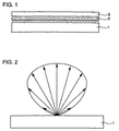
- the surface illuminant device of the present invention is constructed of a surface illuminant 1 and optical elements P and S.
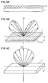
- Surface illuminant 1 is a light source which has a luminance characteristic as shown in Fig. 2.
- Optical element P functions to direct emitted light in two particular directions.
- Optical element S functions to condense the emitted light.
- Surface illuminant 1 and optical elements P and S are combined to constitute the surface illuminant device which has a luminance distribution (light distribution characteristic) where light is directed in two desired directions and the luminance gentry decreases in the vicinity of the two desired directions.
- surface illuminant 1 having the luminance characteristic as illustrated in Fig. 2 is structured as shown in Figs. 3A and 3B.
- a fluorescent tube 12 having a 90° inverted U shape is placed to surround the side and edge portions of a light guide plate 11 formed of transparent acrylic resin.
- Light guide plate 11 is 76.5 mm in length, 131.4 mm in width, and 4 mm in thickness.
- the outer diameter of fluorescent tube 12 is 2.6 mm.
- Satin finish is applied to the back surface of light guide plate 11.
- a diffuse reflection sheet 13 is placed on the satin-finished back surface of light guide plate 11.
- a relation between an angle of light to the line which is normal to the surface of light guide plate 11 of surface illuminant 1 and a relative luminance of the light is illustrated in Fig. 4.
- a distribution characteristic is shown which has a small variation in luminance throughout a wide viewing angle.
- fluorescent tube 12 having 90° inverted U shape is herein used, a linear fluorescent tube may be employed.
- any two-dimensional light source is applicable if it has the light distribution characteristic as shown in Fig. 2.
- Optical element P is shaped like a sheet and formed of a number of linear prisms each having an apical angle of 90° which is located on the side of the plane of incidence.
- the prism is a triangular prism having a cross section in the shape of a right triangle.
- the total thickness of the sheet is 160 ⁇ m
- triangular prisms each having an apical angle of 90° are linearly arranged on a base of polyester layer having a thickness of 132 ⁇ m. There is no change in optical characteristics if the apical angle is in a range of 90° ⁇ 4°.
- ⁇ 4° is determined by considering the allowance on fabrication of the prisms and assembly of the surface illuminant device.
- the prism portion is made of acrylic-based resin, 28 ⁇ m in thickness, and the pitch of prisms is 50 ⁇ m.
- a curving process is applied to the prism apex to give a curve of radius 8 ⁇ m.
- mat process is applied to the light emission surface.
- a liquid crystal display device is applied to car navigation, for example, and placed between the driver's seat and the passenger seat.
- a desired condition of the apical angle of the prism is 90°. If the apical angle ranges from 60° to 94°, the light can be directed in two directions according to use.
- optical path through optical element P is described next in conjunction with Figs. 6 to 8.
- Figs. 6 to 8 there are generally three types of optical paths as listed below, through which light is emitted from a light emission surface c of optical element P.
- a luminance distribution of the light emitted from emission surface c of optical element P relative to angle is calculated for the case in which light is emitted from the surface illuminant having the luminance distribution relative to angle as shown in Fig. 4 and enters optical element P.
- an angle of light emitted from emission surface c of optical element P to the line normal to emission surface c ( ⁇ 1) is calculated as shown below.
- ⁇ represents an angle of the inclined plane of the prism to the line normal to an emission surface a of surface illuminant 1
- ⁇ 1 to ⁇ 3 represent an angle of the line normal to the inclined plane of the prism or the line normal to emission surface c to light ray
- ⁇ 1 represents an angle of the line normal to emission surface a to light ray.
- the angle ⁇ 2 of the light emitted from emission surface c of optical element P to the line normal to emission surface c is calculated as below.
- ⁇ represents an angle of the inclined plane of the prism to the line normal to emission surface a of surface illuminant 1
- ⁇ 4 to ⁇ 7 represent an angle of the line normal to the inclined plane of the prism or the line normal to emission surface c to light ray
- ⁇ 2 represents an angle of the line normal to emission surface a to light ray.
- the angle ⁇ 3 of the light emitted from emission surface c of optical element P to the line normal to emission surface c is calculated as below.
- ⁇ represents an angle of the inclined plane of the prism to the line normal to emission surface a of surface illuminant 1
- ⁇ 8 to ⁇ 10 represent an angle of the line normal to the inclined plane of the prism or the line normal to emission surface c to light ray
- ⁇ 3 represents an angle of the line normal to emission surface a to light ray.
- equations 1 to 3 are derived.
- the apical angle of the prism is defined as 90° and refractive index n of optical element P relative to the air is defined as 1.5 though the refractive index differs depending on the material used.
- the critical angle of reflection when the light is emitted into air is about 42°. ⁇ 10 in Fig. 8 is greater than the critical angle of reflection, and accordingly the light as illustrated in Fig. 8 is not emitted. Therefore, equation 3 is unnecessary.
- optical element P is arranged on surface illuminant 1, where L3 represents the direction of the edge of the linear prisms of optical element P, L1 represents a line which lies on planes of surface illuminant 1 and optical element P to form an angle of 90° to the edge direction L3 of the prism, and L2 represents a line normal to the planes of surface illuminant 1 and optical element P.
- surface illuminant 1 having the structure as shown in Figs. 3A and 3B is employed here as a specific example of the surface illuminant, any structure may be used if it provides the luminance distribution as illustrated in Fig. 2.
- the positional relation between the fluorescent tube and the edge direction L3 of the prism does not matter.
- the light emitted from surface illuminant 1 exhibits the distribution as illustrated in Fig. 4.
- the light is emitted from surface illuminant 1 exhibiting distribution as shown in Fig. 4, and then emitted from emission surface c of optical element P.
- the result of calculation is shown in Fig. 10.
- the calculation of the luminance distribution is made by dividing the light emitted from surface illuminant 1 into tiny components, calculating the angle of light emitted from emission surface c for each component using equations 1 and 2, and integrating intensifies corresponding to respective angles for the entire range of the light emitted from surface illuminant 1.
- the surface illuminant device is herein supposed to be applied to car navigation. It is confirmed that light is directed such that the luminance peak of the light is in the vicinity of the angles of approximately ⁇ 30° corresponding to the directions of the driver's seat and the passenger seat respectively. Thus it is possible to provide a surface illuminant device which can direct the emitted light in two specific directions using optical element P.
- the surface illuminant device constructed of surface illuminant 1 and optical element P can direct the light in two specific directions, the luminance drastically decreases when the viewing angle slightly shifts leading to deterioration in display characteristics. It is noted that the display is also viewed head-on and viewed from the rear seat, not just from the driver's seat and the passenger seat. An issue to be improved is that the luminance considerably deteriorates in the direction normal to the display, leading to poor view if the display is watched head-on or from the rear seat.
- optical element S is provided on surface illuminant 1 and optical element P as shown in Fig. 1.
- the prism sheet having a number of linear prism units each having an apical angle of 90° and formed at the plane of incidence is used as optical element P
- the optical sheet having a function of condensing diffused light is used as optical element S.
- an optical sheet of model number D121 by Tsujiden Co., Ltd. is employed.
- a number of beads having condensing effect are dispersed in optical element S.
- the sheet is made of polyester resin and has a thickness of approximately 130 to 140 ⁇ m.
- the condensing effect of optical element S is described now.
- the condensing effect of optical element S is represented by an expression X1/X0.
- a main axis of light distribution before the light enters optical element S is at about 40°
- a main axis of light distribution for the light emitted from optical element S is at about 30°.
- the angle to be attained is approximately 30° and an allowable range thereof is 30° ⁇ 5°
- the condensing effect of optical element S ranges from about 1.2 to 1.8.
- optical element S may be a cylindrical lens array, a convex lens, or a micro lens array.
- the required optical condition is just to satisfy the condensing effect described above.
- optical element S has the condensing effect relative to the direction normal to the emission surface.
- Figs. 15 and 16 illustrating the luminance distributions relative to angle in the first embodiment, it can be confirmed that the luminance is relatively high in certain two specific directions and the luminance gently changes in the vicinity of those directions.
- the surface illuminant device is applied to a liquid crystal display device for car navigation placed between the driver's seat and the passenger seat, the display screen seems to be bright and thus exhibits excellent display characteristics in the directions of the driver's seat and the passenger seat. Even if the viewing angle slightly shifts from the directions of the driver's and passenger seats, there is a relatively small change in luminance and thus superior display characteristics can be obtained.
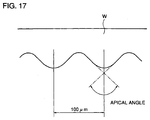
- the surface illuminant device in the second embodiment employs, instead of optical element P formed of linear prisms, an optical element W having a wave-like cross section at its incident surface as shown in Fig. 17.
- the difference between the surface illuminant devices in the first and second embodiments is just that the former has the prism-shaped optical element P while the latter has the wave-shaped optical element W.
- Other structures of the surface illuminant device in the second embodiment are similar to those in the first embodiment, and description thereof is not repeated here.
- the second embodiment is also supposed to be applied to car navigation. As shown in Fig. 18, it is confirmed that the surface illuminant device in the second embodiment directs light such that the peak of luminance is at angles of approximately ⁇ 30° corresponding to the driver's seat and the passenger seat respectively.
- the surface illuminant device using wave-shaped optical element W thus allows the emitted light to be directed in two specific directions.
- Fig. 18 Distribution of the luminance of light emitted from surface illuminant 1 relative to the angle is shown in Fig. 18.
- the light condensing effect of optical element S also ranges from about 1.2 to 1.8 as in the first embodiment.
- optical element W is formed like a sheet having a number of curves constituting a wave.
- the apical angle of each curve is approximately 90° at the light incident surface.
- the apical angle of the curve herein refers to the angle formed by the tangents which meet first at the inflection points, the inflection point being located at a point where the differential value of the slope of the curve changes from + to - or - to +.
- the pitch of the curves is 100 ⁇ m.
- Optical element W has a total thickness of approximately 200 ⁇ m and is made of polycarbonate.
- model number W818 by Sekisui Chemical Co., Ltd. is employed here.
- the apical angle thereof is 97°.
- Model number W518 by Sekisui Chemical Co., Ltd. having apical angle of 81° also exhibits the characteristics as shown in Fig. 18. (The light condensing effect of optical element S when model number W518 is used also ranges from about 1.2 to 1.8.)
- the emitted light can be directed in two specific directions as shown in Fig 18.
- the arrangement of the optical elements according to the present invention allows light to be directed efficiently at desired angles (viewing angles), so that brightness can be achieved at the desired angles (viewing angles).
- the surface illuminant device can distribute the emitted light in two specific directions and allow the luminance to gently change in the vicinity of the two specific directions. Therefore, if the surface illuminant device is applied to a liquid crystal display used for car navigation, for example, that is placed between the driver's seat and the passenger seat, the display screen seems to be bright from the driver's seat and the passenger seat and thus provide an excellent display characteristic. Even if the viewing angle slightly shifts from the direction of the driver's and passenger seats, there is no significant change in luminance and thus a fine display characteristic is obtained. In addition, even if the display is watched by a person in front of the display or in the rear seat, the luminance in the normal direction just slightly decreases and thus there is no influence on the display characteristic.
Landscapes
- Physics & Mathematics (AREA)
- General Physics & Mathematics (AREA)
- Optics & Photonics (AREA)
- Planar Illumination Modules (AREA)
- Liquid Crystal (AREA)
Applications Claiming Priority (4)
| Application Number | Priority Date | Filing Date | Title |
|---|---|---|---|
| JP26925798 | 1998-09-24 | ||
| JP26925798 | 1998-09-24 | ||
| JP11172473A JP2000164016A (ja) | 1998-09-24 | 1999-06-18 | 面光源装置 |
| JP17247399 | 1999-06-18 |
Publications (1)
| Publication Number | Publication Date |
|---|---|
| EP0989356A1 true EP0989356A1 (de) | 2000-03-29 |
Family
ID=26494815
Family Applications (1)
| Application Number | Title | Priority Date | Filing Date |
|---|---|---|---|
| EP99118796A Withdrawn EP0989356A1 (de) | 1998-09-24 | 1999-09-23 | Vorrichtung zur Beleuchtung einer Fläche in mehrfache Richtungen in konzentrieter Weise |
Country Status (3)
| Country | Link |
|---|---|
| US (1) | US6357888B1 (de) |
| EP (1) | EP0989356A1 (de) |
| JP (1) | JP2000164016A (de) |
Cited By (1)
| Publication number | Priority date | Publication date | Assignee | Title |
|---|---|---|---|---|
| CN106154395A (zh) * | 2015-05-11 | 2016-11-23 | 奇美实业股份有限公司 | 导光板、背光组件及照明装置 |
Families Citing this family (16)
| Publication number | Priority date | Publication date | Assignee | Title |
|---|---|---|---|---|
| KR100806093B1 (ko) * | 2000-04-27 | 2008-02-21 | 가부시키가이샤 구라레 | 면광원소자 및 이를 사용한 표시장치 |
| JP2002124112A (ja) * | 2000-08-07 | 2002-04-26 | Sharp Corp | バックライト及び液晶表示装置 |
| US7230764B2 (en) * | 2000-08-18 | 2007-06-12 | Reflexite Corporation | Differentially-cured materials and process for forming same |
| US20040190102A1 (en) * | 2000-08-18 | 2004-09-30 | Mullen Patrick W. | Differentially-cured materials and process for forming same |
| JP2004506547A (ja) * | 2000-08-18 | 2004-03-04 | リフレキサイト・コーポレーション | 差別的に硬化した材料およびその材料の形成方法 |
| JP4266551B2 (ja) * | 2000-12-14 | 2009-05-20 | 三菱レイヨン株式会社 | 面光源システムおよびそれに用いる光偏向素子 |
| JP4798900B2 (ja) * | 2001-08-30 | 2011-10-19 | 京セラ株式会社 | 液晶表示装置 |
| EP1625430A2 (de) * | 2003-05-02 | 2006-02-15 | Reflexite Corporation | Lichtumlenkende optische strukturen |
| US7160017B2 (en) * | 2004-06-03 | 2007-01-09 | Eastman Kodak Company | Brightness enhancement film using a linear arrangement of light concentrators |
| KR20070007648A (ko) * | 2005-07-11 | 2007-01-16 | 삼성전자주식회사 | 양방향 광전달 반투과 프리즘 시트, 양방향 백라이트어셈블리 및 이를 포함하는 양방향 액정표시장치 |
| US7310136B2 (en) * | 2005-11-23 | 2007-12-18 | General Electric Company | Method and apparatus for measuring prism characteristics |
| US7637639B2 (en) * | 2005-12-21 | 2009-12-29 | 3M Innovative Properties Company | LED emitter with radial prismatic light diverter |
| JP2007258152A (ja) * | 2006-02-24 | 2007-10-04 | Citizen Electronics Co Ltd | バックライトユニット及びそれを備えた表示装置 |
| JP2010003656A (ja) * | 2007-09-20 | 2010-01-07 | Hitachi Maxell Ltd | 照明装置、照明方法、照明システム及び表面情報取得装置 |
| JP2009110765A (ja) * | 2007-10-29 | 2009-05-21 | Omron Corp | 面光源装置及び液晶表示装置 |
| TWI490571B (zh) * | 2014-03-24 | 2015-07-01 | Chi Mei Corp | 導光板及具有其之背光模組 |
Citations (7)
| Publication number | Priority date | Publication date | Assignee | Title |
|---|---|---|---|---|
| EP0317250A2 (de) * | 1987-11-12 | 1989-05-24 | Mitsubishi Rayon Co., Ltd. | Ebene Lichtquelle |
| EP0457009A2 (de) * | 1990-05-17 | 1991-11-21 | Nissen Kagakukogyo K.K. | Lichtreflektierendes Element, Herstellungsverfahren und Verwendung |
| EP0597261A1 (de) * | 1992-10-09 | 1994-05-18 | Asahi Glass Company Ltd. | Beleuchtungsvorrichtung und Flüssigkristall-Anzeigevorrichtung |
| JPH08234203A (ja) * | 1994-12-28 | 1996-09-13 | Enplas Corp | 二光束生成方法及び二光束生成型面光源装置 |
| JPH08286629A (ja) * | 1995-04-17 | 1996-11-01 | Sekisui Chem Co Ltd | 集光シート |
| US5598280A (en) * | 1993-03-23 | 1997-01-28 | Dai Nippon Printing Co., Ltd. | Film lens and a surface light source using the same |
| EP0819970A1 (de) * | 1996-02-07 | 1998-01-21 | Nitto Jushi Kogyo Kabushiki Kaisha | Flächenhafte lichtquelle, flüssigkristallanzeigevorrichtung und asymmetrische prismenplatte |
Family Cites Families (4)
| Publication number | Priority date | Publication date | Assignee | Title |
|---|---|---|---|---|
| JPH0727136B2 (ja) | 1987-11-12 | 1995-03-29 | 三菱レイヨン株式会社 | 面光源素子 |
| JP2739731B2 (ja) | 1988-06-02 | 1998-04-15 | 三菱レイヨン株式会社 | 面光源素子 |
| JP2739730B2 (ja) | 1988-06-02 | 1998-04-15 | 三菱レイヨン株式会社 | 面光源素子 |
| JPH0727137B2 (ja) | 1988-06-02 | 1995-03-29 | 三菱レイヨン株式会社 | 面光源素子 |
-
1999
- 1999-06-18 JP JP11172473A patent/JP2000164016A/ja active Pending
- 1999-09-22 US US09/401,806 patent/US6357888B1/en not_active Expired - Lifetime
- 1999-09-23 EP EP99118796A patent/EP0989356A1/de not_active Withdrawn
Patent Citations (8)
| Publication number | Priority date | Publication date | Assignee | Title |
|---|---|---|---|---|
| EP0317250A2 (de) * | 1987-11-12 | 1989-05-24 | Mitsubishi Rayon Co., Ltd. | Ebene Lichtquelle |
| EP0457009A2 (de) * | 1990-05-17 | 1991-11-21 | Nissen Kagakukogyo K.K. | Lichtreflektierendes Element, Herstellungsverfahren und Verwendung |
| EP0597261A1 (de) * | 1992-10-09 | 1994-05-18 | Asahi Glass Company Ltd. | Beleuchtungsvorrichtung und Flüssigkristall-Anzeigevorrichtung |
| US5598280A (en) * | 1993-03-23 | 1997-01-28 | Dai Nippon Printing Co., Ltd. | Film lens and a surface light source using the same |
| JPH08234203A (ja) * | 1994-12-28 | 1996-09-13 | Enplas Corp | 二光束生成方法及び二光束生成型面光源装置 |
| US5833344A (en) * | 1994-12-28 | 1998-11-10 | Enplas Corporation | Surface light source device of dual light flux generation |
| JPH08286629A (ja) * | 1995-04-17 | 1996-11-01 | Sekisui Chem Co Ltd | 集光シート |
| EP0819970A1 (de) * | 1996-02-07 | 1998-01-21 | Nitto Jushi Kogyo Kabushiki Kaisha | Flächenhafte lichtquelle, flüssigkristallanzeigevorrichtung und asymmetrische prismenplatte |
Cited By (1)
| Publication number | Priority date | Publication date | Assignee | Title |
|---|---|---|---|---|
| CN106154395A (zh) * | 2015-05-11 | 2016-11-23 | 奇美实业股份有限公司 | 导光板、背光组件及照明装置 |
Also Published As
| Publication number | Publication date |
|---|---|
| US6357888B1 (en) | 2002-03-19 |
| JP2000164016A (ja) | 2000-06-16 |
Similar Documents
| Publication | Publication Date | Title |
|---|---|---|
| EP0989356A1 (de) | Vorrichtung zur Beleuchtung einer Fläche in mehrfache Richtungen in konzentrieter Weise | |
| US7046907B2 (en) | Backlight system | |
| JP4011287B2 (ja) | 光制御シート、面光源装置及び液晶ディスプレイ | |
| US7237930B2 (en) | Lighting system image display apparatus using the same and light diffusion plate used therefor | |
| US5608550A (en) | Front-lit liquid crystal display having brightness enhancing film with microridges which directs light through the display to a reflector | |
| US8212962B2 (en) | Optical device, material for forming optical device, backlight for display, display and method of making device or material | |
| US9404638B2 (en) | Optical element and illumination unit | |
| CN100578291C (zh) | 光线改向薄膜及薄膜系统 | |
| US20070047260A1 (en) | Brightness enhancement film using light concentrator array | |
| US7677784B2 (en) | Optical unit, backlight assembly having the same and display device having the same | |
| JP2001083330A (ja) | 導光板および平面照明装置 | |
| JP2009110765A (ja) | 面光源装置及び液晶表示装置 | |
| US6767113B2 (en) | Multi-angle reflector for use in a backlight unit | |
| US20040085750A1 (en) | Planar light source | |
| JPH0894844A (ja) | 導光板並びにこれを用いた面光源及び非発光型表示装置 | |
| US7794100B2 (en) | Planar light source apparatus, display apparatus and planar illumination method | |
| US20070285941A1 (en) | Optical Component and Backlight Unit Using the Optical Component | |
| JP2006114239A (ja) | 面状光源用導光体とその製造方法、面状光源、照明装置、看板及び液晶表示装置 | |
| JP4172008B2 (ja) | 面光源装置 | |
| JPH05203950A (ja) | 集光シートおよび面状発光装置 | |
| US20170115447A1 (en) | Prism sheet and planar illumination device | |
| US7548371B2 (en) | Optical film, illuminator and display | |
| US8491172B2 (en) | Symmetric serrated edge light guide film having elliptical base segments | |
| JPH09292531A (ja) | 導光板および光偏向板ならびに平面照明装置 | |
| JP4004599B2 (ja) | 導光板および平面照明装置 |
Legal Events
| Date | Code | Title | Description |
|---|---|---|---|
| PUAI | Public reference made under article 153(3) epc to a published international application that has entered the european phase |
Free format text: ORIGINAL CODE: 0009012 |
|
| AK | Designated contracting states |
Kind code of ref document: A1 Designated state(s): DE FR |
|
| AX | Request for extension of the european patent |
Free format text: AL;LT;LV;MK;RO;SI |
|
| 17P | Request for examination filed |
Effective date: 20000802 |
|
| AKX | Designation fees paid |
Free format text: DE FR |
|
| 17Q | First examination report despatched |
Effective date: 20060727 |
|
| 17Q | First examination report despatched |
Effective date: 20060727 |
|
| STAA | Information on the status of an ep patent application or granted ep patent |
Free format text: STATUS: THE APPLICATION IS DEEMED TO BE WITHDRAWN |
|
| 18D | Application deemed to be withdrawn |
Effective date: 20140401 |