EP0989398A2 - Vorrichtung zur Messung oder visuellen Abmusterung der Farbe oder von Farbeffekten von Oberflächen - Google Patents
Vorrichtung zur Messung oder visuellen Abmusterung der Farbe oder von Farbeffekten von Oberflächen Download PDFInfo
- Publication number
- EP0989398A2 EP0989398A2 EP99250338A EP99250338A EP0989398A2 EP 0989398 A2 EP0989398 A2 EP 0989398A2 EP 99250338 A EP99250338 A EP 99250338A EP 99250338 A EP99250338 A EP 99250338A EP 0989398 A2 EP0989398 A2 EP 0989398A2
- Authority
- EP
- European Patent Office
- Prior art keywords
- sample
- normal
- surface element
- plane
- lighting device
- Prior art date
- Legal status (The legal status is an assumption and is not a legal conclusion. Google has not performed a legal analysis and makes no representation as to the accuracy of the status listed.)
- Granted
Links
Images


Classifications
-
- G—PHYSICS
- G01—MEASURING; TESTING
- G01N—INVESTIGATING OR ANALYSING MATERIALS BY DETERMINING THEIR CHEMICAL OR PHYSICAL PROPERTIES
- G01N21/00—Investigating or analysing materials by the use of optical means, i.e. using sub-millimetre waves, infrared, visible or ultraviolet light
- G01N21/17—Systems in which incident light is modified in accordance with the properties of the material investigated
- G01N21/25—Colour; Spectral properties, i.e. comparison of effect of material on the light at two or more different wavelengths or wavelength bands
- G01N21/27—Colour; Spectral properties, i.e. comparison of effect of material on the light at two or more different wavelengths or wavelength bands using photo-electric detection ; circuits for computing concentration
- G01N21/274—Calibration, base line adjustment, drift correction
-
- G—PHYSICS
- G01—MEASURING; TESTING
- G01N—INVESTIGATING OR ANALYSING MATERIALS BY DETERMINING THEIR CHEMICAL OR PHYSICAL PROPERTIES
- G01N21/00—Investigating or analysing materials by the use of optical means, i.e. using sub-millimetre waves, infrared, visible or ultraviolet light
- G01N21/17—Systems in which incident light is modified in accordance with the properties of the material investigated
- G01N21/25—Colour; Spectral properties, i.e. comparison of effect of material on the light at two or more different wavelengths or wavelength bands
- G01N21/29—Colour; Spectral properties, i.e. comparison of effect of material on the light at two or more different wavelengths or wavelength bands using visual detection
Definitions
- the invention relates to a device for visual Sampling or alternatively to non-contact measurement of samples according to claim 1, wherein also of the Effects dependent on the direction of observation are recorded should be.
- a device for color matching known which is a concave shaped plate for receiving a sample to be sampled.
- a sample holder that is also concavely curved provided for a comparative sample, the um a common evolute of the surface of the plate and the Surface of the sample holder is pivotable.
- On the A surface lighting device is arranged for samples, whose radiating surface is convex and the with uniform and diffuse light of a given intensity the samples irradiated.
- the object of the invention is a device for Measurement or visual matching for small and medium sized flat or slightly curved samples too find the reproducible and clearly defined different observation conditions with enough enables the same lighting conditions and the under the same conditions for both a visual Sampling is also suitable for color measurements.
- one fixed observer location. Of this Location becomes a surface element on the sample, or the compilation of several samples on theirs contiguous edges considered, preferably in a basic position from the normal direction of the surface element.
- the position of the Sample is a level in which the sample is located located.
- a change in the viewing angle is effected according to the invention in that the Sample is moved in a linear direction until the desired viewing angle as the angle between Direction of observation and the normal on the sample or the surface element is reached.
- the sample will be in its home position sloping in the usual way, preferably below 45 ° illuminated. This can be done by a quasi parallel, or through a narrow beam path, e.g. with point lamps and parabolic reflectors.
- Particularly advantageous, however, and with high Correlation to outdoor lighting conditions is a ray path that is narrow only in one main plane is bundled. Such light distributions are through to generate linear light sources.
- the entire area in which the sample or parts of the sample may be at every point from the same oblique Direction illuminated. This means that the lighting conditions on the test even when postponed remain constant, creating a reproducible and Observation angle dependent matching guaranteed becomes.
- the main plane is the charisma in which the maximum concentration is reached, the level that the normal on of the sample and the line of displacement of the sample.
- the longitudinal axes of the lights or light sources run perpendicular to this main plane.
- vertical Arrangement of the sample and horizontal displacement this results in vertically aligned Shine parallel to the sample.
- vertical Arrangement of the sample, but vertical displacement there are horizontally aligned luminaires parallel to the rehearsal.
- These can be, for example be mounted on the ceiling or on the side walls.
- the lamps are used especially for visual matching selected so that their spectral distribution is predetermined Conditions, e.g. a color temperature of 6500 K and a sufficiently large metamerism index to daylight. This is determined, for example, by certain Fluorescent lamps made.
- the eye can according to the invention of the observer are replaced by sensor optics, whose optics spectrally reflect the radiance of the sample rated.
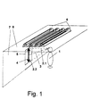
- Fig. 1 and Fig. 2 is a first arrangement of the Device for measuring and visual matching shown, which are designed as a light cabin can or can be recorded in a room.
- a vertical wall 7 and a ceiling 8 the boundary walls of the light cabin or of the room.
- On the vertical wall 7 is a vertically extended field 5 indicated that the Recording of a sample or several samples in side by side serves. Means for receiving and fastening the samples are not shown in detail, but in known way available.
- the sample is on the vertical Field 5 corresponds to the direction of displacement indicating arrow 4 can be moved up and down.
- the ceiling 8 On the ceiling 8 are parallel to the wall elongated lights 6, equipped with fluorescent lamps and appropriate reflectors attached, which are designed so that they cross in planes to the respective lamp axis, the main beam level, are closely bundled and the vertical field 5 approximately irradiate at an angle of 45 °, like by an arrow indicating the main beam direction 9 is indicated.
- Direction 3 gives one Home position from the direction of the normal, i.e. perpendicular to the sample surface, one direction 2.1 determines an angle up to 30 ° to the normal on the Sample or 15 ° of gloss and an observation direction 2.2 again gives an angle of 30 ° to the normal or 75 ° from gloss, with 0 ° from gloss direct insight into the lights via the reflective Surface of the sample means.
- the samples e.g. to be patterned Sample and reference sample attached so that the observer 1 corresponding to direction 3 as the basic position considered the samples. Then they will be accordingly moved 4 and again considered.
- the samples are postponed always from the same direction and with the same Illuminance as before from the lights 6 illuminated, which may result in errors in the matching of the sample compared to the reference sample exactly and can be reliably recognized.
- FIGS Another exemplary embodiment is shown in FIGS shown, with the samples on a horizontal extending field 5 'added and accordingly a horizontal direction of displacement 4 ' are movable.
- the sample will shift over the entire area 5 'from always the same Direction lit by the lights 6 in this Embodiment on a further side wall 8 ' Attached parallel to wall 7 and aligned vertically are.
- the main beam plane In planes transverse to the lamp axis, i.e. in horizontal plane, the main beam plane, are the Shine tightly and radiate approximately the sample at an angle of 45 °.
- the Observer 1 can be tested at different angles view, direction 3 perpendicular to the sample surface, Direction 2.2 'at an angle of up to 30 ° to the normal the sample or 75 ° of gloss, as well as the direction 2.1 ' again 30 ° to normal or 15 ° from gloss.
- an electronic one can also be used and / or electro-optical detection and measuring device be provided, directly over the color the sample is measured.
- the Lights 6 stationary on the ceiling 8 or the side wall 8 'arranged. However, you can stay the same geometric assignment with the sample or samples be moved.
Landscapes
- Physics & Mathematics (AREA)
- Spectroscopy & Molecular Physics (AREA)
- Health & Medical Sciences (AREA)
- Life Sciences & Earth Sciences (AREA)
- Chemical & Material Sciences (AREA)
- Analytical Chemistry (AREA)
- Biochemistry (AREA)
- General Health & Medical Sciences (AREA)
- General Physics & Mathematics (AREA)
- Immunology (AREA)
- Pathology (AREA)
- Engineering & Computer Science (AREA)
- Mathematical Physics (AREA)
- Theoretical Computer Science (AREA)
- Spectrometry And Color Measurement (AREA)
- Investigating Or Analysing Materials By Optical Means (AREA)
Abstract
Description
- Fig. 1
- eine perspektivische Darstellung der erfindungsgemäßen Anordnung, die als Lichtkabine realisiert sein kann, mit vertikaler Verschiebung der Probe,
- Fig. 2
- einen senkrechten Schnitt durch die Anordnung nach Fig. 1,
- Fig. 3
- eine perspektivische Darstellung der erfindungsgemäßen Anordnung mit waagerechter Verschiebung der Probe, und
- Fig. 4
- eine Draufsicht auf die Anordnung nach Fig. 3.
Claims (10)
- Vorrichtung zur Messung oder visuellen Abmusterung der Farbe oder von Farbeffekten eines ebenen oder leicht gekrümmten Oberflächenelementes als Teil der Oberfläche einer Probe, bei der die Probe mit dem Oberflächenelement in einer Ebene längs einer Graden senkrecht zur Normalen des Oberflächenelementes verschiebbar ist und das Oberflächenelement von einem festen Standort aus vor und nach der Verschiebung aus unterschiedlichen Beobachtungsrichtungen beobachtbar ist und bei der eine Beleuchtungsvorrichtung vorgesehen ist, mit der zumindest die betrachtete Teilfläche der Probe in allen durch die Verschiebungen möglichen Positionen im Wesentlichen mit gleicher Beleuchtungsstärke und aus gleicher Richtung beleuchtet wird, wobei die Lichtverteilung der Beleuchtungsvorrichtung in einer Ebene, die die Normale des Oberflächenelementes und die Verschiebegerade enthält, eine Hauptstrahlrichtung schräg zur Normalen des Oberflächenelementes besitzt.
- Vorrichtung nach Anspruch 1, dadurch gekennzeichnet, daß die Lichtverteilung eine Hauptausstrahlrichtung von 45° zur Normalen des Oberflächenelementes besitzt.
- Vorrichtung nach Anspruch 1 oder Anspruch 2, dadurch gekennzeichnet, daß eine der Beobachtungsrichtungen die Richtung senkrecht zur Normalen des Oberflächenelementes ist.
- Vorrichtung nach einem der Ansprüche 1 bis 3, dadurch gekennzeichnet, daß die Lichtverteilung der Beleuchtungsvorrichtung in der Ebene eng gebündelt ist, die die Normale des Oberflächenelementes und die Verschiebegerade enthält.
- Vorrichtung nach einem der Ansprüche 1 bis 4, dadurch gekennzeichnet, daß die Beleuchtungsvorrichtung aus mindestens einer langgestreckten Leuchte besteht, die parallel zur Ebene, in der die Probe verschoben wird, ausgerichtet ist und senkrecht die Ebene, die die Oberflächennormale und die Verschiebegerade enthält, durchstößt.
- Vorrichtung nach einem der Ansprüche 1 bis 4, dadurch gekennzeichnet, daß die Beleuchtungsvorrichtung mindestens eine Leuchte mit näherungsweise punktförmiger Lichtquelle und rotationsförmiger Lichtverteilung mit der Symmetrieachse als Hauptausstrahlrichtung aufweist.
- Vorrichtung nach einem der Ansprüche 1 bis 6, dadurch gekennzeichnet, daß die Beleuchtungsvorrichtung ortsfest ist.
- Vorrichtung nach einem der Ansprüche 1 bis 6, dadurch gekennzeichnet, daß die Beleuchtungsvorrichtung mit gleichbleibender geometrischer Zuordnung mit der Probe verschiebbar ist.
- Vorrichtung nach einem der Ansprüche 1 bis 8, dadurch gekennzeichnet, daß der Verschiebebereich der Probe so definiert ist, daß bei dem festen Standort des Beobachters alle für die Beurteilung der Proben nötigen Winkel vom Glanz zwischen 15° und 75° einstellbar sind.
- Vorrichtung nach einem der Ansprüche 1 bis 9, dadurch gekennzeichnet, daß an dem festen Standort eine elektronische und/oder Meßvorrichtung angeordnet ist, berührungslose Messung aus gleicher Richtung wie die visuelle Abmusterung durchführbar ist.
Applications Claiming Priority (2)
| Application Number | Priority Date | Filing Date | Title |
|---|---|---|---|
| DE19844053A DE19844053C2 (de) | 1998-09-25 | 1998-09-25 | Vorrrichtung zur Messung oder visuellen Abmusterung der Farbe oder von Farbeffekten auf einem Oberflächenelement |
| DE19844053 | 1998-09-25 |
Publications (3)
| Publication Number | Publication Date |
|---|---|
| EP0989398A2 true EP0989398A2 (de) | 2000-03-29 |
| EP0989398A3 EP0989398A3 (de) | 2000-05-31 |
| EP0989398B1 EP0989398B1 (de) | 2011-06-29 |
Family
ID=7882257
Family Applications (1)
| Application Number | Title | Priority Date | Filing Date |
|---|---|---|---|
| EP99250338A Expired - Lifetime EP0989398B1 (de) | 1998-09-25 | 1999-09-24 | Vorrichtung zur Messung oder visuellen Abmusterung der Farbe oder von Farbeffekten von Oberflächen |
Country Status (4)
| Country | Link |
|---|---|
| US (1) | US6437865B1 (de) |
| EP (1) | EP0989398B1 (de) |
| AT (1) | ATE514937T1 (de) |
| DE (1) | DE19844053C2 (de) |
Cited By (2)
| Publication number | Priority date | Publication date | Assignee | Title |
|---|---|---|---|---|
| DE10326217A1 (de) * | 2003-06-11 | 2004-12-30 | Bayerische Motoren Werke Ag | Verfahren zum Erkennen von Fehlern der Haftung einer Beschichtung |
| DE10326216A1 (de) * | 2003-06-11 | 2004-12-30 | Bayerische Motoren Werke Ag | Verfahren zum Erkennen von Fehlern der Haftung einer Beschichtung auf einem Substrat |
Families Citing this family (4)
| Publication number | Priority date | Publication date | Assignee | Title |
|---|---|---|---|---|
| US20040218182A1 (en) * | 2003-04-30 | 2004-11-04 | Alman David H. | Method for identifying effect pigments in a paint film for field color matching |
| US6952265B2 (en) * | 2003-06-12 | 2005-10-04 | E. I. Du Pont De Nemours And Company | Method of characterization of surface coating containing metallic flakes and device used therein |
| US7430316B2 (en) * | 2004-01-29 | 2008-09-30 | Datacolor Holding Ag | Method for visually accurately predicting color matches on different materials |
| DE102006038200A1 (de) * | 2006-08-16 | 2008-02-21 | Man Roland Druckmaschinen Ag | Leitstand einer Druckmaschine |
Citations (2)
| Publication number | Priority date | Publication date | Assignee | Title |
|---|---|---|---|---|
| US5604586A (en) | 1994-01-20 | 1997-02-18 | Heidelberger Druckmaschinen Ag | Color-matching apparatus for the visual on-light evaluation of flexible copies |
| WO1998008078A1 (de) | 1996-08-22 | 1998-02-26 | Dr. Ing. Willing Gmbh | Vorrichtung zur visuellen inspektion der oberflächenbeschaffenheit von abmusterungsflächen grösserer abmessung |
Family Cites Families (2)
| Publication number | Priority date | Publication date | Assignee | Title |
|---|---|---|---|---|
| DE3216991C2 (de) * | 1982-05-06 | 1984-08-09 | Heidelberger Druckmaschinen Ag, 6900 Heidelberg | Bogenauflage auf einem Auflagetisch |
| IT1245984B (it) * | 1991-01-31 | 1994-11-07 | Sib Siber Srl | Dispositivo elettronico per la rilevazione di tonalita' o differenziali di colore. |
-
1998
- 1998-09-25 DE DE19844053A patent/DE19844053C2/de not_active Expired - Fee Related
-
1999
- 1999-09-24 AT AT99250338T patent/ATE514937T1/de active
- 1999-09-24 US US09/406,020 patent/US6437865B1/en not_active Expired - Lifetime
- 1999-09-24 EP EP99250338A patent/EP0989398B1/de not_active Expired - Lifetime
Patent Citations (2)
| Publication number | Priority date | Publication date | Assignee | Title |
|---|---|---|---|---|
| US5604586A (en) | 1994-01-20 | 1997-02-18 | Heidelberger Druckmaschinen Ag | Color-matching apparatus for the visual on-light evaluation of flexible copies |
| WO1998008078A1 (de) | 1996-08-22 | 1998-02-26 | Dr. Ing. Willing Gmbh | Vorrichtung zur visuellen inspektion der oberflächenbeschaffenheit von abmusterungsflächen grösserer abmessung |
Cited By (3)
| Publication number | Priority date | Publication date | Assignee | Title |
|---|---|---|---|---|
| DE10326217A1 (de) * | 2003-06-11 | 2004-12-30 | Bayerische Motoren Werke Ag | Verfahren zum Erkennen von Fehlern der Haftung einer Beschichtung |
| DE10326216A1 (de) * | 2003-06-11 | 2004-12-30 | Bayerische Motoren Werke Ag | Verfahren zum Erkennen von Fehlern der Haftung einer Beschichtung auf einem Substrat |
| DE10326216B4 (de) * | 2003-06-11 | 2007-03-15 | Bayerische Motoren Werke Ag | Verfahren zum Erkennen von Fehlern der Haftung einer Beschichtung auf einem Substrat |
Also Published As
| Publication number | Publication date |
|---|---|
| ATE514937T1 (de) | 2011-07-15 |
| DE19844053C2 (de) | 2001-05-23 |
| DE19844053A1 (de) | 2000-04-27 |
| EP0989398A3 (de) | 2000-05-31 |
| EP0989398B1 (de) | 2011-06-29 |
| US6437865B1 (en) | 2002-08-20 |
Similar Documents
| Publication | Publication Date | Title |
|---|---|---|
| EP2020562B1 (de) | Wandleuchte | |
| DE3145633A1 (de) | Vorrichtung zur farbmessung | |
| DE4227468C2 (de) | Elektrische Schaltereinheit, insbesondere zur Steuerung von Klimaanlagen in Kraftfahrzeugen | |
| EP0989398A2 (de) | Vorrichtung zur Messung oder visuellen Abmusterung der Farbe oder von Farbeffekten von Oberflächen | |
| DE10036323A1 (de) | Leuchte für Fahrzeuge | |
| DE19826533C2 (de) | Vorrichtung zur Farbabmusterung und Farbmessung | |
| DE102014215481A1 (de) | Leuchte für eine Arbeitsumgebung, insbesondere zum Prüfen der Oberfläche von Werkstücken | |
| DE19839882C2 (de) | Beleuchtungsanlage zur Abmusterung von Oberflächenfehlern an lackierten Automobilkarosserien | |
| EP4139664A1 (de) | Leuchtenelement für einen prüftunnel, leuchtenband und prüftunnel | |
| DE2320937C3 (de) | Optische Vorrichtung zum Aufnehmen der Lichtabsorption in einem Objekt, das außerdem einen veränderlichen Brechungskoeffizienten aufweist | |
| DE10106032B4 (de) | Vorrichtung zur homogenen Ausleuchtung einer kleinen Fläche mit einer Ulbricht'schen Kugel | |
| AT504163A1 (de) | Anordnung und vorsatz zur prüfung von gegenständen | |
| EP0947827A1 (de) | Vorrichtung zur visuellen Inspektion von in verschiedenen Ebenen liegenden Oberflächen von Körpern | |
| EP1212605B1 (de) | Anordnung zur inspektion von matten ebenen und/oder leicht gekrümmten oberflächen | |
| EP0931255A1 (de) | Anordnung zur inspektion von matten ebenen und/oder gekrümmten oberflächen | |
| DE102015101252B4 (de) | Beleuchtungsvorrichtung, optisches Analysesystem sowie Verfahren zum Abtasten einer Oberfläche | |
| DE3511839A1 (de) | Lichtleiter zum beleuchten von geraeteanzeigen | |
| EP3474529A1 (de) | Beleuchtung für optische dokumentenerfassung | |
| EP0603703A1 (de) | Lesegerät | |
| DE102018115200B4 (de) | Verfahren und Vorrichtung zum optischen Messen einer in einem Probenröhrchen mit konischem Boden angeordneten Probe | |
| DE19633806A1 (de) | Beleuchtung eines Raumes zur visuellen Inspektion von Oberflächen | |
| DE1920404C (de) | Reflexions-Photometer zur Farbwertbestimmung an Proben | |
| EP0199944A2 (de) | Beleuchtungseinrichtung für eine Reiseuhr mit einstückigem Lichtleiter | |
| DE102019210253A1 (de) | Reflektoreinrichtung für eine optische Analyseeinrichtung und Verfahren zum Betreiben einer Reflektoreinrichtung | |
| DE29723859U1 (de) | C02-Sensorgerät, insbesondere CO2-Warngerät |
Legal Events
| Date | Code | Title | Description |
|---|---|---|---|
| PUAI | Public reference made under article 153(3) epc to a published international application that has entered the european phase |
Free format text: ORIGINAL CODE: 0009012 |
|
| AK | Designated contracting states |
Kind code of ref document: A2 Designated state(s): AT BE CH CY DE DK ES FI FR GB GR IE IT LI LU MC NL PT SE |
|
| AX | Request for extension of the european patent |
Free format text: AL;LT;LV;MK;RO;SI |
|
| PUAL | Search report despatched |
Free format text: ORIGINAL CODE: 0009013 |
|
| RIC1 | Information provided on ipc code assigned before grant |
Free format text: 7G 01N 21/86 A, 7G 01N 21/29 B, 7G 01N 21/25 B |
|
| AK | Designated contracting states |
Kind code of ref document: A3 Designated state(s): AT BE CH CY DE DK ES FI FR GB GR IE IT LI LU MC NL PT SE |
|
| AX | Request for extension of the european patent |
Free format text: AL;LT;LV;MK;RO;SI |
|
| 17P | Request for examination filed |
Effective date: 20001106 |
|
| AKX | Designation fees paid |
Free format text: AT BE CH CY DE DK ES FI FR GB GR IE IT LI LU MC NL PT SE |
|
| RAP1 | Party data changed (applicant data changed or rights of an application transferred) |
Owner name: FORCHHEIM & WILLING GMBH |
|
| 17Q | First examination report despatched |
Effective date: 20060918 |
|
| GRAP | Despatch of communication of intention to grant a patent |
Free format text: ORIGINAL CODE: EPIDOSNIGR1 |
|
| GRAC | Information related to communication of intention to grant a patent modified |
Free format text: ORIGINAL CODE: EPIDOSCIGR1 |
|
| RIC1 | Information provided on ipc code assigned before grant |
Ipc: G01N 21/27 20060101AFI20101216BHEP |
|
| GRAS | Grant fee paid |
Free format text: ORIGINAL CODE: EPIDOSNIGR3 |
|
| GRAA | (expected) grant |
Free format text: ORIGINAL CODE: 0009210 |
|
| AK | Designated contracting states |
Kind code of ref document: B1 Designated state(s): AT BE CH CY DE DK ES FI FR GB GR IE IT LI LU MC NL PT SE |
|
| REG | Reference to a national code |
Ref country code: GB Ref legal event code: FG4D Free format text: NOT ENGLISH |
|
| REG | Reference to a national code |
Ref country code: CH Ref legal event code: NV Representative=s name: TROESCH SCHEIDEGGER WERNER AG Ref country code: CH Ref legal event code: EP |
|
| REG | Reference to a national code |
Ref country code: IE Ref legal event code: FG4D Free format text: LANGUAGE OF EP DOCUMENT: GERMAN |
|
| REG | Reference to a national code |
Ref country code: DE Ref legal event code: R096 Ref document number: 59915282 Country of ref document: DE Effective date: 20110818 |
|
| REG | Reference to a national code |
Ref country code: NL Ref legal event code: VDEP Effective date: 20110629 |
|
| PG25 | Lapsed in a contracting state [announced via postgrant information from national office to epo] |
Ref country code: SE Free format text: LAPSE BECAUSE OF FAILURE TO SUBMIT A TRANSLATION OF THE DESCRIPTION OR TO PAY THE FEE WITHIN THE PRESCRIBED TIME-LIMIT Effective date: 20110629 |
|
| PG25 | Lapsed in a contracting state [announced via postgrant information from national office to epo] |
Ref country code: FI Free format text: LAPSE BECAUSE OF FAILURE TO SUBMIT A TRANSLATION OF THE DESCRIPTION OR TO PAY THE FEE WITHIN THE PRESCRIBED TIME-LIMIT Effective date: 20110629 Ref country code: GR Free format text: LAPSE BECAUSE OF FAILURE TO SUBMIT A TRANSLATION OF THE DESCRIPTION OR TO PAY THE FEE WITHIN THE PRESCRIBED TIME-LIMIT Effective date: 20110930 |
|
| REG | Reference to a national code |
Ref country code: IE Ref legal event code: FD4D |
|
| PG25 | Lapsed in a contracting state [announced via postgrant information from national office to epo] |
Ref country code: PT Free format text: LAPSE BECAUSE OF FAILURE TO SUBMIT A TRANSLATION OF THE DESCRIPTION OR TO PAY THE FEE WITHIN THE PRESCRIBED TIME-LIMIT Effective date: 20111031 Ref country code: NL Free format text: LAPSE BECAUSE OF FAILURE TO SUBMIT A TRANSLATION OF THE DESCRIPTION OR TO PAY THE FEE WITHIN THE PRESCRIBED TIME-LIMIT Effective date: 20110629 Ref country code: IE Free format text: LAPSE BECAUSE OF FAILURE TO SUBMIT A TRANSLATION OF THE DESCRIPTION OR TO PAY THE FEE WITHIN THE PRESCRIBED TIME-LIMIT Effective date: 20110629 |
|
| PG25 | Lapsed in a contracting state [announced via postgrant information from national office to epo] |
Ref country code: CY Free format text: LAPSE BECAUSE OF FAILURE TO SUBMIT A TRANSLATION OF THE DESCRIPTION OR TO PAY THE FEE WITHIN THE PRESCRIBED TIME-LIMIT Effective date: 20110629 |
|
| BERE | Be: lapsed |
Owner name: FORCHHEIM & WILLING G.M.B.H. Effective date: 20110930 |
|
| PG25 | Lapsed in a contracting state [announced via postgrant information from national office to epo] |
Ref country code: MC Free format text: LAPSE BECAUSE OF NON-PAYMENT OF DUE FEES Effective date: 20110930 |
|
| REG | Reference to a national code |
Ref country code: CH Ref legal event code: PL |
|
| PLBE | No opposition filed within time limit |
Free format text: ORIGINAL CODE: 0009261 |
|
| STAA | Information on the status of an ep patent application or granted ep patent |
Free format text: STATUS: NO OPPOSITION FILED WITHIN TIME LIMIT |
|
| GBPC | Gb: european patent ceased through non-payment of renewal fee |
Effective date: 20110929 |
|
| PG25 | Lapsed in a contracting state [announced via postgrant information from national office to epo] |
Ref country code: IT Free format text: LAPSE BECAUSE OF FAILURE TO SUBMIT A TRANSLATION OF THE DESCRIPTION OR TO PAY THE FEE WITHIN THE PRESCRIBED TIME-LIMIT Effective date: 20110629 |
|
| 26N | No opposition filed |
Effective date: 20120330 |
|
| REG | Reference to a national code |
Ref country code: FR Ref legal event code: ST Effective date: 20120531 |
|
| PG25 | Lapsed in a contracting state [announced via postgrant information from national office to epo] |
Ref country code: DK Free format text: LAPSE BECAUSE OF FAILURE TO SUBMIT A TRANSLATION OF THE DESCRIPTION OR TO PAY THE FEE WITHIN THE PRESCRIBED TIME-LIMIT Effective date: 20110629 Ref country code: BE Free format text: LAPSE BECAUSE OF NON-PAYMENT OF DUE FEES Effective date: 20110930 |
|
| PG25 | Lapsed in a contracting state [announced via postgrant information from national office to epo] |
Ref country code: CH Free format text: LAPSE BECAUSE OF NON-PAYMENT OF DUE FEES Effective date: 20110930 Ref country code: LI Free format text: LAPSE BECAUSE OF NON-PAYMENT OF DUE FEES Effective date: 20110930 |
|
| REG | Reference to a national code |
Ref country code: DE Ref legal event code: R097 Ref document number: 59915282 Country of ref document: DE Effective date: 20120330 |
|
| PG25 | Lapsed in a contracting state [announced via postgrant information from national office to epo] |
Ref country code: FR Free format text: LAPSE BECAUSE OF NON-PAYMENT OF DUE FEES Effective date: 20110930 Ref country code: GB Free format text: LAPSE BECAUSE OF NON-PAYMENT OF DUE FEES Effective date: 20110929 |
|
| REG | Reference to a national code |
Ref country code: AT Ref legal event code: MM01 Ref document number: 514937 Country of ref document: AT Kind code of ref document: T Effective date: 20110924 |
|
| PG25 | Lapsed in a contracting state [announced via postgrant information from national office to epo] |
Ref country code: AT Free format text: LAPSE BECAUSE OF NON-PAYMENT OF DUE FEES Effective date: 20110924 |
|
| PG25 | Lapsed in a contracting state [announced via postgrant information from national office to epo] |
Ref country code: ES Free format text: LAPSE BECAUSE OF FAILURE TO SUBMIT A TRANSLATION OF THE DESCRIPTION OR TO PAY THE FEE WITHIN THE PRESCRIBED TIME-LIMIT Effective date: 20111010 |
|
| PG25 | Lapsed in a contracting state [announced via postgrant information from national office to epo] |
Ref country code: LU Free format text: LAPSE BECAUSE OF NON-PAYMENT OF DUE FEES Effective date: 20110924 |
|
| PGFP | Annual fee paid to national office [announced via postgrant information from national office to epo] |
Ref country code: DE Payment date: 20180920 Year of fee payment: 20 |
|
| REG | Reference to a national code |
Ref country code: DE Ref legal event code: R071 Ref document number: 59915282 Country of ref document: DE |