EP0989432A2 - Dispositif de stockage règlable pour câbles à fibres optiques - Google Patents
Dispositif de stockage règlable pour câbles à fibres optiques Download PDFInfo
- Publication number
- EP0989432A2 EP0989432A2 EP99307548A EP99307548A EP0989432A2 EP 0989432 A2 EP0989432 A2 EP 0989432A2 EP 99307548 A EP99307548 A EP 99307548A EP 99307548 A EP99307548 A EP 99307548A EP 0989432 A2 EP0989432 A2 EP 0989432A2
- Authority
- EP
- European Patent Office
- Prior art keywords
- cable
- bracket
- storage unit
- arcuate section
- slack
- Prior art date
- Legal status (The legal status is an assumption and is not a legal conclusion. Google has not performed a legal analysis and makes no representation as to the accuracy of the status listed.)
- Withdrawn
Links
- 238000003860 storage Methods 0.000 title claims abstract description 36
- 239000000835 fiber Substances 0.000 title description 45
- 238000009434 installation Methods 0.000 claims abstract description 21
- 238000005452 bending Methods 0.000 claims abstract description 15
- 230000005540 biological transmission Effects 0.000 description 7
- 238000000034 method Methods 0.000 description 5
- RYGMFSIKBFXOCR-UHFFFAOYSA-N Copper Chemical compound [Cu] RYGMFSIKBFXOCR-UHFFFAOYSA-N 0.000 description 2
- 239000011521 glass Substances 0.000 description 2
- 238000012423 maintenance Methods 0.000 description 2
- 238000012360 testing method Methods 0.000 description 2
- 239000004677 Nylon Substances 0.000 description 1
- 238000004891 communication Methods 0.000 description 1
- 238000010276 construction Methods 0.000 description 1
- 238000005336 cracking Methods 0.000 description 1
- 238000013461 design Methods 0.000 description 1
- 238000011161 development Methods 0.000 description 1
- 230000018109 developmental process Effects 0.000 description 1
- 238000009826 distribution Methods 0.000 description 1
- 230000000694 effects Effects 0.000 description 1
- 238000005516 engineering process Methods 0.000 description 1
- 230000002452 interceptive effect Effects 0.000 description 1
- 238000004519 manufacturing process Methods 0.000 description 1
- 239000000463 material Substances 0.000 description 1
- 239000002184 metal Substances 0.000 description 1
- 229910052751 metal Inorganic materials 0.000 description 1
- 238000012986 modification Methods 0.000 description 1
- 230000004048 modification Effects 0.000 description 1
- 238000012544 monitoring process Methods 0.000 description 1
- 229920001778 nylon Polymers 0.000 description 1
- 230000005693 optoelectronics Effects 0.000 description 1
- 230000035755 proliferation Effects 0.000 description 1
- 230000005855 radiation Effects 0.000 description 1
Images


Classifications
-
- G—PHYSICS
- G02—OPTICS
- G02B—OPTICAL ELEMENTS, SYSTEMS OR APPARATUS
- G02B6/00—Light guides; Structural details of arrangements comprising light guides and other optical elements, e.g. couplings
- G02B6/46—Processes or apparatus adapted for installing or repairing optical fibres or optical cables
- G02B6/48—Overhead installation
- G02B6/483—Installation of aerial type
-
- G—PHYSICS
- G02—OPTICS
- G02B—OPTICAL ELEMENTS, SYSTEMS OR APPARATUS
- G02B6/00—Light guides; Structural details of arrangements comprising light guides and other optical elements, e.g. couplings
- G02B6/44—Mechanical structures for providing tensile strength and external protection for fibres, e.g. optical transmission cables
- G02B6/4439—Auxiliary devices
- G02B6/4457—Bobbins; Reels
Definitions
- the present invention relates generally to a support apparatus, and more particularly, to a cable storage unit and method for storing an extra length of fiber optic cable or the like when such cable is aerially installed on utility poles or other support structures.
- the present invention relates to an adjustable fiber optic strand storage unit that can be adjusted to accommodate a variety of different bend diameters of an assortment of fiber optic cable.
- fiber optic cable was installed only in long-distance, intercity networks and interoffice trunks. Today, however, such cable is being placed in the local loop feeder network. Future applications will extend fiber optic cable for distribution to the customer premises itself. In that, a proliferation of new information services is now available, or is being proposed for the office and home by local telephone companies and cable TV companies, to take advantage of the high communication capacity that fiber optic cable offers.
- Such interactive services include, for example, local area networks (LANs), educational/entertainment video, energy management, alarm monitoring and home banking.
- fiber optic cable is more fragile than copper wire or coaxial cable.
- fiber optic cable is more sensitive to pulling, bending and crushing forces. Accordingly, fiber optic cable demands more stringent installation and maintenance techniques than those media. If the cable is otherwise mishandled, portions of the cable have to be replaced because broken, crushed or kinked cables result in degraded transmission performance. The time and expense and inconvenience to customers associated with replacing or relocating aerially-installed fiber optic cable is substantial. This is due to high manpower requirements and the use of expensive equipment needed to install, test and maintain such transmission facilities. Those skilled in the art have not yet addressed the need to reduce the costs and inefficiencies associated with such activity after initial installation of fiber optic cable is completed.
- the extra length of cable is commonly stored by looping it around the outer periphery of an aerial device which is hung from a support messenger strand for the fiber optic line, or, alternatively, mounted on a transmission line pole.
- a generally U-shaped channel constituting the outer periphery of the aerial device, forms a guide for the cable along the sides and the return arc portion of the device.
- a workman bends a strand of cable around the outside periphery of the device to put it into storage.
- the most important fiber optic cable parameter is its bending radius.
- the cable When a fiber optic cable is being installed, and when it is finally in place, the cable must not be bent less than the minimum cable bending radius specified by the manufacturer.
- the issue becomes trying to accommodate the different bending radii when aerially installing different fiber optic cable.
- the type of known device mentioned above is a one piece device having a fixed bend diameter, therefore can only accommodate a limited number of bend radii of fiber optic cable. Thus, different sized devices must be available and utilized in the field.
- an object ofthe present invention to provide an adjustable fiber optic strand storage unit and method in the industry that will eliminate the need for different sized units to accommodate different bending radii of a variety of fiber optic cable.
- Another object of the present invention to provide an adjustable fiber optic strand storage unit and method in the industry that will inexpensively support and maintain an extra length of fiber optic cable slack in an aerial installation.
- Another object of the present invention is to provide such a storage unit that is adjustable to accommodate a variety of different bending radii of an assortment of fiber optic cable.
- a further object of the present invention is to provide an aerial storage unit of the type described, which can be readily molded or formed, and which preferably minimizes or eliminates electrical hazards to workmen when handling the storage unit near electrical transmission lines and other electrical problems such as lightning.
- the present invention addresses the above needs by providing an adjustable cable storage unit utilized in the aerial installation of a cable on a utility pole or other support structure whereby a predetermined extra length of cable slack is aerially stored and maintained in a generally planar loop as part of the initial installation of the cable.
- the cable storage unit is comprised of a bracket; a channel means positioned about the outer periphery of the bracket for receiving and guiding a portion of the predetermined length of cable slack which includes an arcuate section and two converging linear sections for guiding the portion of predetermined length of cable slack to and from the arcuate section.
- the storage unit further includes a means for selectively adjusting the diameter of the arcuate section to accommodate the bending radii of a variety of cables.
- the bracket may be formed from two separate opposing hermaphroditic pieces which are generally symmetrical about a longitudinal centerline of the bracket.
- the unit may further include at least one attachment means for aerially securing said bracket to a messenger cable.
- the present invention also provides an adjustable cable storage unit utilized in the aerial installation of a cable on a utility pole or other support structure whereby a predetermined extra length of cable slack is aerially stored and maintained in a generally planar loop as part of the initial installation of said cable.
- the unit includes a bracket having first and second ends; a channel means positioned about the outer periphery of the bracket for providing an essentially planar storage loop.
- the channel means includes a bottom surface, opposing side walls extending away from the bottom surface, and an open top, for receiving a portion of the predetermined extra length of cable slack between the side walls.
- the channel means further defines a generally arcuate section extending about the first end of said bracket to provide a return arc portion for the stored portion of the predetermined extra length of cable slack, and linear sections on opposite sides of the bracket.
- the linear sections converge from the ends of the arcuate section toward the second end for storing a further portion of the predetermined extra length of cable slack between the arcuate section and the second end.
- a centerline support member extends from the first and second ends of the bracket generally along a longitudinal centerline.
- a support cross member extends across the ends of the arcuate section.
- the cross member includes a means for adjusting the diameter of said arcuate section to accommodate the bending radii of a variety of cables.
- the bracket may be formed from two separate opposing hermaphroditic pieces which are generally symmetrical about a longitudinal centerline of the bracket. Each of the pieces includes a separate member which cooperate when the pieces are mated to form the cross member.
- the means for adjusting the diameter of the arcuate section may comprise an array of bolt openings through each member of the opposing pieces wherein the bolt openings are selectively aligned to adjust the diameter of the arcuate section.
- a representative adjustable fiber optic strand storage unit embodying various features the present invention, is generally indicated throughout the figures by reference character 10.
- storage unit 10 is preferably utilized in an aerial installation of fiber optic cable 11 or the like, whereby a predetermined extra length of cable slack 12 is aerially stored and maintained as part of the cable's initial installation.
- the fiber optic cable 11 typically placed in aerial installations is a single-mode, dielectric central member, non-armored loose tube type having from 4 to 144 fibers.
- storage unit 10 comprises a bracket 13 for storing and guiding a predetermined extra length of cable slack 12 and at least one attachment means 14 for aerially securing bracket 13 to a messenger cable 16, utility pole 17 or other support structure.
- bracket 13 is comprised of two separate opposing pieces 13a and 13b, discussed more fully below, which are conventionally molded from a glass reinforced Nylon or other suitable material capable of withstanding harmful sunlight radiation and a wide temperature range without cracking or breaking. Both pieces 13a and 13b are generally symmetrical about a longitudinal centerline of bracket 13 and are designed to be hermaphroditic, that is, only one mold is necessary to form both pieces 13a and 13b which cooperate to form bracket 13. Accordingly, the relatively few parts necessary to assemble bracket 13 and its simple design minimize the cost of manufacturing the invention.
- the outer periphery of bracket 13 includes a channel means 18, which may be generally U-shaped as shown throughout the figures, for receiving and guiding a portion of the predetermined extra length of cable slack 12.
- Channel means 18 has a bottom surface 19 and opposing side walls 21, 22 extending upwardly from each side thereof.
- channel means 18 is shaped to form a generally semi-circular arcuate section 18a and two opposed converging linear sections 18b, 18c.
- arcuate section 18a communicates smoothly and tangentially at its opposite ends 24, 26 with linear sections 18b and 18c, respectively.
- Linear sections 18b and 18c are positioned on opposite sides of bracket 13 and converge toward the relatively narrow entering and exiting end 25 of bracket 13 so that the entering and exiting portions of cable slack 12 are in proximate positions along side each other.
- arcuate section 18a of channel means 18 provides the return arc or loop portion of bracket 13 for the cable slack 12.
- Arcuate section 18a is constructed of an appropriate diameter to provide a bending surface for the fiber optic cable 11.
- the diameter requirements of arcuate section 18a as it relates to the minimum bending radii of fiber optic cable are well understood by those skilled in the field of fiber optic cable handing.
- bracket 13 respectively include support cross members 23a, 23b and centerline support members 27a, 27b.
- cross members 23a, 23b and centerline members 27a, 27b become generally aligned to form a single support cross member 23, which extends across the diametrically-opposed ends 24,26 of arcuate section 18a, and a single centerline support member 27, respectively.
- the storage unit 10 is preferably suspended horizontally in a conventional manner from a support messenger cable 16 using at least one attachment means 14.
- storage unit 10 utilizes two attachment means 14 which are comprised of conventional horizontal tap brackers. These brackets have flat metal bottoms which are bolted to the top side of bracket 13.
- Each cross member 23a and 23b includes an array of bolt openings, preferably three, designated as 29, 32, 33 and 34, 36, 37, respectively, for use in bolting a first attachment means 14 to the top side of bracket 13.
- each centerline member 27a and 27b include bolt openings 31a and 31b, respectively, adjacent narrow end 25 for use in bolting a second attachment means 14 to the top side of bracket 13.
- bolt openings 31a and 31b through centerline members 27a and 27b become axially aligned with one another to receive a bolt 38 for bolting a second attachment means 14 to bracket 13.
- bolt openings 29, 32, 33 on cross member 23a become axially aligned with bolt openings 34, 36, 37 on cross member 23b, respectively.
- a bolt 39 may be received in any one of the three sets of aligned openings 29-34, 32-36, or 33-37 to bolt a first attachment means 14 to bracket 13.
- Figures 1, 6 and 7 show bolt 39 through openings 32, 36.
- bracket 13 may partially opened so that a different set of bolt openings in cross members 23a and 23b become aligned, as shown in Fig. 5.
- the array of bolt openings in cross members 23a and 23b function as a means for adjusting the bend diameter of channel means 18a.
- partially opening bracket 13 to increase the bend diameter of channel means 18a causes bracket 13 to rotate about the axis of bolt openings 31a and 31b in centerline members 27a and 27b.
- Fig. 5 illustrates alignment of openings 34 and 32 in cross member 23a and 23b.
- any number of bolt openings in cross members 23a and 23b may be provided to function as a means of adjusting bracket 13. Accordingly, the adjustability of the preferred embodiment of the present invention can satisfactorily accommodate almost the entire range of fiber optic cables presently available for aerial installation, with minor variations.
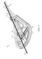
- Figs. 6 and 7 illustrate two preferred aerial installations utilizing the storage unit 10 and the methods of the present invention.
- fiber optic cable 11 originates generally from the left side of the drawing and that it has been pulled in the direction as shown by the arrow; i.e., the cable 11 has been pulled (at least initially) from left to right.
- two brackets 13 are initially attached in opposing relation to the messenger cable 16 either between utility poles 17, as shown in Fig. 6, or on opposite Sides of the utility pole 17 (not shown).
- the location of each bracket 13 along the messenger cable 16 depends upon the amount of slack desired at the location. For example, if 60 feet of slack is needed at the site, then the two brackets 13 are placed approximately 15 feet apart.
- Brackets 13 are first adjusted to accommodate the specific minimum bending radius of cable 11. The cable 11 is then drawn toward the first bracket 13 (denoted 13' in this Fig. 6). Cable 11 is then guided into the channel means 18 of the first bracket 13' starting at linear section 18b, then looping around the arcuate section 18a, and exiting toward the second bracket 13 (denoted 13" in Fig. 6) from linear section 18c of the first bracket 13'. Once cable 11 engages the first bracket 13', it is considered part of the predetermined extra length of cable slack 12.
- slack 12 can be easily installed and maintained at the minimum, bend radius, at any convenient location along the cable 11 route.
- "preferable" locations where slack may be maintained include areas where there is: clear pole space; easy entrance and exit; public area, or area accessible to splicing vehicles, tools and test equipment.
- a storage unit 10 is shown at a location where an aerial splice is located.
- a first fiber optic cable 11 (denoted 11' in Fig. 7) from the left has been spliced to a second fiber optic cable 11 (denoted 11" in Fig. 7) drawn from the right.
- a sufficient length of slack 12 is provided from the second fiber optic cable 11" so that the splicing operation can be accomplished on the ground.
- splice enclosure 28 is secured to the messenger cable 16.
- the slack 12 is then supported and maintained with a bracket 13, first into linear section 18b, around arcuate section 18a, and then exiting from linear section 18c. Excess slack 12 is pulled taut by moving bracket 13 along the messenger cable 16, at which point the apparatus is secured.
Landscapes
- Physics & Mathematics (AREA)
- General Physics & Mathematics (AREA)
- Optics & Photonics (AREA)
- Suspension Of Electric Lines Or Cables (AREA)
- Light Guides In General And Applications Therefor (AREA)
- Electric Cable Installation (AREA)
- Electric Cable Arrangement Between Relatively Moving Parts (AREA)
Applications Claiming Priority (2)
| Application Number | Priority Date | Filing Date | Title |
|---|---|---|---|
| US10159198P | 1998-09-24 | 1998-09-24 | |
| US101591P | 1998-09-24 |
Publications (2)
| Publication Number | Publication Date |
|---|---|
| EP0989432A2 true EP0989432A2 (fr) | 2000-03-29 |
| EP0989432A3 EP0989432A3 (fr) | 2002-05-02 |
Family
ID=22285443
Family Applications (1)
| Application Number | Title | Priority Date | Filing Date |
|---|---|---|---|
| EP99307548A Withdrawn EP0989432A3 (fr) | 1998-09-24 | 1999-09-24 | Dispositif de stockage règlable pour câbles à fibres optiques |
Country Status (6)
| Country | Link |
|---|---|
| US (1) | US6215937B1 (fr) |
| EP (1) | EP0989432A3 (fr) |
| JP (1) | JP2000102154A (fr) |
| BR (1) | BR9913819A (fr) |
| CA (1) | CA2283543A1 (fr) |
| PE (1) | PE20001210A1 (fr) |
Families Citing this family (17)
| Publication number | Priority date | Publication date | Assignee | Title |
|---|---|---|---|---|
| JP3338686B2 (ja) | 2000-03-07 | 2002-10-28 | 株式会社関電工 | 同軸ケーブル用ターン型取り器 |
| USD450042S1 (en) | 2001-01-26 | 2001-11-06 | Multilink, Inc. | Aerial storage unit for fiber optic cable |
| EP1649564A4 (fr) * | 2003-07-03 | 2007-09-05 | Pd Ld Inc | Utilisation de reseaux de bragg epais pour conditionnement des caracteristiques d'emission laser |
| US7085468B2 (en) * | 2004-04-22 | 2006-08-01 | Forrester Joseph H | Support fixture and method for supporting subscriber specific fiber optic drop wire |
| US20060275010A1 (en) * | 2004-04-22 | 2006-12-07 | Joseph Forrester | Support Fixture and Method for Supporting Subscriber Specific Fiber Optic Drop Wire |
| US7580607B2 (en) * | 2007-02-13 | 2009-08-25 | Preformed Line Products Company | Center-lock aerial slack cable storage bracket |
| US7627224B1 (en) | 2008-12-24 | 2009-12-01 | At&T Intellectual Property I, L.P. | Cabinet fiber manager |
| FR2943646B1 (fr) * | 2009-03-25 | 2011-07-01 | Labinal | Dispositif de stockage de sur-longueur d'une fibre optique |
| US9366836B2 (en) | 2013-09-18 | 2016-06-14 | Hubbell Incorporated | Fiber cable and drop wire organizer |
| WO2016025937A1 (fr) | 2014-08-15 | 2016-02-18 | Hubbell Incorporated | Appareil pour contenir un câble |
| US9645344B2 (en) | 2015-08-11 | 2017-05-09 | Hubbell Incorporated | Inverted cable storage device |
| WO2019209645A1 (fr) * | 2018-04-23 | 2019-10-31 | Commscope Technologies Llc | Système de support de montage de matériel de télécommunications |
| JP6939696B2 (ja) * | 2018-05-16 | 2021-09-22 | 株式会社オートネットワーク技術研究所 | ワイヤハーネス配索装置 |
| WO2021092177A1 (fr) | 2019-11-07 | 2021-05-14 | Commscope Technologies Llc | Système de montage d'enceinte de télécommunications |
| US11194110B2 (en) * | 2019-11-18 | 2021-12-07 | Afl Telecommunications Llc | Cable support devices and assemblies |
| US11703148B2 (en) * | 2020-04-17 | 2023-07-18 | Afl Telecommunications Llc | Aerial cable management device |
| WO2022032130A1 (fr) | 2020-08-07 | 2022-02-10 | Commscope Technologies Llc | Système de gestion de câble réglable |
Family Cites Families (12)
| Publication number | Priority date | Publication date | Assignee | Title |
|---|---|---|---|---|
| US4695677A (en) | 1985-06-06 | 1987-09-22 | Ruth Dale G | Wire tensioning system |
| DE3532312A1 (de) | 1985-09-11 | 1987-03-12 | Philips Patentverwaltung | Verfahren zur herstellung einer verbindung zwischen zwei optischen leitungen und anordnung zur ausuebung des verfahrens |
| US4900123A (en) | 1988-08-29 | 1990-02-13 | Gte Products Corporation | 1550 nm fiber distribution panel |
| US5013121A (en) | 1989-06-29 | 1991-05-07 | Anton Mark A | Optical fiber storage container |
| US5092663A (en) | 1990-05-21 | 1992-03-03 | Gte North Incorporated | Apparatus and method for maintaining slack of fiber optic cable or the like |
| FR2678076B1 (fr) * | 1991-06-20 | 1994-09-23 | Cit Alcatel | Module de stockage d'une reserve de support de transmission sur une liaison, notamment a fibre optique et dispositif de stockage comportant un ensemble de tels modules. |
| US5268986A (en) | 1991-09-09 | 1993-12-07 | Sumitomo Electric Industries, Ltd. | Redundant length treatment mechanism for optical fiber at terminal of optical cable |
| DE4229884C2 (de) | 1992-09-04 | 1994-06-16 | Krone Ag | Vorrichtung zur Aufbewahrung der Einzel- und Bündeladern von Glasfaserkabeln in Verteilereinrichtungen der Telekommunikations- und Datentechnik |
| US5375185A (en) | 1993-04-30 | 1994-12-20 | Keptel, Inc. | Apparatus for storing and organizing spliced optical fibers |
| US5408571A (en) | 1993-12-13 | 1995-04-18 | Multilink, Inc. | Aerial storage unit for fiber optic cable |
| US5724469A (en) * | 1996-01-26 | 1998-03-03 | Ortronics, Inc. | Adjustable fiber storage plate |
| US5867624A (en) * | 1997-07-25 | 1999-02-02 | Forrester; Joseph H. | Method and apparatus for storing surplus ADSS cable |
-
1999
- 1999-09-23 US US09/401,910 patent/US6215937B1/en not_active Expired - Lifetime
- 1999-09-24 PE PE1999000969A patent/PE20001210A1/es not_active Application Discontinuation
- 1999-09-24 EP EP99307548A patent/EP0989432A3/fr not_active Withdrawn
- 1999-09-24 CA CA002283543A patent/CA2283543A1/fr not_active Abandoned
- 1999-09-24 BR BR9913819-0A patent/BR9913819A/pt not_active IP Right Cessation
- 1999-09-24 JP JP27113099A patent/JP2000102154A/ja active Pending
Also Published As
| Publication number | Publication date |
|---|---|
| CA2283543A1 (fr) | 2000-03-24 |
| JP2000102154A (ja) | 2000-04-07 |
| BR9913819A (pt) | 2001-11-20 |
| EP0989432A3 (fr) | 2002-05-02 |
| PE20001210A1 (es) | 2000-12-24 |
| US6215937B1 (en) | 2001-04-10 |
Similar Documents
| Publication | Publication Date | Title |
|---|---|---|
| US5092663A (en) | Apparatus and method for maintaining slack of fiber optic cable or the like | |
| US6215937B1 (en) | Adjustable fiber optic strand storage unit | |
| US6278829B1 (en) | Optical fiber routing and support apparatus | |
| US5448670A (en) | Elliptical aerial self-supporting fiber optic cable and associated apparatus and methods | |
| US6668127B1 (en) | Connectorized inside fiber optic drop | |
| US6625375B1 (en) | Fiber optic interface device | |
| US6584267B1 (en) | Cable management system | |
| US5394502A (en) | Fiber optic cable harness break-out fitting | |
| US6522804B1 (en) | Connectorized outside fiber optic drop | |
| EP1446689B1 (fr) | Cables de derivation de fibres optiques | |
| US6819842B1 (en) | Aerial fiber optic system including a sub-distribution system and related methods | |
| EP1160604A2 (fr) | Système de routage et de distribution de fibres optiques | |
| US20040001686A1 (en) | Aerial closure for local convergence point | |
| EP0590018A1 (fr) | Equipement de connexion de fibres optiques | |
| US8341829B2 (en) | Taut sheath splicing apparatus | |
| US20050002623A1 (en) | Optical fibre drop cables | |
| EP2450728A1 (fr) | Plateau à fibres optiques | |
| US5823114A (en) | Utility distribution system incorporating magnetic levitation vehicle guideways | |
| EP2416196A1 (fr) | Dispositif de fixation de fibre optique | |
| CN101988979B (zh) | 用于部署在建筑墙壁上的分支光缆组件 | |
| MXPA99008782A (en) | Adjustable fiber optic cable storage unit | |
| US7313311B1 (en) | Telescoping arm with multiple fiber-optic terminals | |
| KR100355443B1 (ko) | 공중 가설 통신 케이블 | |
| KR101070456B1 (ko) | 광케이블의 배선 겸용 광단자함 고정 장치 | |
| US20240027718A1 (en) | Supporting and routing drop lines from an all-dielectric selfsupporting (adss) fiber optic trunk cable |
Legal Events
| Date | Code | Title | Description |
|---|---|---|---|
| PUAI | Public reference made under article 153(3) epc to a published international application that has entered the european phase |
Free format text: ORIGINAL CODE: 0009012 |
|
| AK | Designated contracting states |
Kind code of ref document: A2 Designated state(s): AT BE CH CY DE DK ES FI FR GB GR IE IT LI LU MC NL PT SE |
|
| AX | Request for extension of the european patent |
Free format text: AL;LT;LV;MK;RO;SI |
|
| RAP1 | Party data changed (applicant data changed or rights of an application transferred) |
Owner name: THOMAS & BETTS INTERNATIONAL, INC. |
|
| PUAL | Search report despatched |
Free format text: ORIGINAL CODE: 0009013 |
|
| RIC1 | Information provided on ipc code assigned before grant |
Free format text: 7G 02B 6/44 A, 7G 02B 6/48 B |
|
| AK | Designated contracting states |
Kind code of ref document: A3 Designated state(s): AT BE CH CY DE DK ES FI FR GB GR IE IT LI LU MC NL PT SE |
|
| AX | Request for extension of the european patent |
Free format text: AL;LT;LV;MK;RO;SI |
|
| STAA | Information on the status of an ep patent application or granted ep patent |
Free format text: STATUS: THE APPLICATION IS DEEMED TO BE WITHDRAWN |
|
| 18D | Application deemed to be withdrawn |
Effective date: 20020403 |