EP0989575A2 - Relais électromagnétique - Google Patents
Relais électromagnétique Download PDFInfo
- Publication number
- EP0989575A2 EP0989575A2 EP99116499A EP99116499A EP0989575A2 EP 0989575 A2 EP0989575 A2 EP 0989575A2 EP 99116499 A EP99116499 A EP 99116499A EP 99116499 A EP99116499 A EP 99116499A EP 0989575 A2 EP0989575 A2 EP 0989575A2
- Authority
- EP
- European Patent Office
- Prior art keywords
- section
- leaf spring
- spring
- carrier
- relay
- Prior art date
- Legal status (The legal status is an assumption and is not a legal conclusion. Google has not performed a legal analysis and makes no representation as to the accuracy of the status listed.)
- Granted
Links
Images
Classifications
-
- H—ELECTRICITY
- H01—ELECTRIC ELEMENTS
- H01H—ELECTRIC SWITCHES; RELAYS; SELECTORS; EMERGENCY PROTECTIVE DEVICES
- H01H51/00—Electromagnetic relays
- H01H51/22—Polarised relays
-
- H—ELECTRICITY
- H01—ELECTRIC ELEMENTS
- H01H—ELECTRIC SWITCHES; RELAYS; SELECTORS; EMERGENCY PROTECTIVE DEVICES
- H01H50/00—Details of electromagnetic relays
- H01H50/16—Magnetic circuit arrangements
- H01H50/18—Movable parts of magnetic circuits, e.g. armature
- H01H50/24—Parts rotatable or rockable outside coil
- H01H50/28—Parts movable due to bending of a blade spring or reed
-
- H—ELECTRICITY
- H01—ELECTRIC ELEMENTS
- H01H—ELECTRIC SWITCHES; RELAYS; SELECTORS; EMERGENCY PROTECTIVE DEVICES
- H01H50/00—Details of electromagnetic relays
- H01H50/16—Magnetic circuit arrangements
- H01H50/18—Movable parts of magnetic circuits, e.g. armature
- H01H50/30—Mechanical arrangements for preventing or damping vibration or shock, e.g. by balancing of armature
-
- H—ELECTRICITY
- H01—ELECTRIC ELEMENTS
- H01H—ELECTRIC SWITCHES; RELAYS; SELECTORS; EMERGENCY PROTECTIVE DEVICES
- H01H50/00—Details of electromagnetic relays
- H01H50/54—Contact arrangements
- H01H50/60—Contact arrangements moving contact being rigidly combined with movable part of magnetic circuit
Definitions
- the invention relates to an electromagnetic relay with a Contact arrangement and a magnet system that a yoke and has an armature movably mounted on the yoke, furthermore with a leaf spring, each with a fastening section on a flat support section of a respective rigid support formed by the yoke and / or the armature is attached flat lying and each with a subsequent unpaved spring section over a free end extends of the carrier, this spring section a predetermined range of motion perpendicular to the plane of the Fastening section has.
- Such relays are known and widely used.
- This has a leaf spring, which is connected to both the yoke and the anchor is and serves both as an armature bearing spring as also a contact spring protruding beyond the free end of the anchor forms.
- the yoke forms on which the anchor is supported, a sharp edge, and the The leaf spring lies flat on the yoke up to this edge.
- the anchor also forms at its free end a sharp edge over which the free end of the leaf spring, which carries a movable contact in the end section itself stretches flat.
- the aim of the present invention is to provide a relay of the input mentioned type constructively so that at Impact stresses a permanent deformation of the leaf spring avoided or at least greatly reduced in effect.
- this goal is achieved with a relay achieved design achieved in that between the support section and the free end of the carrier in Resting wedge-shaped rolling area for the leaf spring is formed is due to a convex curvature of a rolling section the carrier and / or the leaf spring from the plane the support section is formed away
- the leaf spring which is usually in relaxed state of the flat support section essentially extends straight over the end of the beam, Not directly on one in the area of this beam end Edge rests.
- the carrier is rather in this end area with a curved surface on which the leaf spring can roll off in the event of a shock or the leaf spring itself is concave away from the support surface at rest curved so that it is on a flat surface of the support can roll.
- the impact energy converted into an elastic deformation of the spring before the Spring reaches an edge at the end of the beam.
- About the curvature of the rolling section is that in the case of the relay necessary deformation of the spring influenced so that essentially only elastic deformations occur and plastic deformations if they are too wide Tolerance about an anchor stop occur be limited to a minimum.
- the curvature of the rolling section advantageously follows at least approximately an arc of a circle whose radius of curvature satisfies the following condition: r ⁇ d ⁇ E 2 ⁇ ⁇ FB , where r denotes the radius of curvature, d the thickness of the leaf spring, ⁇ FB the spring bending limit and E the modulus of elasticity of the leaf spring.
- the carrier preferably has the curved rolling section.
- the curvature of the rolling section can a bend of the beam may be formed. It is also next to it possible, this curvature by a one-sided embossing of the To form carrier. This is particularly beneficial if the curvature on the anchor is to be designed as a carrier. In In this case, the mass is also due to the one-sided embossing of the armature is reduced, resulting in a reduced moment of inertia has the consequence.
- a rolling section can also be used formed by a bend in the leaf spring be the result of a bias from the surface of the Getting vehicle off.
- the yoke of the relay comes in as the carrier
- the carrier is the anchor of the relay to which the Leaf spring is attached to a protruding contact spring section to form with a moving contact, so the scope for this spring section expediently limited by a stop transverse to the longitudinal direction of the anchor.
- the stop is expedient in both cases formed by molding on a base body of the relay.
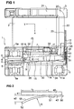
- the relay according to Figure 1 has in the usual way as Base body designed bobbin 1, the winding 2 carries between two flanges 3 and 4.
- the flange 4 is a contact arrangement with two mating contacts 5 (with connections 5a) and a movable contact 6 arranged is carried by a leaf spring 10 to be described.
- a core 7 extends axially in a manner not visible through the coil. It forms a pole plate 8 and at one end is at the opposite end with a first leg 21 connected to an angled yoke 20, the second Leg 22 is approximately parallel to the coil axis next to the Coil extends.
- At the free end of the yoke leg 22 is a approximately plate-shaped armature 30 stored with the pole plate 8 forms a working air gap.
- the leaf spring 10 both in a manner known per se Armature retaining spring as well as a contact spring has one Terminal leg 11, which is connected to a pin 11a is.
- Another leg is as a fastening leg 12 on a flat support section 23 of the yoke leg 22 attached, the continuation of which is at rest in the same level as unpaved spring section 13 over the free end 24 of the yoke leg 22 extends, then arcuate the bearing end 31 of the armature 30 spanned and with a further fastening section 14 on a support section 33 of the anchor 30 is attached.
- the movable at its free end Contact 6 carries, extends the extension of the mounting portion 14 over the free end 32 of the armature 30 away into the area between the two fixed mating contacts 5.
- the mounting section 12 is by a Welded connection with the support section 23 of the yoke, the Fastening section 14 via a rivet connection 35 with the Support section 34 of the armature 30 connected. In both cases a different type of fastening would also be conceivable.
- both the spring section 13 in the area of the yoke end 24 as well as the spring section 15 in the area the anchor end 32 are plastically deformed if these ends each in a conventional manner as edges of a flat section would be formed.
- the free end portion of the yoke leg 22 by a bend of the yoke is convexly curved, so that a rolling section 25 is formed with the length.
- the yoke and the anchor are two possible directions of thrust x and y considered in which impact shocks a relative movement the movable relay parts, namely the armature 30 and the leaf spring 10, cause:
- the rolling sections 25 and 35 preferably have an arcuate curvature, the radius r1 of the rolling section 25 and the radius r2 of the rolling section 35 each satisfying the above-mentioned condition: r ⁇ d ⁇ E 2 ⁇ ⁇ FB
- the range of motion between the spring section 13 and the armature end 24 is denoted by s1
- the range of motion between the spring section 15 and the armature end 32 is denoted by s2.
- the path s is also dimensioned in each case, which the armature can travel in both directions of abutment up to the stop 9 or 19, without plastic deformation of the leaf spring occurring.
- the rolling area can also be formed in this way that the leaf spring itself from its carrier, the anchor or the yoke is concavely curved away.
- Such Embodiment is shown schematically in Figure 2.
- a beam 40 is shown, which is both an anchor and a Yoke can be with a support portion 43 on which one Leaf spring 50 in its function as an anchor bearing spring or as Contact spring is fastened with fastening section 51.
- This Leaf spring has one over the free end 41 of the carrier 40 protruding spring portion 52, which is a convexly curved Rolling section 55 of length 13 forms, whereby also in this case a wedge-shaped rolling area with the Length 13 arises.
- the spring can with a relative movement over the entire rolling area unroll the carrier 40.
- a rolling section on the yoke with an anchor spring and a rolling section at the anchor end with a contact spring each independently can be used if, for example, no common Leaf spring intended for anchor mounting and for making contact is.
Landscapes
- Physics & Mathematics (AREA)
- Electromagnetism (AREA)
- Electromagnets (AREA)
- Springs (AREA)
- Valve Device For Special Equipments (AREA)
- Cookers (AREA)
- Surgical Instruments (AREA)
Applications Claiming Priority (2)
| Application Number | Priority Date | Filing Date | Title |
|---|---|---|---|
| DE19843617 | 1998-09-23 | ||
| DE19843617A DE19843617C1 (de) | 1998-09-23 | 1998-09-23 | Elektromagnetisches Relais |
Publications (3)
| Publication Number | Publication Date |
|---|---|
| EP0989575A2 true EP0989575A2 (fr) | 2000-03-29 |
| EP0989575A3 EP0989575A3 (fr) | 2001-03-21 |
| EP0989575B1 EP0989575B1 (fr) | 2007-01-03 |
Family
ID=7881963
Family Applications (1)
| Application Number | Title | Priority Date | Filing Date |
|---|---|---|---|
| EP99116499A Expired - Lifetime EP0989575B1 (fr) | 1998-09-23 | 1999-08-23 | Relais électromagnétique |
Country Status (6)
| Country | Link |
|---|---|
| US (1) | US6133813A (fr) |
| EP (1) | EP0989575B1 (fr) |
| JP (1) | JP4180200B2 (fr) |
| KR (1) | KR100648750B1 (fr) |
| AT (1) | ATE350759T1 (fr) |
| DE (2) | DE19843617C1 (fr) |
Families Citing this family (1)
| Publication number | Priority date | Publication date | Assignee | Title |
|---|---|---|---|---|
| CN103065875B (zh) * | 2012-12-29 | 2016-03-02 | 浙江汇港电器有限公司 | 一种超小型大电流电磁继电器 |
Family Cites Families (11)
| Publication number | Priority date | Publication date | Assignee | Title |
|---|---|---|---|---|
| US3184564A (en) * | 1963-04-30 | 1965-05-18 | Gen Electric | Shock proof relay |
| US4870378A (en) * | 1987-02-13 | 1989-09-26 | Siemens Aktiengesellschaft | Electromagnetic relay and method for its manufacture |
| JPH02106662U (fr) * | 1989-02-10 | 1990-08-24 | ||
| JPH0788956B2 (ja) * | 1989-08-31 | 1995-09-27 | ダイキン工業株式会社 | 蓄熱式空気調和装置の運転制御装置 |
| JP2502989Y2 (ja) * | 1989-11-30 | 1996-06-26 | 自動車電機工業株式会社 | 電磁継電器 |
| JP2574072Y2 (ja) * | 1992-07-09 | 1998-06-11 | 株式会社高見澤電機製作所 | 電磁継電器 |
| JPH07296700A (ja) * | 1994-04-28 | 1995-11-10 | Matsushita Electric Works Ltd | 電磁リレー |
| DE29501303U1 (de) * | 1995-01-27 | 1995-03-23 | Siemens AG, 80333 München | Elektromagnetisches Relais |
| DE29501304U1 (de) * | 1995-01-27 | 1995-03-23 | Siemens AG, 80333 München | Elektromagnetisches Relais |
| JPH09153325A (ja) * | 1995-11-30 | 1997-06-10 | Matsushita Electric Works Ltd | 電磁リレー |
| JPH1092287A (ja) * | 1996-09-19 | 1998-04-10 | Fujitsu Takamizawa Component Kk | 電磁継電器 |
-
1998
- 1998-09-23 DE DE19843617A patent/DE19843617C1/de not_active Expired - Fee Related
-
1999
- 1999-08-23 DE DE59914118T patent/DE59914118D1/de not_active Expired - Lifetime
- 1999-08-23 AT AT99116499T patent/ATE350759T1/de active
- 1999-08-23 EP EP99116499A patent/EP0989575B1/fr not_active Expired - Lifetime
- 1999-09-21 JP JP26766899A patent/JP4180200B2/ja not_active Expired - Lifetime
- 1999-09-22 US US09/401,593 patent/US6133813A/en not_active Expired - Lifetime
- 1999-09-22 KR KR1019990040943A patent/KR100648750B1/ko not_active Expired - Lifetime
Also Published As
| Publication number | Publication date |
|---|---|
| US6133813A (en) | 2000-10-17 |
| DE59914118D1 (de) | 2007-02-15 |
| ATE350759T1 (de) | 2007-01-15 |
| JP2000100306A (ja) | 2000-04-07 |
| JP4180200B2 (ja) | 2008-11-12 |
| KR100648750B1 (ko) | 2006-11-23 |
| DE19843617C1 (de) | 2000-06-29 |
| EP0989575A3 (fr) | 2001-03-21 |
| EP0989575B1 (fr) | 2007-01-03 |
| KR20000023392A (ko) | 2000-04-25 |
Similar Documents
| Publication | Publication Date | Title |
|---|---|---|
| EP1121700B2 (fr) | Relais de securite | |
| WO2019170547A1 (fr) | Dispositif de réglage longitudinal pour un siège de véhicule pourvu d'un rail de sol, d'un rail de siège déplaçable longitudinalement et d'une unité d'arrêt | |
| EP0329138B1 (fr) | Relais électromagnétique | |
| EP0326116B1 (fr) | Disposition de contacts pour un relais | |
| EP0697706B1 (fr) | Structure d'attache d'armature pour un relais électromagnétique | |
| EP0136592A1 (fr) | Relais électromagnétique | |
| EP0209837B1 (fr) | Relais électromagnétique | |
| EP0707331B1 (fr) | Relais | |
| DE9015406U1 (de) | Elektromagnetisches Relais mit auf dem Anker befestigter Kontaktfeder | |
| EP0251034B1 (fr) | Relais électromagnétique | |
| EP0243883A1 (fr) | Enrouleur pour sangle | |
| EP0989575A2 (fr) | Relais électromagnétique | |
| DE3644172C2 (fr) | ||
| DE3240215C1 (de) | Elektromagnetisches Relais | |
| DE1912077C2 (de) | Kontaktfedersatz mit im Augenblick des Verschweißens einer Schaltverbindung nicht mehr veränderbarem Schaltzustand | |
| EP0777248B1 (fr) | Relais électromagnétique et procédé d'ajustage du relais électromagnétique | |
| EP0497767B1 (fr) | Relais electromagnetique | |
| DE3806807A1 (de) | Elektromagnetisches relais | |
| EP4202272A1 (fr) | Soupape à fluide | |
| EP0291019B1 (fr) | Relais électromagnétique | |
| EP1191246B1 (fr) | Ressort hélicoidal | |
| DE29501303U1 (de) | Elektromagnetisches Relais | |
| EP1626428B1 (fr) | Relais | |
| EP1073082A2 (fr) | Relais avec armature basculante | |
| DE8909467U1 (de) | Elektromagnetisches Relais |
Legal Events
| Date | Code | Title | Description |
|---|---|---|---|
| PUAI | Public reference made under article 153(3) epc to a published international application that has entered the european phase |
Free format text: ORIGINAL CODE: 0009012 |
|
| AK | Designated contracting states |
Kind code of ref document: A2 Designated state(s): AT BE CH CY DE DK ES FI FR GB GR IE IT LI LU MC NL PT SE |
|
| AX | Request for extension of the european patent |
Free format text: AL;LT;LV;MK;RO;SI |
|
| RAP1 | Party data changed (applicant data changed or rights of an application transferred) |
Owner name: TYCO ELECTRONICS LOGISTICS AG |
|
| PUAL | Search report despatched |
Free format text: ORIGINAL CODE: 0009013 |
|
| AK | Designated contracting states |
Kind code of ref document: A3 Designated state(s): AT BE CH CY DE DK ES FI FR GB GR IE IT LI LU MC NL PT SE |
|
| AX | Request for extension of the european patent |
Free format text: AL;LT;LV;MK;RO;SI |
|
| 17P | Request for examination filed |
Effective date: 20010703 |
|
| AKX | Designation fees paid |
Free format text: AT BE CH CY DE DK ES FI FR GB GR IE IT LI LU MC NL PT SE |
|
| GRAP | Despatch of communication of intention to grant a patent |
Free format text: ORIGINAL CODE: EPIDOSNIGR1 |
|
| GRAS | Grant fee paid |
Free format text: ORIGINAL CODE: EPIDOSNIGR3 |
|
| GRAA | (expected) grant |
Free format text: ORIGINAL CODE: 0009210 |
|
| AK | Designated contracting states |
Kind code of ref document: B1 Designated state(s): AT BE CH CY DE DK ES FI FR GB GR IE IT LI LU MC NL PT SE |
|
| PG25 | Lapsed in a contracting state [announced via postgrant information from national office to epo] |
Ref country code: IE Free format text: LAPSE BECAUSE OF FAILURE TO SUBMIT A TRANSLATION OF THE DESCRIPTION OR TO PAY THE FEE WITHIN THE PRESCRIBED TIME-LIMIT Effective date: 20070103 Ref country code: FI Free format text: LAPSE BECAUSE OF FAILURE TO SUBMIT A TRANSLATION OF THE DESCRIPTION OR TO PAY THE FEE WITHIN THE PRESCRIBED TIME-LIMIT Effective date: 20070103 Ref country code: DK Free format text: LAPSE BECAUSE OF FAILURE TO SUBMIT A TRANSLATION OF THE DESCRIPTION OR TO PAY THE FEE WITHIN THE PRESCRIBED TIME-LIMIT Effective date: 20070103 |
|
| REG | Reference to a national code |
Ref country code: GB Ref legal event code: FG4D Free format text: NOT ENGLISH |
|
| REF | Corresponds to: |
Ref document number: 59914118 Country of ref document: DE Date of ref document: 20070215 Kind code of ref document: P |
|
| PG25 | Lapsed in a contracting state [announced via postgrant information from national office to epo] |
Ref country code: SE Free format text: LAPSE BECAUSE OF FAILURE TO SUBMIT A TRANSLATION OF THE DESCRIPTION OR TO PAY THE FEE WITHIN THE PRESCRIBED TIME-LIMIT Effective date: 20070403 |
|
| PG25 | Lapsed in a contracting state [announced via postgrant information from national office to epo] |
Ref country code: ES Free format text: LAPSE BECAUSE OF FAILURE TO SUBMIT A TRANSLATION OF THE DESCRIPTION OR TO PAY THE FEE WITHIN THE PRESCRIBED TIME-LIMIT Effective date: 20070414 |
|
| GBT | Gb: translation of ep patent filed (gb section 77(6)(a)/1977) |
Effective date: 20070404 |
|
| PG25 | Lapsed in a contracting state [announced via postgrant information from national office to epo] |
Ref country code: PT Free format text: LAPSE BECAUSE OF FAILURE TO SUBMIT A TRANSLATION OF THE DESCRIPTION OR TO PAY THE FEE WITHIN THE PRESCRIBED TIME-LIMIT Effective date: 20070604 |
|
| ET | Fr: translation filed | ||
| REG | Reference to a national code |
Ref country code: IE Ref legal event code: FD4D |
|
| PLBE | No opposition filed within time limit |
Free format text: ORIGINAL CODE: 0009261 |
|
| STAA | Information on the status of an ep patent application or granted ep patent |
Free format text: STATUS: NO OPPOSITION FILED WITHIN TIME LIMIT |
|
| 26N | No opposition filed |
Effective date: 20071005 |
|
| BERE | Be: lapsed |
Owner name: TYCO ELECTRONICS LOGISTICS A.G. Effective date: 20070831 |
|
| REG | Reference to a national code |
Ref country code: CH Ref legal event code: PL |
|
| PG25 | Lapsed in a contracting state [announced via postgrant information from national office to epo] |
Ref country code: MC Free format text: LAPSE BECAUSE OF NON-PAYMENT OF DUE FEES Effective date: 20070831 Ref country code: LI Free format text: LAPSE BECAUSE OF NON-PAYMENT OF DUE FEES Effective date: 20070831 Ref country code: GR Free format text: LAPSE BECAUSE OF FAILURE TO SUBMIT A TRANSLATION OF THE DESCRIPTION OR TO PAY THE FEE WITHIN THE PRESCRIBED TIME-LIMIT Effective date: 20070404 Ref country code: CH Free format text: LAPSE BECAUSE OF NON-PAYMENT OF DUE FEES Effective date: 20070831 |
|
| PG25 | Lapsed in a contracting state [announced via postgrant information from national office to epo] |
Ref country code: BE Free format text: LAPSE BECAUSE OF NON-PAYMENT OF DUE FEES Effective date: 20070831 |
|
| PG25 | Lapsed in a contracting state [announced via postgrant information from national office to epo] |
Ref country code: CY Free format text: LAPSE BECAUSE OF FAILURE TO SUBMIT A TRANSLATION OF THE DESCRIPTION OR TO PAY THE FEE WITHIN THE PRESCRIBED TIME-LIMIT Effective date: 20070103 |
|
| PG25 | Lapsed in a contracting state [announced via postgrant information from national office to epo] |
Ref country code: LU Free format text: LAPSE BECAUSE OF NON-PAYMENT OF DUE FEES Effective date: 20070823 |
|
| REG | Reference to a national code |
Ref country code: FR Ref legal event code: ST Effective date: 20100430 |
|
| PG25 | Lapsed in a contracting state [announced via postgrant information from national office to epo] |
Ref country code: FR Free format text: LAPSE BECAUSE OF NON-PAYMENT OF DUE FEES Effective date: 20090831 |
|
| REG | Reference to a national code |
Ref country code: FR Ref legal event code: D3 Effective date: 20120529 |
|
| PGRI | Patent reinstated in contracting state [announced from national office to epo] |
Ref country code: FR Effective date: 20120529 |
|
| REG | Reference to a national code |
Ref country code: FR Ref legal event code: PLFP Year of fee payment: 18 |
|
| REG | Reference to a national code |
Ref country code: FR Ref legal event code: PLFP Year of fee payment: 19 |
|
| REG | Reference to a national code |
Ref country code: FR Ref legal event code: PLFP Year of fee payment: 20 |
|
| PGFP | Annual fee paid to national office [announced via postgrant information from national office to epo] |
Ref country code: DE Payment date: 20180807 Year of fee payment: 20 Ref country code: IT Payment date: 20180823 Year of fee payment: 20 Ref country code: FR Payment date: 20180712 Year of fee payment: 20 Ref country code: NL Payment date: 20180815 Year of fee payment: 20 |
|
| PGFP | Annual fee paid to national office [announced via postgrant information from national office to epo] |
Ref country code: GB Payment date: 20180822 Year of fee payment: 20 Ref country code: AT Payment date: 20180725 Year of fee payment: 20 |
|
| REG | Reference to a national code |
Ref country code: DE Ref legal event code: R071 Ref document number: 59914118 Country of ref document: DE |
|
| REG | Reference to a national code |
Ref country code: NL Ref legal event code: MK Effective date: 20190822 |
|
| REG | Reference to a national code |
Ref country code: GB Ref legal event code: PE20 Expiry date: 20190822 |
|
| REG | Reference to a national code |
Ref country code: AT Ref legal event code: MK07 Ref document number: 350759 Country of ref document: AT Kind code of ref document: T Effective date: 20190823 |
|
| PG25 | Lapsed in a contracting state [announced via postgrant information from national office to epo] |
Ref country code: GB Free format text: LAPSE BECAUSE OF EXPIRATION OF PROTECTION Effective date: 20190822 |