EP0989634A2 - Flexible Abstützung für eine rohrförmige Lampe - Google Patents
Flexible Abstützung für eine rohrförmige Lampe Download PDFInfo
- Publication number
- EP0989634A2 EP0989634A2 EP99118673A EP99118673A EP0989634A2 EP 0989634 A2 EP0989634 A2 EP 0989634A2 EP 99118673 A EP99118673 A EP 99118673A EP 99118673 A EP99118673 A EP 99118673A EP 0989634 A2 EP0989634 A2 EP 0989634A2
- Authority
- EP
- European Patent Office
- Prior art keywords
- passage
- lamp
- connector
- support
- latch portion
- Prior art date
- Legal status (The legal status is an assumption and is not a legal conclusion. Google has not performed a legal analysis and makes no representation as to the accuracy of the status listed.)
- Withdrawn
Links
- 229920002379 silicone rubber Polymers 0.000 claims description 8
- 230000006835 compression Effects 0.000 claims description 5
- 238000007906 compression Methods 0.000 claims description 5
- 239000000463 material Substances 0.000 claims description 5
- 238000003780 insertion Methods 0.000 claims description 3
- 230000037431 insertion Effects 0.000 claims description 3
- 230000008878 coupling Effects 0.000 abstract description 5
- 238000010168 coupling process Methods 0.000 abstract description 5
- 238000005859 coupling reaction Methods 0.000 abstract description 5
- 238000010276 construction Methods 0.000 abstract 1
- 229910052754 neon Inorganic materials 0.000 description 3
- GKAOGPIIYCISHV-UHFFFAOYSA-N neon atom Chemical compound [Ne] GKAOGPIIYCISHV-UHFFFAOYSA-N 0.000 description 3
- 230000008602 contraction Effects 0.000 description 2
- 238000006073 displacement reaction Methods 0.000 description 2
- 230000003466 anti-cipated effect Effects 0.000 description 1
- 239000011810 insulating material Substances 0.000 description 1
- 230000001788 irregular Effects 0.000 description 1
- 230000033001 locomotion Effects 0.000 description 1
- 238000004519 manufacturing process Methods 0.000 description 1
- 238000012986 modification Methods 0.000 description 1
- 230000004048 modification Effects 0.000 description 1
- 230000003287 optical effect Effects 0.000 description 1
- 238000007789 sealing Methods 0.000 description 1
Images


Classifications
-
- F—MECHANICAL ENGINEERING; LIGHTING; HEATING; WEAPONS; BLASTING
- F21—LIGHTING
- F21V—FUNCTIONAL FEATURES OR DETAILS OF LIGHTING DEVICES OR SYSTEMS THEREOF; STRUCTURAL COMBINATIONS OF LIGHTING DEVICES WITH OTHER ARTICLES, NOT OTHERWISE PROVIDED FOR
- F21V19/00—Fastening of light sources or lamp holders
- F21V19/0075—Fastening of light sources or lamp holders of tubular light sources, e.g. ring-shaped fluorescent light sources
Definitions
- the invention relates to electric lamps and particularly to tubular electric lamps. More particularly the invention is concerned with a flexible support to hold tubular lamp in position.
- Fluorescent lamps are typically straight tubes, with both ends mounted in brackets providing electrical connection. Recently, small fluorescent lamps have bee created with a diameter similar to that of a pencil. A similar, and equally small neon lamp has been created. These lamps can be curved to conform to a sculpted housing, wrapped around corners or formed to follow the interiors of cavities. This is particularly useful in automotive vehicles, where these lamps can be used in exterior and interior lighting. Accurate positioning of the lamps with respect to a reflector, particularly given the jarring motions lamps may receive in even normal automotive use can be problem. The lamps also expand and contract with heat, so any rigid coupling would have to accommodate changing dimensions.
- a flexible support for a tubular lamp extended along an axis may be formed with a lamp support portion to couple with and support a tubular lamp body, a through connector portion extending from the support portion, the through connector having a connector length and a connector cross sectional form sufficient to fit within, and extend through a passage defined by a wall formed in a lamp housing element.
- the support further includes a compressible latch portion extending from the through connector, the latch portion having at least one flexible portion sufficiently compressible to pass through the passage in a compressed state, and expandable to an extended state, and when in the extended state, having a greater cross section than the passage cross section to thereby inhibit withdrawal through the passage.
- a pull tab extends from the latch portion. The pull tab has a length and cross sectional form sufficient to extend from the interior side through and sufficiently beyond the exterior side of the passage to facilitate positioning of the flexible support in a latched position in the passage.
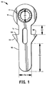
- FIG. 1 shows a front view of a preferred embodiment of a flexible lamp tube support 10 with a lamp tube 11 in cross section.
- the flexible lamp tube support 10 includes a lamp coupler 12 to support the lamp 11, a through connector 14, and a compressible latch portion 16, and a pull tab 18.
- the lamp support 10 is formed as a unitary body from a flexible, compressible and relatively heat insulating material such as a silicon rubber.
- the lamp support 10 was cut from a flat sheet of silicon rubber.
- the described structure may be formed as individually molded pieces with some of the sections being formed symmetrically in three dimensions. Further, while it is particularly convenient to form the structure as a single piece of silicon rubber, it should be understood that the functions of the various sections may be achieved with separate segments with separate materials, the various segments being joined to function as a unit.
- the lamp tube being supported is understood to be tubular, with a straight circular cylindrical form being the simplest. Curved tubes, are specifically anticipated and the present design is particularly directed for use with curved or other irregular shaped tubes. Starting from the lamp coupling end the lamp support 10 then has the following subsections.
- the first section is a lamp coupler 12 to hold and support a lamp 11.
- the preferred lamp coupler 12 is ring formed with a passage having an inside opening sized and shaped to admit the insertion of the lamp 11, for example as a round form with a diameter 20. The lamp 11 is then constrain by the surrounding ring.
- the use of silicon rubber for the lamp coupler 12 is preferred as it is both cushioning and provides relatively little heat conduction from the lamp.
- Fig. 2 shows a front view of an alternative embodiment of a lamp support with a clip on coupler 22.
- a semicircular clip 22, or similar three point coupler that snaps on transverse to the lamp axis is likely functional.
- a stiffer material is needed to support the clip function.
- the convenience of the clip on feature must be weighed against the possibility of equally simple failure of unclipping.
- the Applicants prefer a complete ring, that can be relatively more cushioning, and at the same time less prone to a possible dismounting failure.
- the lamp coupler 12 may also include a rib, circumferential edge, or other circumferential features for latching, grasping, coupling, holding, sealing, stopping or limiting passage of the lamp coupler 12 too far into the hole 30.
- the lamp coupler 12 is immediately adjacent the through connector 14, and thereby acts to block further passage of the lamp coupler 12.
- FIG. 3 shows a perspective view of an alternative embodiment of a flexible lamp tube support.
- positioned intermediate the lamp coupler 12 and the through connection 14 is a stop rib 24.
- the stop rib 24 may be positioned away from where the lamp is located by a displacement distance 26.
- the displacement distance 26 can be adjusted to provide a proper stand off distance between the final lamp position and the lamp housing 34.
- an interior stop rib 24 and exterior stop rib 28 on either end of the through connector 14 are positioned to latch the lamp support 10 in place with respect to the lamp housing 34.
- FIG. 4 shows a front view of a preferred embodiment of a flexible lamp tube support 10 positioned in a lamp housing 34 with a through hole 30 shown in cross section.
- the through hole 30 extends from an interior side 32 of the housing 34, the side facing the lamp, to an exterior side 36 of the housing 34, the side facing away from the lamp.
- the interior wall 38 of the through hole 30 defines a passage length 40 extending from the interior side 32 to the exterior side 36, and a passage cross sectional form.
- the preferred through connector 14 has a connector length 42 and a connector cross sectional form sufficient to fit within, and extend through the defined hole 30.
- the through connector 14 may have any convenient cross sectional form whether planar, triangular, square, polygonal or a circular.
- the through connector 14 has a smaller cross sectional form than does the hole 30, and the relatively thinner through connector 14 then extends easily in the defined hole 30.
- the through connector 14 is sized and shaped to compressibly conform with the wall 38. The relatively fatter through connector 14 then seals the defined hole 30.
- the through connector 14 may also have a slightly smaller length 42 than the length 40 of the hole 30, so that the through connector 14 must be stretched (tensioned) to gain the required slightly additional length. The tension in the through connector 14 can then act to seal one or both ends (lamp coupler 12, and latch portion 16) of the lamp support 10 to the exterior surfaces 32, 36 of the adjacent lamp housing 34.
- a compressible latch portion 16 Extending from the through connector 14, on the exterior side 36 of the lamp housing 34 is a compressible latch portion 16.
- the latch portion 16 has at least one flexible portion sufficiently compressible to pass through the hole 30 in a compressed state, and expandable to subsequently re-expand to an extended state. When in the extended state, the latch portion 16 has a greater cross sectional dimension 44 than does the cross section of the hole 30. The latch portion 16 then inhibits withdrawal of the lamp support 10 from the hole 30, and therefore from the lamp housing 34.
- the latch portion 16 is sized and shaped to circumferentially extend around the exterior side 36 of the wall 38 and compressibly conform with the exterior side 36 of the lamp housing 34. The extended latch portion 16 then seals with exterior side 36, and therefore seals the defined hole 30.
- the through connector 14 or the latch portion 16 or both may be formed with a cavity 46 therein to facilitate compression when passing through the hole 30.
- the cavity may also extend between through connector 14 and the latch portions 16 of the lamp support 10.
- FIG. 5 shows a front view of an alternative lamp support 48 with no pull tab. The alternative lamp support 48 is then pressed into the hole 30, so that the latch portion 50 extends through and expands on exterior side 36.
- FIG, 1, 4, extending from the latch portion 16 is a pull tab 18.
- the pull tab 18 has a length 52 and cross sectional dimension 54 sufficient to be threaded from the interior side 32 through and sufficiently beyond the exterior side 36 of the hole 30 to facilitate positioning of the flexible lamp support 10 in a latched position.
- a tip end of the pull tab 18 may be grasped on the exterior side 36 of the hole 30.
- the latch portion 16 may them be pulled through to secure the latching.
- the formed stops 56, 58 along the latch portion 16 to limit the lamp support 10 from being pull back through the hole 30.
- the lamp is then well centered in directions transverse to the axis of the lamp support 10. This assures good optical positioning in a reflector (e.g.
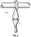
- FIG. 6 shows a front view of an alternative embodiment of a flexible lamp tube support 60 with a conical stop 62.
- FIG. 7 shows a front view of an alternative embodiment of a flexible lamp tube support 64 with a spherical stop 665.
- the lamp support was cut from a sheet of silicon rubber.
- the sheet was approximately about 1.5 millimeters thick.
- Formed on one end was a ring with an outside diameter of about 8.0 millimeters and inside diameter of about 4.57 millimeters which was sufficient to receive and support a 5.0 millimeters outside diameter neon lamp.
- Extending from the ring was straight section about 3.05 millimeters long and 3.81 millimeters wide that served as the through connector.
- the compressible latch portion was next in series, having the form of wedge shaped arms extending 7.62 across both arms.
- the wedge extended about 3.05 millimeters axially to a pull tab portion with a length of about 9.0 millimeters and a width of 3.81 millimeters. Formed between the ring and the pull tab, in the middle of the through connector and the latch portion was an interior cavity about 5.08 millimeters long and 1.52 millimeters wide that enhanced the passage of the through connector and latch portion through the housing passage.
- the disclosed operating conditions, dimensions, configurations and embodiments are as examples only, and other suitable configurations and relations may be used to implement the invention.
Landscapes
- Engineering & Computer Science (AREA)
- General Engineering & Computer Science (AREA)
- Fastening Of Light Sources Or Lamp Holders (AREA)
Applications Claiming Priority (2)
| Application Number | Priority Date | Filing Date | Title |
|---|---|---|---|
| US160810 | 1998-09-25 | ||
| US09/160,810 US5908237A (en) | 1998-09-25 | 1998-09-25 | Flexible lamp tube support |
Publications (2)
| Publication Number | Publication Date |
|---|---|
| EP0989634A2 true EP0989634A2 (de) | 2000-03-29 |
| EP0989634A3 EP0989634A3 (de) | 2000-05-24 |
Family
ID=22578547
Family Applications (1)
| Application Number | Title | Priority Date | Filing Date |
|---|---|---|---|
| EP99118673A Withdrawn EP0989634A3 (de) | 1998-09-25 | 1999-09-22 | Flexible Abstützung für eine rohrförmige Lampe |
Country Status (3)
| Country | Link |
|---|---|
| US (1) | US5908237A (de) |
| EP (1) | EP0989634A3 (de) |
| CA (1) | CA2277338A1 (de) |
Families Citing this family (4)
| Publication number | Priority date | Publication date | Assignee | Title |
|---|---|---|---|---|
| JP4155969B2 (ja) | 2004-01-14 | 2008-09-24 | シャープ株式会社 | 表示装置用照明装置 |
| TWM314867U (en) * | 2006-11-27 | 2007-07-01 | Innolux Display Corp | Backlight module |
| US20100124066A1 (en) * | 2008-11-17 | 2010-05-20 | Yu-Chu Lin | Cold cathode fluorescent lamp lighting device |
| KR101750116B1 (ko) * | 2010-11-30 | 2017-06-22 | 엘지이노텍 주식회사 | 후크 터미널 |
Family Cites Families (5)
| Publication number | Priority date | Publication date | Assignee | Title |
|---|---|---|---|---|
| US4244012A (en) * | 1978-06-29 | 1981-01-06 | Computervision Corporation | Lamp holder for projection aligner |
| DK147803C (da) * | 1981-08-07 | 1985-05-20 | Scandinavisk Reflektor Compagn | Reflektorsystem til fastgoerelse paa en lyskilde |
| JPS6290883A (ja) * | 1985-06-13 | 1987-04-25 | ヒロセ電機株式会社 | 電気接触ピンの製造方法 |
| US4812955A (en) * | 1988-04-12 | 1989-03-14 | Truck-Lite Co., Inc. | Modular shock resistant/sealed multi-function lamp |
| US5541823A (en) * | 1995-02-16 | 1996-07-30 | Fallon Luminous Products Corp. | Housing assembly for illuminated glass tubing |
-
1998
- 1998-09-25 US US09/160,810 patent/US5908237A/en not_active Expired - Fee Related
-
1999
- 1999-07-09 CA CA002277338A patent/CA2277338A1/en not_active Abandoned
- 1999-09-22 EP EP99118673A patent/EP0989634A3/de not_active Withdrawn
Also Published As
| Publication number | Publication date |
|---|---|
| US5908237A (en) | 1999-06-01 |
| CA2277338A1 (en) | 2000-03-25 |
| EP0989634A3 (de) | 2000-05-24 |
Similar Documents
| Publication | Publication Date | Title |
|---|---|---|
| KR940009345B1 (ko) | 세경배관 접속용 커넥터 | |
| JP2530220Y2 (ja) | 細径配管接続用コネクター | |
| KR960006181B1 (ko) | 가는 관 접속용 커넥터 | |
| USD459205S1 (en) | Concrete dowel tube with clip | |
| US5908237A (en) | Flexible lamp tube support | |
| EP1033742A3 (de) | Bogenröhre, Montageelement und elektrische Lampenanordnung | |
| US6018218A (en) | Fluorescent lamp with internal glass tube | |
| JP3245647B2 (ja) | パイプ継手 | |
| GB2151735A (en) | Hose coupling | |
| JP2007527976A (ja) | 自動車のダクト用瞬時連結装置 | |
| JPH0638113U (ja) | 管状ランプのランプホルダ | |
| JPH0861348A (ja) | 締結具及び締結具用キャップ | |
| AU2003227629A1 (en) | Louver provided with double sided lateral reflectors | |
| EP1033739B1 (de) | Lampe mit einem aufsetzbaren Kolbenhalter und Klemmring | |
| US6555965B1 (en) | Integral housing for low profile fluorescent lamp | |
| JP4189245B2 (ja) | 配線引き込み部の防水構造 | |
| JP2001023575A (ja) | 低温用照明器具 | |
| JPH04224394A (ja) | 配管用コネクタ | |
| BR0305747A (pt) | Conexão de monobloco para tubulações | |
| JP4345887B2 (ja) | ガラス管ヒータ用キャップとガラス管ヒータと冷蔵庫 | |
| JP5034113B2 (ja) | 照明装置 | |
| KR0130646Y1 (ko) | 자동차 에어컨용 파이프의 체결 장치 | |
| JP3077533B2 (ja) | 空気調和機用室外機のサーミスタ取付構造 | |
| KR200332584Y1 (ko) | 크린룸의 램프 홀딩장치 | |
| KR0135545Y1 (ko) | 부품 조립용 체결부재의 구조 |
Legal Events
| Date | Code | Title | Description |
|---|---|---|---|
| PUAI | Public reference made under article 153(3) epc to a published international application that has entered the european phase |
Free format text: ORIGINAL CODE: 0009012 |
|
| 17P | Request for examination filed |
Effective date: 19991020 |
|
| AK | Designated contracting states |
Kind code of ref document: A2 Designated state(s): BE DE FR GB IT NL |
|
| AX | Request for extension of the european patent |
Free format text: AL;LT;LV;MK;RO;SI |
|
| PUAL | Search report despatched |
Free format text: ORIGINAL CODE: 0009013 |
|
| RIN1 | Information on inventor provided before grant (corrected) |
Inventor name: AUDETTE, DOREEN R. Inventor name: SCHMIDT, ROBERT J Inventor name: DEVIR, DANIEL D. |
|
| AK | Designated contracting states |
Kind code of ref document: A3 Designated state(s): AT BE CH CY DE DK ES FI FR GB GR IE IT LI LU MC NL PT SE |
|
| AX | Request for extension of the european patent |
Free format text: AL;LT;LV;MK;RO;SI |
|
| RIC1 | Information provided on ipc code assigned before grant |
Free format text: 7H 01R 33/08 A, 7F 21V 15/04 B, 7H 01R 35/02 B |
|
| AKX | Designation fees paid |
Free format text: BE DE FR GB IT NL |
|
| 17Q | First examination report despatched |
Effective date: 20030801 |
|
| STAA | Information on the status of an ep patent application or granted ep patent |
Free format text: STATUS: THE APPLICATION HAS BEEN WITHDRAWN |
|
| 18W | Application withdrawn |
Effective date: 20031208 |