EP0989671A2 - Capteur à effleurement pour l'identification d'une partie du corps - Google Patents
Capteur à effleurement pour l'identification d'une partie du corps Download PDFInfo
- Publication number
- EP0989671A2 EP0989671A2 EP99118998A EP99118998A EP0989671A2 EP 0989671 A2 EP0989671 A2 EP 0989671A2 EP 99118998 A EP99118998 A EP 99118998A EP 99118998 A EP99118998 A EP 99118998A EP 0989671 A2 EP0989671 A2 EP 0989671A2
- Authority
- EP
- European Patent Office
- Prior art keywords
- electrodes
- touch sensor
- pair
- sensor according
- body part
- Prior art date
- Legal status (The legal status is an assumption and is not a legal conclusion. Google has not performed a legal analysis and makes no representation as to the accuracy of the status listed.)
- Withdrawn
Links
Images












Classifications
-
- H—ELECTRICITY
- H03—ELECTRONIC CIRCUITRY
- H03K—PULSE TECHNIQUE
- H03K17/00—Electronic switching or gating, i.e. not by contact-making and –breaking
- H03K17/94—Electronic switching or gating, i.e. not by contact-making and –breaking characterised by the way in which the control signals are generated
- H03K17/96—Touch switches
- H03K17/962—Capacitive touch switches
-
- H—ELECTRICITY
- H03—ELECTRONIC CIRCUITRY
- H03K—PULSE TECHNIQUE
- H03K17/00—Electronic switching or gating, i.e. not by contact-making and –breaking
- H03K17/94—Electronic switching or gating, i.e. not by contact-making and –breaking characterised by the way in which the control signals are generated
Definitions
- This invention relates to a touch sensor to detect the touch of a body part and in particular, to a touch sensor to detect the touch of a human finger for use in various electronic applications and security devices.
- Conventional touch sensors do not have a capacity to determine whether the object touching the sensor is actually a finger. While some of the conventional inductance, electrical conductivity and high-frequency radiation sensors are not supposed to react unless they are touched by a finger, it is relatively easy to operate the sensors by intentionally touching them with an object having characteristics similar to a finger. That is, the conventional sensors are unable to properly discriminate. Detecting coils, for example, detect the presence of a human body before they are actually being touched, so they have a problem of accuracy in that they cannot determine whether the sensor was in fact touched by the human body.
- the invention provides a touch sensor which is able to detect the touch of a finger with reasonable accuracy.
- a touch sensor includes an oscillator unit which outputs a high-frequency signal; an electrode unit which receives the high-frequency signal from the oscillator unit and which includes electrodes that are touched by the finger to be detected; a detector unit which outputs a signal which varies with the impedance of the electrode unit; a discriminator unit which determines whether the item detected is alive; and a reference unit in which a reference signal is stored prior to use to determine whether the item detected is a human body part.
- the oscillator unit supplies a high-frequency signal to the electrode unit. If the item detected is a biological entity of a human body such as a finger, then the impedance of the electrode unit will change. The impedance is initially composed to the impedance on the input side of the electrode when the finger is touching the electrodes. The reflected wave will be smaller due to the change in impedance when the finger is touching the electrodes. By detecting this reflected wave and comparing it with a reference signal in the discriminator unit, it can be determined that the reflection level is lower and that the electrodes are being touched by a person.
- a method of sensing a touch of a body part includes...
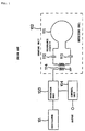
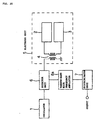
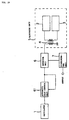
- FIG. 2 is an exemplary block diagram of a touch sensor according to the first preferred embodiment of this invention.
- the touch sensor of this embodiment is designed to detect whether it has been touched by a finger.
- the touch sensor comprises an oscillator unit 1 which generates and emits a high-frequency signal, an electrode unit 5 which includes a pair of electrodes 2 and 3 and a transformer 4 which is used for an impedance comparison, a detector unit 6 which detects the level of the high-frequency signal supplied by oscillator unit 1 to electrode unit 5 and reflected by it, and a discriminator unit 7 which determines from the amplitude of the detected signal whether the touch sensor is touched by a finger.
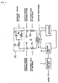
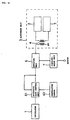
- Figure 3 is an exemplary diagram of an equivalent circuit which illustrates the principle of detection used in the touch sensor in Figure 2.
- the secondary side of transformer 4 is in an open state.
- the resistance values R 2 and R 3 of electrodes 2 and 3 When the area between electrodes 2 and 3 is touched, the resistance values R 2 and R 3 of electrodes 2 and 3, the capacitance values C 2 and C 3 between electrodes 2 and 3 and the finger, and the equivalent circuit FE of the finger, which includes a capacitor C 4 and resistors R 4 and R 5 , are serially connected to the secondary coil of transformer 4.
- the capacitance between the finger and electrodes 2 and 3 increases and the high-frequency impedance value of the finger is compared to the reference value.
- the discriminator determines that the touch is that of a finger.
- the impedance measured on the secondary side of transformer 4, when a finger touches the electrodes can be used as a criterion for comparison.
- the level of the high-frequency signal from oscillator unit 1, after it is reflected by electrode unit 5 determines whether the sensor has been touched by a finger.
- the resistance value R 4 + R 5 of the finger is approximately 40 ⁇
- the resistance value R 2 + R 3 is approximately 30 ⁇
- the capacitance when the finger is touching the electrodes is approximately 3000 PF
- the reactive component 1/2 ⁇ fc of capacitance C is 1.3 ⁇ (40.68 MHz)
- the total impedance is 102.6 ⁇ .
- the transformer 4 If the transformer 4 is set at approximately 50:100, then its impedance will be approximately 50 ⁇ when a finger is touching the sensor, and the values will be compared. If the compared values are set so that a match is defined as a finger touching the sensor, the comparison will not match when the sensor is touched by an object other than a finger, since it will have a different impedance value. If the item detected does not come in contact with the electrodes, then the capacitance will drop, and the reactive component of C will increase, and as a result, the values will not match. When the capacitance drops at this time, the imaginary component of the impedance will increase. Thus, even if the resistance components match, the imaginary quantities would not, and the touch sensor would not recognize the object as a finger.
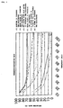
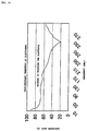
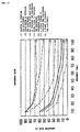
- Figure 4 is a graph of the relationship between the frequency and the reflected wave amplitude. The values are set so that a comparison of the impedance values match when a finger is touching the electrodes. Since the level of the reflected wave is set quite low when the thumb or little finger touches the detector, the threshold value of discriminator unit 7 should be set somewhat higher than the detected level for the little finger. This will ensure that discriminator unit 7 can detect the touch of a finger.
- This embodiment of the touch sensor has two conditions: (1) the item makes contact with the electrodes just as a finger does, and (2) it has the same impedance component as a finger. This requirement keeps false positives to a minimum.
- the sensor is virtually immune to electromagnetic fields.
- the sensor employs ISM frequency, so it is not subject to laws governing radio or is it affected by radio interference. It can run on 1 mW of electricity, so it has no adverse effects on human beings. Other benefits may also be realized.
- the electrodes 2 and 3 which enable the touch sensor to detect a finger in the embodiment discussed above, are symmetrically opposed to the left and right with a gap of 1 mm in between. They may be of various shapes, such as rectangular, as shown in Figure 5 (a), semicylindrical, as shown in Figure 5 (b), triangular, as shown in Figure 6 (a), or sword-shaped, as shown in Figure 6 (b).
- transformer 4 is used to match the impedance between electrodes 2 and 3 and the supply side of oscillator unit 1.
- a ⁇ -type impedance converter circuit comprising capacitors C 11 and C 12 and coil L may be used.
- a T-type or L-type impedance converter circuit may also be used for impedance matching.
- electrode unit 5 As well as the circuitry for oscillator unit 1, detector unit 6 and discriminator unit 7 are all housed in a single case.
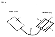
- electrode unit 5 and a circuit unit 11 are separate entities which are connected by a cable 12, forming a detached-type touch sensor.
- circuit unit 11 would contain oscillator unit 1, detector unit 6 and discriminator unit 7. This arrangement can prove helpful when the space for the touch sensor is limited.
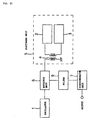
- the circuit layout for this embodiment of the touch sensor is shown in Figure 10. A coaxial cable is used for cable 12, and transformer 4 is housed in electrode unit 5.
- FIG 11 is an exemplary block diagram of another circuit layout for a detached-type touch sensor.
- a balanced line is used as cable 12, and the design differs from that shown in Figure 10 in that transformer 4 is placed in circuit unit 11.
- FIG 12 exemplary the electrodes in the above-described embodiment of a touch sensor, without transformer 4.
- (a) is a plan view and (b) is a cross sectional view.
- electrodes 2 and 3 which are made of ITO film, are formed on a glass substrate 13. They are then covered by a protective layer of SiO 2 film 14.
- a thicker layer of SiO 2 film 14 would seem desirable, however, a thinner layer is called for, as a thicker film would cause the capacitance C component to be unattainable.
- the thickness that is chosen for the SiO 2 film 14 is 1500 ⁇ .
- the electrodes 2 and 3 shown in Figures 5, 6 and 12 have a large, flat area.
- the electrodes 2 and 3 take the form of long rods. These sort of electrodes could be placed along the top of a car window glass 15, where they could serve as sensors to prevent a passenger's fingers from being caught when the power window of an automobile closes. In this case, the electrodes would extend all along the top edge of window glass 15.
- the capacitance between electrodes 2 and 3 in the above-described embodiment of a touch sensor depends upon the thickness of the SiO 2 film 14, shown in Figure 12. However, the capacitance will rise only to the level of 500 PF when a (solid) non-biological substance comes in contact with electrodes 2 and 3. When a human being comes in contact with the electrodes, on the other hand, the capacitance will rise to 3000 PF. Thus, the threshold was chosen as 500 PF, and the system was designed so that the capacitance becomes more than 500 PF when a living being comes in contact with the electrodes.
- this embodiment of a touch sensor can be used both as a touch sensor, when combined with a light, and in a fingerprint recognition system, the electrodes must allow light to pass through.
- the transmissivity of electrodes 2 and 3 is therefore specified to be greater than 50%.
- an ITO membrane can be used for electrodes 2 and 3.
- electrodes 2 and 3 If it is not necessary for light to pass through electrodes 2 and 3, they should be made of a material which is a good conductor of high-frequency radiation. This is important if the electrodes are long. Materials which are good high-frequency conductors include, for example, silver, gold, copper and aluminum. If electrodes 2 and 3 need not be translucent and they are to be relatively short, then detection can be accomplished by the use of semiconductors.
- this embodiment of a touch sensor can use any frequency over a wide band without resonance, substances vary in their frequency characteristics as shown in Figure 4. If a frequency switching device to switch frequencies is added to the touch sensor so that a variety of frequencies can be used, then the selectivity of the sensor will be improved.
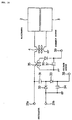
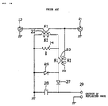
- FIG. 15 is an exemplary diagram of the actual circuits in detector unit 6 of the above mentioned embodiment of a touch sensor.
- the primary winding (winding N 1 ) of M coupling coil 22 is connected between terminal 21, to which oscillator unit 1 is connected, and terminal 23, to which electrode unit 5 is connected.
- One terminal (C) of resistor 24 is connected to ground.
- One end of the primary winding (winding N 1 ) of M coupling coil 25 is connected to the other terminal (A) of resistor 24.
- the other terminal (BL) of the primary winding of M coupling coil 25 is connected to the cathode of diode 26 and the anode of diode 27.
- the cathode of diode 27 is connected to one terminal of capacitor 28 and output terminal 29.
- the anode of diode 26 and the other terminal of capacitor 28 are connected to ground.
- Diodes 26 and 27 and capacitor 28 constitute a rectifier circuit (i.e., a circuit to detect the wave).
- the secondary winding of M coupling coil 25 is connected between terminal 21 and the ground.
- the impedance as seen from the primary side of M coupling coil 22 is R(N 1 /N) 2 . If the resistance at terminal 23 is 50 ⁇ , then the resistance at terminal 21 is 50 + R(N 1 /N) .
- the power which can be obtained on the secondary side of M coupling coil 22 is PR(N 1 /N) 2 /50 + R(N 1 /N) 2 .
- the voltage under AC is ⁇ PR 2 (N 1 /N) 2 /50 + R(N 1 /N) 2 .
- the voltage between A and B is N 1 /N 2 ⁇ 50P + PR(N 1 /N) 2 .
- the reflected wave signal which is led through the secondary side of M coupling coil 22 is rectified by the circuit comprising diodes 26 and 27 and capacitor 28 and output via output terminal 29.
- Detector unit 6 may also detect the voltage and current of the power supplied to electrode unit 5.
- An example of this circuit is shown in Figure 16.
- an oscillator unit is connected to terminals 21a and 21b.
- One end of capacitor 31 is connected to terminal 21 and the other to the cathode of diode 32 and the anode of diode 33.
- the anode of diode 32 is connected to ground.
- the cathode of diode 33 is connected to one end of capacitor 34 and to output terminal 38.
- the other end of capacitor 34 is connected to ground.
- the voltage output is obtained from output terminal 38.
- One end of the primary winding of M coupling coil 35 is connected to terminal 21a.
- the other end of the primary winding is connected to transformer 4 of electrode unit 3.
- the anode of diode 36 is connected to one end of the secondary winding of M coupling coil 35, the other end is connected to ground.
- the cathode of diode 36 is connected to one end of capacitor 37 and to output terminal 39, while the other end of capacitor 37 is connected to ground.
- the current output is obtained at output terminal 39. Alternatively, the output of either voltage or current may be obtained singly.
- detector unit 6 detects the wave, immediately converts it to DC and amplifies it with an operational amplifier or the like.
- a low-priced operational amplifier with a single power supply may be used, setting the amplification factor higher.
- the offset voltage of the operational amplifier would be amplified and the offset voltage of the output voltage would be higher. This would adversely affect the resolution of the control unit (i.e., the discriminator unit 6).
- a high-frequency amplifier 8 is provided directly behind detector 6, as shown in Figure 17. Because the voltage is high after the wave is detected and converted to DC, an operational amplifier with a lower amplification factor can be used. It is also possible to dispense of the amplifier altogether. In this way the resolution of the sensor can be enhanced.
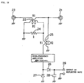
- Figure 19 is the actual circuit used in Figure 17.
- Amplifier 8 is placed at a location before the circuit where diodes 26 and 27 detect the wave, and there it amplifies the signal.
- Amplifier 8 may be an IC, or a circuit may be assembled for it using a transistor or FET.
- a filter 9 at the frequency of use is placed between detector unit 6 and discriminator unit 7.
- the filter even if other frequency components should intrude from electrode unit 5, they will be eliminated by the filter. This will prevent the sensor from malfunctioning. Also, since a signal at the frequency of use is selectively received, the sensitivity of the sensor is improved.
- Figure 22 shows several examples of a circuit for filter 9.
- Figure 22 (a) is a low-pass filter (LPF) circuit;
- Figure 22 (b) is a high-pass filter (HPF) circuit;
- Figure 22 (c) is a band-pass filter (BPF) circuit.
- LPF low-pass filter
- HPF high-pass filter
- BPF band-pass filter
- FIG 23 shows an example of a circuit for discriminator unit 7.
- Comparator 41 compares the detected voltage with a reference voltage, but the signal from the detector unit 7 is amplified by operational amplifier 42 before it is fed to comparator 41.
- Operational amplifier 42 uses a diode 43 which is the same as that used to detect the wave in the detector unit 7. This arrangement is made because the detecting diode may exhibit variations in output voltage depending on the ambient temperature. To compensate for this, it is desirable that the rectification in the late-stage amplifier be achieved by an identical diode.
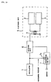
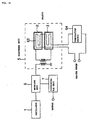
- Figure 24 is an exemplary block diagram of another embodiment of a touch sensor.
- the output of oscillator unit 1 is input to discriminator unit 7.
- Circuit 7a in discriminator unit 7 detects the waveform of the output of oscillator unit 1 and uses it as a reference voltage for the discriminator unit 7. Even if the output of oscillator unit 1 changes so that the output of detector unit 6 varies, the reference voltage will vary correspondingly. Since the reference voltage responds to variations in the oscillator, the sensor will still be able to function normally unless the oscillator stops working or breaks completely.
- Figure 25 is an exemplary block diagram of another embodiment of a touch sensor.
- the output voltage of the diode in detector unit 6 which detects the wave varies with the ambient temperature.
- discriminator unit 7 uses the output of oscillator unit 1 as its reference voltage. Since this detector circuit uses the same diode as that used to detect the waveform in detector unit 6, it can perform in a stable fashion regardless of temperature variations.
- Figure 26 is an exemplary block diagram of another embodiment of a touch sensor.
- This embodiment has a temperature sensor 10 in discriminator unit 7.
- the reference voltage used in discriminator unit 7 is varied to correct for the temperature characteristics of the detecting diode in detector unit 6. This makes the performance of detector unit 6 more stable.
- the reflected wave varies according to the frequency as shown in Figure 27.
- the voltage should be measured when the output value becomes lower than the value shown in Figure 27.
- FIG 28 is an exemplary block diagram of yet another embodiment of a touch sensor.
- This embodiment has an attenuator 60 between oscillator unit 1 and detector unit 6.
- the output of oscillator unit 1 normally remains stable in the face of changes in load impedance due to the presence of a body part.
- attenuator 60 mitigates the load-dependent variation of the output of oscillator unit 1 to ensure that the performance of the detector remains stable. Even with a substantial loss component, the attenuator 60 ensures that the oscillator unit 1 will perform in a stable fashion. However, since an excessive portion of the power going through will be lost if the loss fraction becomes too great, it is best to keep it at around 50%.
- Figure 29 is an exemplary block diagram of still another embodiment of a touch sensor.
- This embodiment has an automatic gain control unit 61 between oscillator unit 1 and detector unit 6.
- Automatic gain control circuit 61 stabilizes the output of oscillator unit 1 and sends it to electrode unit 5. This improves the accuracy of detection.
- Figure 30 has a temperature sensor 62 in addition to the circuit shown in Figure 29. To compensate for the temperature characteristics of the diode in detector unit 6, a temperature sensor 62 and an automatic gain control circuit 61 are provided. If the temperature drops, the output voltage of oscillator 1 is boosted. In this way the temperature of the diode can be compensated for.
- FIG 31 is an exemplary block diagram of still another embodiment of a touch sensor.
- This embodiment has a heater 63 in electrode unit 5. Electrodes 2 and 3 are formed on top of heater 63. The temperature of electrodes 2 and 3 is kept constant by temperature switch 64. Electrode unit 5 is the location where a person is to touch the sensor. At temperatures below zero, however, it is unsafe to do so. Heater 63 and temperature sensor 64 in electrode unit 5 allow the unit to be heated at low temperatures.
- the impedance of a circuit changes when a human being touches an electrode, and a signal is detected which corresponds to this change in impedance. From this signal, a discriminator unit makes a determination whether someone has touched the electrode.
- the touch sensor will not respond if the object which touches the electrode is not an actual finger, so it can discriminate accurately when it is touched by something else.
- the sensor has stable temperature characteristics. The sensor needs no adjustment and provides a high degree of security. That is, it is extremely difficult to fabricate a human body part, in particular, a finger.
- the sensor is virtually immune to electromagnetic fields. Since the sensor requires little power, the adverse effects on human beings is extremely small.
Landscapes
- Electronic Switches (AREA)
- Geophysics And Detection Of Objects (AREA)
- Measurement And Recording Of Electrical Phenomena And Electrical Characteristics Of The Living Body (AREA)
Applications Claiming Priority (2)
| Application Number | Priority Date | Filing Date | Title |
|---|---|---|---|
| JP27272898 | 1998-09-28 | ||
| JP27272898A JP3484355B2 (ja) | 1998-09-28 | 1998-09-28 | 生体検知装置 |
Publications (2)
| Publication Number | Publication Date |
|---|---|
| EP0989671A2 true EP0989671A2 (fr) | 2000-03-29 |
| EP0989671A3 EP0989671A3 (fr) | 2005-04-20 |
Family
ID=17517962
Family Applications (1)
| Application Number | Title | Priority Date | Filing Date |
|---|---|---|---|
| EP99118998A Withdrawn EP0989671A3 (fr) | 1998-09-28 | 1999-09-27 | Capteur à effleurement pour l'identification d'une partie du corps |
Country Status (3)
| Country | Link |
|---|---|
| US (1) | US6545614B1 (fr) |
| EP (1) | EP0989671A3 (fr) |
| JP (1) | JP3484355B2 (fr) |
Cited By (10)
| Publication number | Priority date | Publication date | Assignee | Title |
|---|---|---|---|---|
| GB2345140B (en) * | 1998-12-10 | 2003-07-23 | Omron Tateisi Electronics Co | Fingerprint identification device equipped with a touch sensor for detecting a human finger |
| EP1302908A3 (fr) * | 2001-10-09 | 2004-06-09 | BMF Corporation | Techniques de vérification pour les systèmes d'identification biométrique |
| EP1629817A1 (fr) * | 2004-08-30 | 2006-03-01 | Omron Healthcare Co., Ltd. | Appareil de massage |
| EP1629818A1 (fr) * | 2004-08-30 | 2006-03-01 | Omron Healthcare Co., Ltd. | Appareil de massage |
| EP1629816A1 (fr) * | 2004-08-30 | 2006-03-01 | Omron Healthcare Co., Ltd. | Appareil de massage |
| WO2007015991A1 (fr) * | 2005-07-27 | 2007-02-08 | Tyco Electronics Corporation | Circuit de detection de touche a effleurement et systeme associe |
| WO2008017136A3 (fr) * | 2006-08-09 | 2008-04-24 | Flavio Zampieri | Touches à effleurement |
| NL1034544C2 (nl) * | 2007-10-18 | 2009-04-21 | Erik De Rooy | Massageapparaat. |
| KR101046455B1 (ko) * | 2010-10-29 | 2011-07-04 | 유미혜 | 앰프 회로 및 그 전압 보상 방법 |
| JP2014007629A (ja) * | 2012-06-26 | 2014-01-16 | Kyushu Institute Of Technology | 近接センサ |
Families Citing this family (35)
| Publication number | Priority date | Publication date | Assignee | Title |
|---|---|---|---|---|
| KR100366503B1 (ko) * | 2000-06-13 | 2003-01-09 | 주식회사 엘지이아이 | 글래스 터치 감지회로 |
| DE10138885A1 (de) * | 2001-08-08 | 2003-02-20 | Bsh Bosch Siemens Hausgeraete | Haushaltsgerät |
| JP4383730B2 (ja) * | 2002-10-22 | 2009-12-16 | アルプス電気株式会社 | タッチセンサを有する電子機器 |
| JP2004311196A (ja) * | 2003-04-07 | 2004-11-04 | Alps Electric Co Ltd | 入力装置 |
| WO2005016146A1 (fr) | 2003-08-15 | 2005-02-24 | Nippon Telegraph And Telephone Corporation | Systeme de reconnaissance d'organisme |
| US7675285B2 (en) * | 2004-09-09 | 2010-03-09 | Rockwell Automation Technologies, Inc. | Sensor and method including noise compensation |
| CN1838051A (zh) * | 2005-03-25 | 2006-09-27 | 鸿富锦精密工业(深圳)有限公司 | 触摸式感应装置 |
| CN100419655C (zh) * | 2005-04-08 | 2008-09-17 | 鸿富锦精密工业(深圳)有限公司 | 触摸式感应装置 |
| US7505613B2 (en) * | 2005-07-12 | 2009-03-17 | Atrua Technologies, Inc. | System for and method of securing fingerprint biometric systems against fake-finger spoofing |
| CN100370402C (zh) * | 2005-08-05 | 2008-02-20 | 鸿富锦精密工业(深圳)有限公司 | 触摸式感应装置 |
| CN100489888C (zh) | 2005-08-12 | 2009-05-20 | 鸿富锦精密工业(深圳)有限公司 | 触摸式感应装置 |
| US20070068786A1 (en) * | 2005-09-21 | 2007-03-29 | Lear Corporation | Touch pad having integrated lighting feature and touch sensor and method of operating the same |
| TWI304471B (en) * | 2005-10-14 | 2008-12-21 | Hon Hai Prec Ind Co Ltd | The touch sensing apparatus |
| TWI291124B (en) * | 2005-10-14 | 2007-12-11 | Hon Hai Prec Ind Co Ltd | The touch sensing apparatus |
| CN1952863B (zh) * | 2005-10-18 | 2010-05-05 | 鸿富锦精密工业(深圳)有限公司 | 触摸式感应装置 |
| CN100426211C (zh) * | 2005-10-19 | 2008-10-15 | 鸿富锦精密工业(深圳)有限公司 | 触摸式感应装置 |
| CN100517201C (zh) * | 2005-11-10 | 2009-07-22 | 鸿富锦精密工业(深圳)有限公司 | 触摸式感应装置 |
| TWI298134B (en) * | 2005-11-11 | 2008-06-21 | Hon Hai Prec Ind Co Ltd | The touch sensing apparatus |
| CN100573427C (zh) * | 2005-11-12 | 2009-12-23 | 鸿富锦精密工业(深圳)有限公司 | 触摸式感应装置 |
| CN101004652B (zh) * | 2006-01-21 | 2010-07-28 | 鸿富锦精密工业(深圳)有限公司 | 触摸式感应装置 |
| CN100555194C (zh) * | 2006-02-17 | 2009-10-28 | 鸿富锦精密工业(深圳)有限公司 | 触摸式感应装置及其实现方法 |
| US20080061927A1 (en) * | 2006-08-22 | 2008-03-13 | Russell Hurbert Manton | Biometric lockset |
| JP4931526B2 (ja) * | 2006-09-19 | 2012-05-16 | 日本電信電話株式会社 | インピーダンス検出装置、インピーダンス検出方法、生体認識装置、および指紋認証装置 |
| JP4732990B2 (ja) * | 2006-09-19 | 2011-07-27 | 日本電信電話株式会社 | インピーダンス検出装置、インピーダンス検出方法、生体認識装置、および指紋認証装置 |
| JP4943807B2 (ja) * | 2006-10-18 | 2012-05-30 | 日本電信電話株式会社 | インピーダンス検出装置、インピーダンス検出方法、生体認識装置、および指紋認証装置 |
| GB0705564D0 (en) * | 2007-03-23 | 2007-05-02 | Univ Birmingham | Feedback device |
| KR101590043B1 (ko) * | 2009-05-18 | 2016-02-01 | 삼성전자주식회사 | 인체 통신을 이용한 기능 수행 방법 및 그를 수행하는 단말기 |
| US8068011B1 (en) | 2010-08-27 | 2011-11-29 | Q Street, LLC | System and method for interactive user-directed interfacing between handheld devices and RFID media |
| JP2014515147A (ja) | 2011-06-21 | 2014-06-26 | エンパイア テクノロジー ディベロップメント エルエルシー | 拡張現実のためのジェスチャベースユーザインターフェース |
| AT512878B1 (de) * | 2012-04-23 | 2015-10-15 | Thomas Schlegl | Vorrichtung zur Lokalisierung und Unterscheidung von Objekten an Sensorgebieten |
| EP2961037B1 (fr) | 2013-02-19 | 2017-06-28 | Panasonic Intellectual Property Management Co., Ltd. | Dispositif de détection d'objet étranger, procédé de détection d'objet étranger et système de charge sans contact |
| JP6218170B2 (ja) * | 2013-10-15 | 2017-10-25 | 国立研究開発法人産業技術総合研究所 | 物体の状態検出装置 |
| US9606682B2 (en) * | 2014-04-21 | 2017-03-28 | Avago Technologies General Ip (Singapore) Pte. Ltd. | Wearable device for generating capacitive input |
| KR101557619B1 (ko) | 2015-05-14 | 2015-10-07 | (주)하배런메디엔뷰티 | 고주파 치료장치 |
| US10229304B2 (en) * | 2015-06-05 | 2019-03-12 | Synaptics Incorporated | Finger detection with auto-baseline tracking |
Family Cites Families (19)
| Publication number | Priority date | Publication date | Assignee | Title |
|---|---|---|---|---|
| FR2079504A5 (fr) * | 1970-02-03 | 1971-11-12 | Prototype Ind | |
| US4103252A (en) * | 1976-11-26 | 1978-07-25 | Xerox Corporation | Capacitive touch-activated transducer system including a plurality of oscillators |
| US4237421A (en) * | 1978-10-19 | 1980-12-02 | General Electric Company | Single-electrode capacitance touchpad sensor systems |
| AU5341879A (en) * | 1978-12-08 | 1980-06-12 | Lawrence Security Services Ltd. | Capacitive alarm system for shop shelves |
| DE3111684A1 (de) * | 1981-03-25 | 1982-10-14 | FHN-Verbindungstechnik GmbH, 8501 Eckental | "elektronische steuerschaltung fuer den antriebsmotor eines versenkbaren autofensters" |
| US4394643A (en) * | 1981-04-29 | 1983-07-19 | Whirlpool Corporation | Capacitive touch panel control |
| GB2232251A (en) * | 1989-05-08 | 1990-12-05 | Philips Electronic Associated | Touch sensor array systems |
| JPH0514164A (ja) * | 1991-06-28 | 1993-01-22 | Matsushita Electric Ind Co Ltd | タツチセンサ |
| JPH0769767B2 (ja) * | 1991-10-16 | 1995-07-31 | インターナショナル・ビジネス・マシーンズ・コーポレイション | フィンガ・タッチまたはスタイラスの位置を検出するためのタッチ・オーバーレイ、および検出システム |
| US5235319A (en) * | 1992-05-11 | 1993-08-10 | Joseph C. Hill | Patient monitoring system |
| US5543588A (en) * | 1992-06-08 | 1996-08-06 | Synaptics, Incorporated | Touch pad driven handheld computing device |
| US5463388A (en) * | 1993-01-29 | 1995-10-31 | At&T Ipm Corp. | Computer mouse or keyboard input device utilizing capacitive sensors |
| US6476798B1 (en) * | 1994-08-22 | 2002-11-05 | International Game Technology | Reduced noise touch screen apparatus and method |
| JPH0943007A (ja) | 1994-11-30 | 1997-02-14 | Omron Corp | 検知装置、検知方法、及びセンサ |
| US5650597A (en) * | 1995-01-20 | 1997-07-22 | Dynapro Systems, Inc. | Capacitive touch sensor |
| JPH0946205A (ja) | 1995-05-25 | 1997-02-14 | Omron Corp | 物体検知装置及び人体センサ |
| JP3620558B2 (ja) | 1996-12-16 | 2005-02-16 | ソニー株式会社 | 生体検知装置 |
| US5886687A (en) * | 1997-02-20 | 1999-03-23 | Gibson; William A. | Touch panel system utilizing capacitively-coupled electrodes |
| US6297811B1 (en) * | 1999-06-02 | 2001-10-02 | Elo Touchsystems, Inc. | Projective capacitive touchscreen |
-
1998
- 1998-09-28 JP JP27272898A patent/JP3484355B2/ja not_active Expired - Fee Related
-
1999
- 1999-09-27 EP EP99118998A patent/EP0989671A3/fr not_active Withdrawn
- 1999-09-28 US US09/406,960 patent/US6545614B1/en not_active Expired - Fee Related
Cited By (11)
| Publication number | Priority date | Publication date | Assignee | Title |
|---|---|---|---|---|
| GB2345140B (en) * | 1998-12-10 | 2003-07-23 | Omron Tateisi Electronics Co | Fingerprint identification device equipped with a touch sensor for detecting a human finger |
| US6647133B1 (en) | 1998-12-10 | 2003-11-11 | Omron Corporation | Fingerprint identification device-equip with a touch sensor for detecting a human finger |
| EP1302908A3 (fr) * | 2001-10-09 | 2004-06-09 | BMF Corporation | Techniques de vérification pour les systèmes d'identification biométrique |
| EP1629817A1 (fr) * | 2004-08-30 | 2006-03-01 | Omron Healthcare Co., Ltd. | Appareil de massage |
| EP1629818A1 (fr) * | 2004-08-30 | 2006-03-01 | Omron Healthcare Co., Ltd. | Appareil de massage |
| EP1629816A1 (fr) * | 2004-08-30 | 2006-03-01 | Omron Healthcare Co., Ltd. | Appareil de massage |
| WO2007015991A1 (fr) * | 2005-07-27 | 2007-02-08 | Tyco Electronics Corporation | Circuit de detection de touche a effleurement et systeme associe |
| WO2008017136A3 (fr) * | 2006-08-09 | 2008-04-24 | Flavio Zampieri | Touches à effleurement |
| NL1034544C2 (nl) * | 2007-10-18 | 2009-04-21 | Erik De Rooy | Massageapparaat. |
| KR101046455B1 (ko) * | 2010-10-29 | 2011-07-04 | 유미혜 | 앰프 회로 및 그 전압 보상 방법 |
| JP2014007629A (ja) * | 2012-06-26 | 2014-01-16 | Kyushu Institute Of Technology | 近接センサ |
Also Published As
| Publication number | Publication date |
|---|---|
| JP2000098048A (ja) | 2000-04-07 |
| US6545614B1 (en) | 2003-04-08 |
| JP3484355B2 (ja) | 2004-01-06 |
| EP0989671A3 (fr) | 2005-04-20 |
Similar Documents
| Publication | Publication Date | Title |
|---|---|---|
| US6545614B1 (en) | Touch sensor identifying a body part | |
| US6647133B1 (en) | Fingerprint identification device-equip with a touch sensor for detecting a human finger | |
| US11831178B2 (en) | Wireless power systems with foreign object detection | |
| EP0998659B1 (fr) | Capteur de position et de mouvement a frequence de resonance | |
| KR100189473B1 (ko) | 물체 검지 장치 및 셍체 검지 장치 | |
| US6175641B1 (en) | Detector for recognizing the living character of a finger in a fingerprint recognizing apparatus | |
| US20070177414A1 (en) | Magnetic field probe apparatus and a method for measuring magnetic field | |
| CA2190939A1 (fr) | Detecteur de proximite | |
| US6084551A (en) | Electromagnetic probe for the detection of e-field and h-field radiation | |
| US4829814A (en) | Hot film type air flow meter | |
| KR20190076478A (ko) | 코일을 이용한 인체 감지 장치 및 방법 | |
| US4968947A (en) | Apparatus for the non-destructive measurement of the ohmic resistance of thin layers | |
| CN217847141U (zh) | Rfic模块以及rfid标签 | |
| CN212207517U (zh) | 自互电容检测电路、芯片及设备 | |
| US6147481A (en) | Termination for RF circuit which senses changes in power and which is not temperature sensitive | |
| US20150002172A1 (en) | Conductive Thin Film Detector | |
| US9767339B1 (en) | Fingerprint identification device | |
| US20130032718A1 (en) | Rf immunity improved pyro sensor | |
| US7088089B2 (en) | Power detector with constant voltage decoupling | |
| JP4032565B2 (ja) | パチンコ台及び接触検知器 | |
| KR20050024515A (ko) | 고주파 대전력 신호 측정용 센서 | |
| KR102126302B1 (ko) | 코일을 이용한 인체 감지 장치 및 방법 | |
| KR101994218B1 (ko) | 다중 나선형 코일을 이용한 센서 및 센싱 방법 | |
| JP6745481B2 (ja) | 赤外線検出装置及びその製造方法 | |
| CN113687740A (zh) | 电容式触摸感应板及具有其的电器 |
Legal Events
| Date | Code | Title | Description |
|---|---|---|---|
| PUAI | Public reference made under article 153(3) epc to a published international application that has entered the european phase |
Free format text: ORIGINAL CODE: 0009012 |
|
| 17P | Request for examination filed |
Effective date: 19991021 |
|
| AK | Designated contracting states |
Kind code of ref document: A2 Designated state(s): AT BE CH CY DE DK ES FI FR GB GR IE IT LI LU MC NL PT SE |
|
| AX | Request for extension of the european patent |
Free format text: AL;LT;LV;MK;RO;SI |
|
| RAP1 | Party data changed (applicant data changed or rights of an application transferred) |
Owner name: OMRON HEALTHCARE CO., LTD. |
|
| RAP1 | Party data changed (applicant data changed or rights of an application transferred) |
Owner name: OMRON HEALTHCARE CO., LTD. |
|
| PUAL | Search report despatched |
Free format text: ORIGINAL CODE: 0009013 |
|
| AK | Designated contracting states |
Kind code of ref document: A3 Designated state(s): AT BE CH CY DE DK ES FI FR GB GR IE IT LI LU MC NL PT SE |
|
| AX | Request for extension of the european patent |
Extension state: AL LT LV MK RO SI |
|
| RIN1 | Information on inventor provided before grant (corrected) |
Inventor name: KASAI, EIJI,C/O OMRON HEALTHCARE CO., LTD. |
|
| AKX | Designation fees paid |
Designated state(s): DE FR GB IT |
|
| STAA | Information on the status of an ep patent application or granted ep patent |
Free format text: STATUS: THE APPLICATION IS DEEMED TO BE WITHDRAWN |
|
| 18D | Application deemed to be withdrawn |
Effective date: 20060919 |