EP0989689A2 - Contrôleur de puissance de transmission pour utilisation dans un poste terminal de communication mobile - Google Patents
Contrôleur de puissance de transmission pour utilisation dans un poste terminal de communication mobile Download PDFInfo
- Publication number
- EP0989689A2 EP0989689A2 EP99114086A EP99114086A EP0989689A2 EP 0989689 A2 EP0989689 A2 EP 0989689A2 EP 99114086 A EP99114086 A EP 99114086A EP 99114086 A EP99114086 A EP 99114086A EP 0989689 A2 EP0989689 A2 EP 0989689A2
- Authority
- EP
- European Patent Office
- Prior art keywords
- transmission power
- mobile communication
- communication terminal
- terminal equipment
- signal
- Prior art date
- Legal status (The legal status is an assumption and is not a legal conclusion. Google has not performed a legal analysis and makes no representation as to the accuracy of the status listed.)
- Granted
Links
Images


Classifications
-
- H—ELECTRICITY
- H04—ELECTRIC COMMUNICATION TECHNIQUE
- H04W—WIRELESS COMMUNICATION NETWORKS
- H04W52/00—Power management, e.g. Transmission Power Control [TPC] or power classes
- H04W52/04—Transmission power control [TPC]
- H04W52/52—Transmission power control [TPC] using AGC [Automatic Gain Control] circuits or amplifiers
-
- H—ELECTRICITY
- H04—ELECTRIC COMMUNICATION TECHNIQUE
- H04B—TRANSMISSION
- H04B1/00—Details of transmission systems, not covered by a single one of groups H04B3/00 - H04B13/00; Details of transmission systems not characterised by the medium used for transmission
- H04B1/38—Transceivers, i.e. devices in which transmitter and receiver form a structural unit and in which at least one part is used for functions of transmitting and receiving
- H04B1/40—Circuits
Definitions
- the present invention relates to a transmission power controller for use in a mobile communication terminal equipment.
- Control circuits for controlling the maximum average transmission power to be below a certain value that is stipulated under the Radio Related Law generally include the so-called ALC (Automatic Level Control) circuit in conventional mobile communication terminal equipment of an analog FM (Frequency Modulation) system.
- ALC Automatic Level Control
- Fig.4 exemplifies an arrangement of this circuit.
- VCXO Voltage Controlled Crystal Oscillator 21 generates an IF (Intermediate Frequency) signal that is frequency modulated with a modulation signal.
- Band pass filter 23 restrains a bandwidth for the output signals from VCOX 21 to eliminate undesired waves and allows the IF signal with a desired frequency to pass through.
- IF amplifier 24 amplifies the IF signal output from band pass filter 23.
- Band pass filter 25 restrains a bandwidth for the output signals from IF amplifier 24 to eliminate undesired waves and allows the IF signal with the desired frequency to pass through.
- Mixer 26 mixes the IF signal output from band pass filter 25 with a local signal output from local oscillator 27 to convert the IF signal to a RF (Radio Frequency) signal.
- RF Radio Frequency
- Band pass filter 28 restrains a bandwidth for the output signals from mixer 26 to eliminate undesired waves and allow the RF signal with a desired frequency to pass through.
- the RF signal output from band pass filter 28 is power-amplified at transmission power amplifier 29 and then radiated from antenna 30 as a transmission radio wave.
- Branching filter 31 partly separates the output signal from transmission power amplifier 29.
- Detector 32 detects the output signal from transmission power amplifier 29 separated by branching filter 31.
- Smoothing circuit 33 smoothes the output signal from detector 32.
- a DC voltage hereinafter referred to as a detected voltage
- Threshold setting circuit 34 outputs on the basis of a threshold data signal a threshold voltage corresponding to the maximum average transmission power stipulated under the Radio Related Law.
- Voltage comparator 35 compares the detected voltage output from smoothing circuit 33 with the threshold voltage output from threshold setting circuit 34.
- a negative feedback control is further performed so as to equalize the average transmission power from the mobile communication terminal equipment with an allowable maximum average transmission power by adjusting at supply voltage controller 36 a supply voltage, bias voltage and the like of transmission power amplifier 29.
- the above is the operation of the transmission power controller (ALC circuit) in the mobile communication terminal equipment of the conventional analog FM system.
- CDMA Code Division Multiple Access
- variable gain amplifier which operates at IF stage with a wide dynamic range
- RF2609 available from RF Micro Device Inc. is well known as an example of such variable gain amplifier.
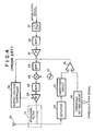
- Fig. 5 shows an arrangement example of a transmission power controller with such variable gain amplifier.
- Quadrature modulator 41 is used in CDMA because modulation methods such as QPSK and offset QPSK are employed, instead of VCXO in the mobile communication terminal equipment of the analog FM system.
- Quadrature modulator 41 has two base-band inputs: an in-phase component (I-signal); and a quadrature component (Q-signal). Quadrature modulator 41 modulates a local signal output from local oscillator 42 with the I-signal and Q-signal to generate an IF signal.
- I-signal in-phase component
- Q-signal quadrature component
- Band pass filter 43 restrained a bandwidth of the output signal of quadrature modulator 41 so as to eliminate undesired waves and obtain an IF signal with a desired frequency.
- Variable gain amplifier 44 amplifies the IF signal output from band pass filter 43.
- Band pass filter 45 restrains a bandwidth of the output signals from variable gain amplifier 44 to eliminate undesired waves and allows the IF signal with the desired frequency to pass through.
- Mixer 46 mixes the IF signal output from band pass filter 45 with a local signal output from local oscillator 47 to convert the IF signal into an RF signal.
- Band pass filter 48 restrains a bandwidth of the output signals from mixer 46 to eliminate undesired waves and allow an RF signal with a desired frequency to pass through.
- the RF signal output from band pass filter 48 is power-amplified at transmission power amplifier 49 and then radiated from antenna 50 as a transmission radio wave.
- the circuit of Fig. 5 does not use the ALC circuit unlike the case in Fig. 4. Instead, the circuit of Fig. 5 includes D/A converter 57 to generate a control voltage for variable gain amplifier 44 and controller 56 to set data for D/A converter 57.
- Two types of transmission power control which are an open loop power control and a closed loop power control, are performed in CDMA system.
- a mobile communication terminal equipment monitors the transmission power from a base station. If the transmission power is relatively higher, the mobile communication terminal equipment decides that the terminal locates near to the base station and lowers its own transmission power. If the transmission power from the base station is relatively lower, the mobile communication terminal equipment decides that the terminal locates far from the base station and elevates its own transmission power.
- a power control signal set in controller 56 at this moment by not depicted CPU of the mobile communication terminal equipment is called an open loop power control signal.
- the base station monitors the transmission power from the mobile communication terminal equipment.
- the base station transmits to the mobile communication terminal equipment a control signal for lowering the power if the transmission power is relatively higher and a control signal for elevating the power if the transmission power is relatively lower.
- the mobile communication terminal equipment periodically varies a control value of the transmission power by a certain variable amount such as 1 dB step in accordance with the control signal.
- a power control signal transmitted to the mobile communication terminal equipment from the base station is called a total power control signal.
- the open loop power control and closed loop power control are compossible in controller 56 which comprises up/down counter 61 as shown in Fig. 6.
- the aforementioned total power control signal is a signal of 1 bit. When the signal has a value of "1”, the signal instructs to elevate the transmission power. When the signal has a value of "0”, the signal instructs to lower the transmission power.
- the total power control signal is fed to U/DB terminal of up/down counter 61 through TPC (Total Power Control) terminal of controller 56.
- Up/down counter 61 counts periodically in synchronism with clocks fed to CK terminal and counts up or down when an input to U/DB terminal is "1" or "0". Up/down counter 61 outputs its count value as digital data from Dout terminal.
- D/A converter 57 converts the output data to an analog signal and outputs the analog signal as a control signal for variable gain amplifier 44.
- the control voltage output from D/A converter 57 controls the gain of variable gain amplifier 44, which in turn controls the transmission power of the mobile communication terminal equipment.
- Up/down counter 61 loads the open loop power control signal fed to Din terminal when a load signal is given to LOAD terminal and outputs as digital data from Dout terminal a count value corresponding to the control value of the power that is indicated with the control signal.
- D/A converter 57 converts the output data of controller 56 to an analog signal and outputs the analog signal as a control signal for variable gain amplifier 44 similarly to the above.
- the above-mentioned are the operations of a conventional transmission power controller in a mobile communication terminal equipment of the CDMA system.
- the transmission power controller of Fig. 5 causes the following disadvantages.
- the present invention has been made, and accordingly, has an object to provide a transmission power controller capable of suppressing an average transmission power below the maximum average transmission power stipulated under the Radio Related Law.
- the transmission power controller is adapted to a mobile communication terminal equipment which is required to control its transmission power with a relative precision (by 1 dB step and linear for dB) in a wide range (about 80 dB) to cope with to the Near-Far Problem in CDMA system, for example.
- a transmission power controller for use in mobile communication terminal equipment, comprising: a variable gain means arranged in a transmitter, for amplifying a transmission signal; a decision means for deciding whether an average transmission power from the mobile communication terminal equipment is higher or lower than an allowable maximum average transmission power; and a control means for controlling a gain of the variable gain means so as to lower a transmission power if the average transmission power is higher than the allowable maximum average transmission power.
- variable gain means may amplify an intermediate frequency signal, wherein the intermediate frequency signal is the transmission signal.
- the decision means may have an input-output characteristic with a hysteresis.
- the transmission power controller may further comprise: a means for transmitting a decided result of the decision means to a base station.
- a transmission power controller for use in a mobile communication terminal equipment, comprising: a variable gain means arranged in a transmitter, for amplifying a transmission signal; a detected voltage generating means for generating a detected voltage corresponding to an average transmission power from the mobile communication terminal equipment by detecting and smoothing a branched part of the output from a transmission power amplifier for amplifying a radio frequency signal; a threshold voltage generating means for generating a threshold voltage corresponding to an allowable maximum average transmission power; a decision means for deciding whether the average transmission power from the mobile communication terminal equipment is higher or lower than the allowable maximum average transmission power by comparing the detected voltage with the threshold voltage; and a control means for generating a control voltage to control a gain of the variable gain means, wherein the control means controls the control voltage so as to lower the gain of the variable gain means if the average transmission power is decided by the decision means to be higher than the allowable maximum average transmission power.
- variable gain means may amplify an intermediate frequency signal, wherein the intermediate frequency signal is the transmission signal.
- the decision means may have an input-output characteristic with a hysteresis.
- the transmission power controller according to the first and second aspect may further comprise: a means for transmitting a decided result of the decision means to a base station.
- a method for controlling a transmission power of a mobile communication terminal equipment comprising steps of: deciding whether an average transmission power from the mobile communication terminal equipment is higher or lower than an allowable maximum average transmission power; and controlling a gain of a variable gain means so as to lower a transmission power if the average transmission power is higher than the allowable maximum average transmission power, the variable gain means being arranged in a transmitter in the mobile communication terminal equipment and used for amplifying a transmission signal.
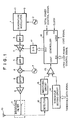
- Fig. 1 is a block diagram of a transmission power controller showing a first embodiment of the present invention.
- the transmission power controller of this embodiment is used for mobile communication terminal equipment in CDMA system.
- Quadrature modulator 1 is used in CDMA because modulation methods such as QPSK (Quadriphase Phase Shift Keying) and offset QPSK are employed, instead of VCXO in the mobile communication terminal equipment of the analog FM system.
- Quadrature modulator 1 has two base-band inputs: an in-phase component (I-signal); and a quadrature component (Q-signal). Quadrature modulator 1 modulates a local signal output from local oscillator 2 with the I-signal and Q-signal to generate an IF signal.
- I-signal in-phase component
- Q-signal quadrature component
- Band pass filter 3 restrains a bandwidth of the output signal of quadrature modulator 1 which passes therethrough, so as to eliminate undesired waves thereof and obtain an IF signal with a desired frequency.
- Variable gain amplifier 4 amplifies the IF signal output from band pass filter 3.
- Band pass filter 5 restrains a bandwidth of the output signal from variable gain amplifier 4 to eliminate undesired waves and allows an IF signal with a desired frequency to pass through. Gain control for variable gain amplifier 4 will be explained later.
- Mixer 6 mixes the IF signal output from band pass filter 5 with a local signal output from local oscillator 7 to convert the IF signal to a RF signal.
- Band pass filter 8 restrains a bandwidth of the output signals from mixer 6 to eliminate undesired waves and allow an RF signal with a desired frequency to pass through.
- the RF signal output from band pass filter 8 is power-amplified at transmission power amplifier 9 and then radiated from antenna 10 as a transmission radio wave.
- Branching filter 11 partly separates the output signal from transmission power amplifier 9.
- Detector 12 detects the output signal from transmission power amplifier 9 separated by branching filter 11.
- Smoothing circuit 13 smoothes the output signal from detector 12.
- a DC voltage (hereinafter referred to as a detected voltage) corresponding to an average transmission power from the mobile communication terminal equipment including the transmission power controller in Fig. 1.
- Detector 12 comprises a Shottky barrier diode, for example.
- Smoothing circuit 13 comprises a low pass filter consisting of coils and capacitors.
- Smoothing circuit 13 may also comprise an active low pass filter consisting of an operational amplifier and capacitors in order to obtain the detected voltage corresponding to a long-term average transmission power.
- Threshold setting circuit 14 outputs on the basis of a threshold data signal a threshold voltage corresponding to the maximum average transmission power stipulated under the Radio Related Law.
- Threshold setting circuit 14 comprises a D/A converter, for example.
- Threshold setting circuit 14 receives the threshold data signal corresponding to the maximum average transmission power from CPU (not depicted) and outputs a DC voltage obtained by converting the threshold data signal from digital to analog, which is the threshold voltage.
- Threshold setting circuit 14 can also be realized by a simple arrangement that divides the supply voltage with a variable resistor and the like. The threshold data signal is not required in this case.
- Voltage comparator 15 compares the detected voltage output from smoothing circuit 13 with the threshold voltage output from threshold setting circuit 14. The detected voltage is applied to the inverting input terminal of voltage comparator 15 and the threshold voltage is applied to the non-inverting input terminal thereof in this embodiment.
- Controller 16 and D/A converter 17 will be explained next.
- Two types of transmission power control which are an open loop power control and a closed loop power control, are performed in CDMA system.
- the mobile communication terminal equipment monitors the transmission power from the base station. If the transmission power is relatively higher, the mobile communication terminal equipment decides that the terminal locates near to the base station and lowers its own transmission power. If the transmission power from the base station is relatively lower, the mobile communication terminal equipment decides that the terminal locates far from the base station and elevates its own transmission power. (A power control signal set in controller 16 by not depicted CPU of the mobile communication terminal equipment is called an open loop power control signal).
- the base station monitors the transmission power from the mobile communication terminal equipment.
- the base station transmits to the mobile communication terminal equipment a control signal for lowering the transmission power if the transmission power is relatively higher and a control signal for elevating the transmission power if the transmission power is relatively lower.
- the mobile communication terminal equipment varies periodically a control value of the transmission power by a certain variable amount such as 1 dB step in accordance with the control signal. (A power control signal transmitted to the mobile communication terminal equipment from the base station is called a total power control signal.)
- the open loop power control and the closed loop power control, and the transmission power control according to the present invention based on the result obtained by comparing the detected voltage with the threshold voltage are compossible in controller 16.
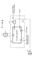
- the controller comprises up/down counter 61 and AND gate 62 as shown in Fig. 2.
- the total power control signal is a signal consisting of 1 bit received from the base station at a receiving means (not depicted) in the mobile communication terminal equipment. When the signal has a value of "1”, the signal instructs to elevate the transmission power. When the signal has a value of "0”, the signal instructs to lower the transmission power.
- the total power control signal is fed to one input terminal of AND gate 62 through the TPC terminal of controller 16.
- Up/down counter 61 counts periodically in synchronism with clocks fed to CK terminal and counts up or down when an input to U/DB terminal for alternating up-count and down-count is "1" or "0".
- a function for preventing overflow or underflow of counter 61 when counter 61 continuously count up or down is of course necessary, however, it is not related directly to the present invention and an explanation thereof is omitted.
- Up/down counter 61 outputs its count value as digital data consisting of plural bits from Dout terminal.
- D/A converter 17 converts the output data of controller 16 (or up/down counter 61) from digital to analog and outputs the converted result as a control signal for variable gain amplifier 4.
- the control voltage output from D/A converter 17 controls the gain of variable gain amplifier 4, which in turn controls the transmission power of the mobile communication terminal equipment.
- Up/down counter 61 loads the open loop power control signal consisting of plural bits fed to Din terminal when a load signal is given to LOAD terminal, and outputs as digital data consisting of plural bits from Dout terminal a count value corresponding to the control value of the power indicated with the control signal.
- D/A converter 17 converts the output data of controller 16 from digital to analog and outputs the control signal for variable gain amplifier 4 similarly to the above.
- the output signal from voltage comparator 15 is fed to the other input terminal of AND gate 62 through CONT terminal of controller 15 in this embodiment.
- AND gate 62 makes a logical product of the total power control signal and the output signal from voltage comparator 15.
- the output signal of AND gate 62 is supplied to U/DB terminal of up/down counter 61.
- the output signal of voltage comparator 15 becomes "0" as described above. To the contrary, if the average transmission power is lower than the allowable maximum average transmission power, the output signal of voltage comparator 15 becomes "1".
- the open loop power control based on the open loop power control signal and the closed loop power control based on the total power control signal, and the transmission power control according to the present invention based on the result obtained by comparing the detected voltage (the average transmission power) with the threshold voltage (the allowable maximum average transmission power) are compossible. It is possible to operate so as to compulsorily lower the transmission power, if the average transmission power of the mobile communication terminal equipment is higher than the allowable maximum average transmission power, while ignoring the open loop power control and the closed loop power control.
- both the transmission power of the mobile communication terminal equipment monitored at the base station and the transmission power of the base station monitored at the mobile communication terminal equipment become low. Then, the base station transmits the total power control signal instructing to increasing the transmission power and the mobile communication terminal equipment also generates from its CPU the open loop power control signal instructing to increasing the transmission power. Therefore, the closed loop power control and open loop power control both perform the transmission power control in the same direction in this case.
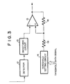
- Fig. 3 is a block diagram of a transmission power controller showing a second embodiment of the present invention, in which the same reference numerals are given to the same parts as those shown in Fig. 1. Fig. 3 only shows parts different from the transmission power controller shown in Fig. 1.
- the transmission power controller of this embodiment has a arrangement fundamentally similar to that of the first embodiment.
- This embodiment gives a hysteresis to voltage comparator 15 in order to prevent the decided result from hunting.
- Resistors 18 and 19 for positively feeding the output of voltage comparator 15 back to the threshold voltage side are added to the circuit in Fig. 1 in order to give the hysteresis to voltage comparator 15.
- the output signal of voltage comparator 15 (that is a result obtained by comparing the detected voltage with the threshold voltage) may be detected by a detecting means such as a CPU not depicted, and the detected result can be transmitted to the base station.
- a detecting means such as a CPU not depicted
- the detected result from the detecting means is converted into an I-signal and/or a Q-signal which are to be fed to quadrature modulator 1.
- the base station can recognize whether or not the average transmission power of the mobile communication terminal equipment exceeds the maximum average transmission power accordingly.
- the average transmission power of the mobile communication terminal equipment exceeds the maximum average transmission power, it is also possible to control the mobile communication terminal equipment by instructing to reduce the transmission power with the total power control signal transmitted from the base station.
- Variable gain amplifier 4 may be arranged at a location where the RF or base-band signal is amplified although it is arranged at the location where the IF signal is amplified in the above embodiments.
- variable gain means is arranged in the transmitter and the decision means and control means are also employed.
- the transmission power is compulsorily lowered, if the average transmission power of the mobile communication terminal equipment is higher than the allowable maximum average transmission power, while ignoring the open loop power control and closed loop power control.
- the transmission power control with a wide dynamic range and relative high-precision to cope with a CDMA system and the like can be compossible with the transmission power control to prevent the average transmission power from exceeding the maximum average transmission power stipulated under the Radio Related Law.
- Giving the input-output characteristic with the hysteresis to the decision means may prevent the decided result from hunting.
- Providing the means for transmitting the decided result of the decision means to the base station may notify the base station whether or not the average transmission power of the mobile communication terminal equipment exceeds the maximum average transmission power. The base station can then control the transmission power of the mobile communication terminal equipment based on the notification.
Landscapes
- Engineering & Computer Science (AREA)
- Computer Networks & Wireless Communication (AREA)
- Signal Processing (AREA)
- Transmitters (AREA)
- Mobile Radio Communication Systems (AREA)
Applications Claiming Priority (2)
| Application Number | Priority Date | Filing Date | Title |
|---|---|---|---|
| JP21085698 | 1998-07-27 | ||
| JP21085698A JP3240998B2 (ja) | 1998-07-27 | 1998-07-27 | 送信パワー制御回路 |
Publications (3)
| Publication Number | Publication Date |
|---|---|
| EP0989689A2 true EP0989689A2 (fr) | 2000-03-29 |
| EP0989689A3 EP0989689A3 (fr) | 2000-04-12 |
| EP0989689B1 EP0989689B1 (fr) | 2007-09-12 |
Family
ID=16596243
Family Applications (1)
| Application Number | Title | Priority Date | Filing Date |
|---|---|---|---|
| EP99114086A Expired - Lifetime EP0989689B1 (fr) | 1998-07-27 | 1999-07-20 | Contrôleur de puissance de transmission pour utilisation dans un poste terminal de communication mobile |
Country Status (6)
| Country | Link |
|---|---|
| US (1) | US6330455B1 (fr) |
| EP (1) | EP0989689B1 (fr) |
| JP (1) | JP3240998B2 (fr) |
| KR (1) | KR100375902B1 (fr) |
| CN (1) | CN1152475C (fr) |
| DE (1) | DE69937093T2 (fr) |
Cited By (3)
| Publication number | Priority date | Publication date | Assignee | Title |
|---|---|---|---|---|
| WO2001033733A3 (fr) * | 1999-11-03 | 2001-09-27 | Koninkl Philips Electronics Nv | Reglage de puissance dans une station de transmission d'un systeme de communication |
| US7177659B2 (en) * | 2002-10-16 | 2007-02-13 | Lg Electronics Inc. | Power amplification system and method |
| US7194282B2 (en) | 2001-12-20 | 2007-03-20 | Nokia Corporation | Method for controlling transmitting power in a wireless communication device |
Families Citing this family (48)
| Publication number | Priority date | Publication date | Assignee | Title |
|---|---|---|---|---|
| JP3499448B2 (ja) * | 1998-08-28 | 2004-02-23 | 松下電器産業株式会社 | 無線通信端末装置及び送信電力制御方法 |
| US7295855B1 (en) * | 2000-03-10 | 2007-11-13 | Denso Corporation | Transmit power reduction mode for CDMA mobile stations |
| US6684064B2 (en) * | 2000-03-29 | 2004-01-27 | Interdigital Technology Corp. | Dynamic bias for RF power amplifiers |
| US6825719B1 (en) * | 2000-05-26 | 2004-11-30 | Intel Corporation | RF power amplifier and methods for improving the efficiency thereof |
| CA2315123C (fr) * | 2000-08-04 | 2011-07-05 | Mine Radio Systems Inc. | Systeme informatique de reseau local se servant d'une ligne de transmission rayonnante |
| US7567781B2 (en) | 2001-01-05 | 2009-07-28 | Qualcomm, Incorporated | Method and apparatus for power level adjustment in a wireless communication system |
| US7945266B2 (en) | 2000-12-05 | 2011-05-17 | Qualcomm Incorporated | Method and apparatus for call recovery in a wireless communication system |
| US6587511B2 (en) * | 2001-01-26 | 2003-07-01 | Intel Corporation | Radio frequency transmitter and methods thereof |
| US7570709B2 (en) * | 2001-03-08 | 2009-08-04 | Siemens Aktiengesellschaft | Automatic transmit power control loop with modulation averaging |
| KR100415821B1 (ko) * | 2001-06-29 | 2004-01-24 | 삼성전자주식회사 | 히트 싱크를 구비한 전력반도체 모듈 |
| US20030125065A1 (en) * | 2001-12-27 | 2003-07-03 | Ilan Barak | Method and apparatus for generating an output signal |
| US20030123566A1 (en) * | 2001-12-27 | 2003-07-03 | Jaime Hasson | Transmitter having a sigma-delta modulator with a non-uniform polar quantizer and methods thereof |
| JP3958066B2 (ja) * | 2002-02-21 | 2007-08-15 | ソニー・エリクソン・モバイルコミュニケーションズ株式会社 | 送信出力回路および移動体通信端末 |
| US20040203984A1 (en) * | 2002-06-11 | 2004-10-14 | Tai-Her Yang | Wireless information device with its transmission power lever adjustable |
| JP4133019B2 (ja) * | 2002-06-21 | 2008-08-13 | 日産ディーゼル工業株式会社 | 車両の蓄電制御装置 |
| JP3970177B2 (ja) * | 2002-12-26 | 2007-09-05 | パナソニック モバイルコミュニケーションズ株式会社 | 無線通信装置 |
| US7336753B2 (en) * | 2003-06-26 | 2008-02-26 | Marvell International Ltd. | Transmitter |
| ATE327601T1 (de) * | 2003-10-23 | 2006-06-15 | Sony Ericsson Mobile Comm Ab | Zusätzliche regelung des referenzsignals der automatischen leistungsregelung in einem mobilen endgerät |
| US7912145B2 (en) * | 2003-12-15 | 2011-03-22 | Marvell World Trade Ltd. | Filter for a modulator and methods thereof |
| US7356315B2 (en) * | 2003-12-17 | 2008-04-08 | Intel Corporation | Outphasing modulators and methods of outphasing modulation |
| KR100641158B1 (ko) * | 2004-07-10 | 2006-11-06 | 엘지전자 주식회사 | 이동 통신 단말기의 송신 출력 제어 방법 |
| JP4343952B2 (ja) * | 2004-07-30 | 2009-10-14 | 京セラ株式会社 | 無線通信端末及びこの制御方法 |
| JP4656387B2 (ja) | 2004-12-28 | 2011-03-23 | 日本電気株式会社 | 移動無線通信システム、及び移動無線通信システムにおける監視制御方法 |
| US7430403B2 (en) * | 2005-03-01 | 2008-09-30 | Matsushita Electric Industrial Co., Ltd. | Method and apparatus for hysteresis control |
| JP4713923B2 (ja) * | 2005-04-15 | 2011-06-29 | 株式会社エヌ・ティ・ティ・ドコモ | 無線通信制御システム、無線基地局及び無線通信制御方法 |
| JP4673147B2 (ja) * | 2005-06-24 | 2011-04-20 | 日本電信電話株式会社 | 情報漏洩防止信号出力の制御方法及び情報漏洩防止信号出力の制御装置 |
| JP4673148B2 (ja) * | 2005-06-28 | 2011-04-20 | 日本電信電話株式会社 | 入力情報漏洩防止装置 |
| US8559896B2 (en) * | 2005-06-30 | 2013-10-15 | Harris Stratex Networks, Inc. | System and method for radio power level control |
| JP4633592B2 (ja) * | 2005-09-28 | 2011-02-16 | 京セラ株式会社 | 無線通信端末 |
| CA2625685C (fr) * | 2005-10-14 | 2012-04-24 | Research In Motion Limited | Systeme et procede pour gerer un effondrement de la puissance d'accumulateurs |
| CN101009714B (zh) * | 2006-01-27 | 2012-08-08 | 马维尔国际贸易有限公司 | 可变功率适应性发射器 |
| US8396511B2 (en) * | 2007-02-28 | 2013-03-12 | Samsung Electronics Co., Ltd. | Apparatus and method for determining an uplink transmission format in a broadband wireless communication system |
| JP4383480B2 (ja) * | 2007-11-15 | 2009-12-16 | 株式会社エヌ・ティ・ティ・ドコモ | 移動通信端末及び移動通信端末における送信電力制御方法 |
| KR101263893B1 (ko) | 2008-05-28 | 2013-05-13 | 삼성전자주식회사 | 인체 통신 시스템에서 송신 전력을 제어하기 위한 장치 및방법 |
| US8275407B2 (en) * | 2009-07-24 | 2012-09-25 | Qualcomm Incorporated | Methods and apparatus for communicating using multiple transmission power levels |
| CN102033555B (zh) * | 2010-12-17 | 2014-07-16 | 中兴通讯股份有限公司 | 一种lte系统中功放电压调节方法及装置 |
| EP2850887A1 (fr) * | 2012-05-07 | 2015-03-25 | Telefonaktiebolaget LM Ericsson (PUBL) | Procédés et agencements de commande de puissance d'émission dans une station de base radio |
| US9419457B2 (en) | 2012-09-04 | 2016-08-16 | Google Technology Holdings LLC | Method and device with enhanced battery capacity savings |
| CN103684533A (zh) * | 2012-09-17 | 2014-03-26 | 深圳市云通时代科技开发有限公司 | 蓝牙通信距离调整方法及蓝牙中继网关 |
| US9356461B2 (en) | 2012-09-25 | 2016-05-31 | Google Technology Holdings, LLC | Methods and systems for rapid wireless charging where the low state of charge (SOC) temperature dependent charging current and low SOC temperature limit are higher than the high SOC temperature dependent charging current and high SOC temperature limit |
| US9491706B2 (en) | 2013-03-13 | 2016-11-08 | Google Technology Holdings LLC | Reduced-power transmitting from a communications device |
| US9596653B2 (en) | 2013-12-16 | 2017-03-14 | Google Technology Holdings LLC | Remedying power drain via a coverage map |
| CN103684550B (zh) * | 2013-12-20 | 2018-01-02 | 上海斐讯数据通信技术有限公司 | 一种蓝牙信号发射功率调整系统及移动终端 |
| US9865897B2 (en) | 2014-06-02 | 2018-01-09 | Google Llc | Stacked electrochemical cell with increased energy density |
| US9438293B2 (en) | 2014-08-05 | 2016-09-06 | Google Technology Holdings LLC | Tunable circuit elements for dynamic, per element power |
| US9472965B2 (en) | 2014-09-08 | 2016-10-18 | Google Technology Holdings LLC | Battery cycle life through smart overnight charging |
| CN113176510A (zh) * | 2021-04-02 | 2021-07-27 | 深圳力维智联技术有限公司 | 铅酸电池放电过程中电压极值的预测方法、装置及设备 |
| CN120322972A (zh) | 2022-12-19 | 2025-07-15 | 三星电子株式会社 | 用于在时分双工方案中放大发送信号的电子设备和方法 |
Family Cites Families (16)
| Publication number | Priority date | Publication date | Assignee | Title |
|---|---|---|---|---|
| JPS56106431A (en) | 1980-01-25 | 1981-08-24 | Matsushita Electric Ind Co Ltd | Transistor of reduced carrier ssb signal |
| JPH02217011A (ja) | 1989-02-17 | 1990-08-29 | Nec Corp | 送信装置の送信電力制御回路 |
| US5265119A (en) * | 1989-11-07 | 1993-11-23 | Qualcomm Incorporated | Method and apparatus for controlling transmission power in a CDMA cellular mobile telephone system |
| JP3126426B2 (ja) | 1990-07-27 | 2001-01-22 | 株式会社東芝 | 自動電力制御装置及び自動電力制御機能を備えた無線通信装置 |
| KR950000054B1 (ko) * | 1990-07-27 | 1995-01-07 | 가부시끼가이샤 도시바 | 자동파워 콘트롤장치 |
| US5129098A (en) * | 1990-09-24 | 1992-07-07 | Novatel Communication Ltd. | Radio telephone using received signal strength in controlling transmission power |
| US5128629A (en) * | 1991-04-22 | 1992-07-07 | Hughes Aircraft Company | Method for controlling the output power of digital cellular telephones |
| US5287555A (en) * | 1991-07-22 | 1994-02-15 | Motorola, Inc. | Power control circuitry for a TDMA radio frequency transmitter |
| FI96554C (fi) * | 1993-02-05 | 1996-07-10 | Nokia Mobile Phones Ltd | Aikajakoinen solukkoradiopuhelinjärjestelmä ja radiopuhelin sitä varten |
| US5452473A (en) | 1994-02-28 | 1995-09-19 | Qualcomm Incorporated | Reverse link, transmit power correction and limitation in a radiotelephone system |
| JP2980156B2 (ja) * | 1994-05-12 | 1999-11-22 | エヌ・ティ・ティ移動通信網株式会社 | 送信電力制御方法および該制御方法を用いたスペクトル拡散通信装置 |
| JP2974274B2 (ja) * | 1994-05-12 | 1999-11-10 | エヌ・ティ・ティ移動通信網株式会社 | 送信電力制御方法および送信電力制御装置 |
| JP2993554B2 (ja) | 1994-05-12 | 1999-12-20 | エヌ・ティ・ティ移動通信網株式会社 | 送信電力制御法および前記送信電力制御法を用いた通信装置 |
| US5548616A (en) * | 1994-09-09 | 1996-08-20 | Nokia Mobile Phones Ltd. | Spread spectrum radiotelephone having adaptive transmitter gain control |
| JPH08325515A (ja) | 1995-06-05 | 1996-12-10 | Nippon Shokubai Co Ltd | 水溶性保護コーティング剤およびそれを用いたコーティング方法 |
| JPH1022756A (ja) * | 1996-07-04 | 1998-01-23 | Mitsubishi Electric Corp | 無線送信機およびその送信制御方法 |
-
1998
- 1998-07-27 JP JP21085698A patent/JP3240998B2/ja not_active Expired - Lifetime
-
1999
- 1999-07-20 DE DE69937093T patent/DE69937093T2/de not_active Expired - Lifetime
- 1999-07-20 EP EP99114086A patent/EP0989689B1/fr not_active Expired - Lifetime
- 1999-07-24 KR KR10-1999-0030160A patent/KR100375902B1/ko not_active Expired - Fee Related
- 1999-07-26 US US09/360,610 patent/US6330455B1/en not_active Expired - Lifetime
- 1999-07-27 CN CNB991111427A patent/CN1152475C/zh not_active Expired - Lifetime
Cited By (3)
| Publication number | Priority date | Publication date | Assignee | Title |
|---|---|---|---|---|
| WO2001033733A3 (fr) * | 1999-11-03 | 2001-09-27 | Koninkl Philips Electronics Nv | Reglage de puissance dans une station de transmission d'un systeme de communication |
| US7194282B2 (en) | 2001-12-20 | 2007-03-20 | Nokia Corporation | Method for controlling transmitting power in a wireless communication device |
| US7177659B2 (en) * | 2002-10-16 | 2007-02-13 | Lg Electronics Inc. | Power amplification system and method |
Also Published As
| Publication number | Publication date |
|---|---|
| JP3240998B2 (ja) | 2001-12-25 |
| KR100375902B1 (ko) | 2003-03-15 |
| DE69937093T2 (de) | 2008-06-12 |
| JP2000049629A (ja) | 2000-02-18 |
| CN1248104A (zh) | 2000-03-22 |
| KR20000011950A (ko) | 2000-02-25 |
| DE69937093D1 (de) | 2007-10-25 |
| EP0989689A3 (fr) | 2000-04-12 |
| US6330455B1 (en) | 2001-12-11 |
| EP0989689B1 (fr) | 2007-09-12 |
| CN1152475C (zh) | 2004-06-02 |
Similar Documents
| Publication | Publication Date | Title |
|---|---|---|
| EP0989689B1 (fr) | Contrôleur de puissance de transmission pour utilisation dans un poste terminal de communication mobile | |
| EP1902525B1 (fr) | Emetteur radiofrequence (rf) a boucle polaire presentant un reglage d'amplitude a gamme dynamique etendue | |
| US7177607B2 (en) | Controlling transmission mode on basis of power in preceding time slot | |
| EP1526651B1 (fr) | Régulation additionnelle du signal de référence de la commande automatique de la puissance dans un terminal mobile | |
| AU643623B2 (en) | Power amplifier ramp up method and apparatus | |
| AU674475B2 (en) | Method and apparatus for correction and limitation of transmitter power on the reverse link of a mobile radio telephone system | |
| EP1755214B1 (fr) | Amplificateur de puissance à haute fréquence pour appareil de communication sans fil | |
| US6011980A (en) | Wireless telecommunication equipment | |
| EP0961402B1 (fr) | Un émetteur | |
| US6718165B1 (en) | Apparatus and method for reducing nonlinear distortion in an automatic gain control system | |
| US8160630B2 (en) | Method and arrangement for controlling transmission power and a network element | |
| WO1996033555A1 (fr) | Commande de gain automatique a compensation de temperature | |
| EP1026833B1 (fr) | Terminal mobile portable et unité d'émission avec commande de la puissance | |
| JP2001086010A (ja) | 送信パワー補正回路 | |
| US6057732A (en) | Transmission power control circuit and method for CDMA system | |
| KR101050928B1 (ko) | 무선 통신 장치의 qam 송신기 유닛을 위한 자동 전력제어 회로 | |
| US6484017B1 (en) | Up converter of base station transmitter in wireless communication system and method of controlling outputs thereof | |
| JP4023025B2 (ja) | 無線通信装置及び無線通信装置の送信電力制御方法 | |
| KR100407939B1 (ko) | 이동 통신 기지국에서 업 컨버터의 자동 이득 제어 장치 | |
| KR20040061801A (ko) | 전력 검파기를 이용한 송신전력 제어장치 및 그 방법 | |
| JP2004032447A (ja) | 無線装置の送信機とその送信レベル制御方法 | |
| EP1751943A1 (fr) | Emetteur et procede de fonctionnement d'un emetteur |
Legal Events
| Date | Code | Title | Description |
|---|---|---|---|
| PUAI | Public reference made under article 153(3) epc to a published international application that has entered the european phase |
Free format text: ORIGINAL CODE: 0009012 |
|
| PUAL | Search report despatched |
Free format text: ORIGINAL CODE: 0009013 |
|
| AK | Designated contracting states |
Kind code of ref document: A2 Designated state(s): DE FR GB IT NL |
|
| AX | Request for extension of the european patent |
Free format text: AL;LT;LV;MK;RO;SI |
|
| AK | Designated contracting states |
Kind code of ref document: A3 Designated state(s): AT BE CH CY DE DK ES FI FR GB GR IE IT LI LU MC NL PT SE |
|
| AX | Request for extension of the european patent |
Free format text: AL;LT;LV;MK;RO;SI |
|
| 17P | Request for examination filed |
Effective date: 20000728 |
|
| AKX | Designation fees paid |
Free format text: DE FR GB IT NL |
|
| 17Q | First examination report despatched |
Effective date: 20040628 |
|
| GRAP | Despatch of communication of intention to grant a patent |
Free format text: ORIGINAL CODE: EPIDOSNIGR1 |
|
| GRAS | Grant fee paid |
Free format text: ORIGINAL CODE: EPIDOSNIGR3 |
|
| GRAA | (expected) grant |
Free format text: ORIGINAL CODE: 0009210 |
|
| AK | Designated contracting states |
Kind code of ref document: B1 Designated state(s): DE FR GB IT NL |
|
| REG | Reference to a national code |
Ref country code: GB Ref legal event code: FG4D |
|
| REF | Corresponds to: |
Ref document number: 69937093 Country of ref document: DE Date of ref document: 20071025 Kind code of ref document: P |
|
| NLV1 | Nl: lapsed or annulled due to failure to fulfill the requirements of art. 29p and 29m of the patents act | ||
| ET | Fr: translation filed | ||
| PG25 | Lapsed in a contracting state [announced via postgrant information from national office to epo] |
Ref country code: NL Free format text: LAPSE BECAUSE OF FAILURE TO SUBMIT A TRANSLATION OF THE DESCRIPTION OR TO PAY THE FEE WITHIN THE PRESCRIBED TIME-LIMIT Effective date: 20070912 |
|
| PLBE | No opposition filed within time limit |
Free format text: ORIGINAL CODE: 0009261 |
|
| STAA | Information on the status of an ep patent application or granted ep patent |
Free format text: STATUS: NO OPPOSITION FILED WITHIN TIME LIMIT |
|
| 26N | No opposition filed |
Effective date: 20080613 |
|
| REG | Reference to a national code |
Ref country code: FR Ref legal event code: PLFP Year of fee payment: 18 |
|
| REG | Reference to a national code |
Ref country code: FR Ref legal event code: PLFP Year of fee payment: 19 |
|
| REG | Reference to a national code |
Ref country code: FR Ref legal event code: PLFP Year of fee payment: 20 |
|
| PGFP | Annual fee paid to national office [announced via postgrant information from national office to epo] |
Ref country code: FR Payment date: 20180612 Year of fee payment: 20 |
|
| PGFP | Annual fee paid to national office [announced via postgrant information from national office to epo] |
Ref country code: IT Payment date: 20180713 Year of fee payment: 20 Ref country code: DE Payment date: 20180710 Year of fee payment: 20 |
|
| PGFP | Annual fee paid to national office [announced via postgrant information from national office to epo] |
Ref country code: GB Payment date: 20180718 Year of fee payment: 20 |
|
| REG | Reference to a national code |
Ref country code: DE Ref legal event code: R071 Ref document number: 69937093 Country of ref document: DE |
|
| REG | Reference to a national code |
Ref country code: GB Ref legal event code: PE20 Expiry date: 20190719 |
|
| PG25 | Lapsed in a contracting state [announced via postgrant information from national office to epo] |
Ref country code: GB Free format text: LAPSE BECAUSE OF EXPIRATION OF PROTECTION Effective date: 20190719 |