EP0989830B1 - Intravaskulärer stent mit einer ablenkvorrichtung - Google Patents
Intravaskulärer stent mit einer ablenkvorrichtung Download PDFInfo
- Publication number
- EP0989830B1 EP0989830B1 EP98924506A EP98924506A EP0989830B1 EP 0989830 B1 EP0989830 B1 EP 0989830B1 EP 98924506 A EP98924506 A EP 98924506A EP 98924506 A EP98924506 A EP 98924506A EP 0989830 B1 EP0989830 B1 EP 0989830B1
- Authority
- EP
- European Patent Office
- Prior art keywords
- deflector
- artery
- stent according
- stent
- wall
- Prior art date
- Legal status (The legal status is an assumption and is not a legal conclusion. Google has not performed a legal analysis and makes no representation as to the accuracy of the status listed.)
- Expired - Lifetime
Links
Images

Classifications
-
- A—HUMAN NECESSITIES
- A61—MEDICAL OR VETERINARY SCIENCE; HYGIENE
- A61F—FILTERS IMPLANTABLE INTO BLOOD VESSELS; PROSTHESES; DEVICES PROVIDING PATENCY TO, OR PREVENTING COLLAPSING OF, TUBULAR STRUCTURES OF THE BODY, e.g. STENTS; ORTHOPAEDIC, NURSING OR CONTRACEPTIVE DEVICES; FOMENTATION; TREATMENT OR PROTECTION OF EYES OR EARS; BANDAGES, DRESSINGS OR ABSORBENT PADS; FIRST-AID KITS
- A61F2/00—Filters implantable into blood vessels; Prostheses, i.e. artificial substitutes or replacements for parts of the body; Appliances for connecting them with the body; Devices providing patency to, or preventing collapsing of, tubular structures of the body, e.g. stents
- A61F2/82—Devices providing patency to, or preventing collapsing of, tubular structures of the body, e.g. stents
- A61F2/86—Stents in a form characterised by the wire-like elements; Stents in the form characterised by a net-like or mesh-like structure
-
- A—HUMAN NECESSITIES
- A61—MEDICAL OR VETERINARY SCIENCE; HYGIENE
- A61F—FILTERS IMPLANTABLE INTO BLOOD VESSELS; PROSTHESES; DEVICES PROVIDING PATENCY TO, OR PREVENTING COLLAPSING OF, TUBULAR STRUCTURES OF THE BODY, e.g. STENTS; ORTHOPAEDIC, NURSING OR CONTRACEPTIVE DEVICES; FOMENTATION; TREATMENT OR PROTECTION OF EYES OR EARS; BANDAGES, DRESSINGS OR ABSORBENT PADS; FIRST-AID KITS
- A61F2/00—Filters implantable into blood vessels; Prostheses, i.e. artificial substitutes or replacements for parts of the body; Appliances for connecting them with the body; Devices providing patency to, or preventing collapsing of, tubular structures of the body, e.g. stents
- A61F2/01—Filters implantable into blood vessels
- A61F2002/016—Filters implantable into blood vessels made from wire-like elements
-
- A—HUMAN NECESSITIES
- A61—MEDICAL OR VETERINARY SCIENCE; HYGIENE
- A61F—FILTERS IMPLANTABLE INTO BLOOD VESSELS; PROSTHESES; DEVICES PROVIDING PATENCY TO, OR PREVENTING COLLAPSING OF, TUBULAR STRUCTURES OF THE BODY, e.g. STENTS; ORTHOPAEDIC, NURSING OR CONTRACEPTIVE DEVICES; FOMENTATION; TREATMENT OR PROTECTION OF EYES OR EARS; BANDAGES, DRESSINGS OR ABSORBENT PADS; FIRST-AID KITS
- A61F2/00—Filters implantable into blood vessels; Prostheses, i.e. artificial substitutes or replacements for parts of the body; Appliances for connecting them with the body; Devices providing patency to, or preventing collapsing of, tubular structures of the body, e.g. stents
- A61F2/02—Prostheses implantable into the body
- A61F2/04—Hollow or tubular parts of organs, e.g. bladders, tracheae, bronchi or bile ducts
- A61F2/06—Blood vessels
- A61F2002/068—Modifying the blood flow model, e.g. by diffuser or deflector
-
- A—HUMAN NECESSITIES
- A61—MEDICAL OR VETERINARY SCIENCE; HYGIENE
- A61F—FILTERS IMPLANTABLE INTO BLOOD VESSELS; PROSTHESES; DEVICES PROVIDING PATENCY TO, OR PREVENTING COLLAPSING OF, TUBULAR STRUCTURES OF THE BODY, e.g. STENTS; ORTHOPAEDIC, NURSING OR CONTRACEPTIVE DEVICES; FOMENTATION; TREATMENT OR PROTECTION OF EYES OR EARS; BANDAGES, DRESSINGS OR ABSORBENT PADS; FIRST-AID KITS
- A61F2210/00—Particular material properties of prostheses classified in groups A61F2/00 - A61F2/26 or A61F2/82 or A61F9/00 or A61F11/00 or subgroups thereof
- A61F2210/0004—Particular material properties of prostheses classified in groups A61F2/00 - A61F2/26 or A61F2/82 or A61F9/00 or A61F11/00 or subgroups thereof bioabsorbable
-
- A—HUMAN NECESSITIES
- A61—MEDICAL OR VETERINARY SCIENCE; HYGIENE
- A61F—FILTERS IMPLANTABLE INTO BLOOD VESSELS; PROSTHESES; DEVICES PROVIDING PATENCY TO, OR PREVENTING COLLAPSING OF, TUBULAR STRUCTURES OF THE BODY, e.g. STENTS; ORTHOPAEDIC, NURSING OR CONTRACEPTIVE DEVICES; FOMENTATION; TREATMENT OR PROTECTION OF EYES OR EARS; BANDAGES, DRESSINGS OR ABSORBENT PADS; FIRST-AID KITS
- A61F2210/00—Particular material properties of prostheses classified in groups A61F2/00 - A61F2/26 or A61F2/82 or A61F9/00 or A61F11/00 or subgroups thereof
- A61F2210/0095—Particular material properties of prostheses classified in groups A61F2/00 - A61F2/26 or A61F2/82 or A61F9/00 or A61F11/00 or subgroups thereof radioactive
-
- A—HUMAN NECESSITIES
- A61—MEDICAL OR VETERINARY SCIENCE; HYGIENE
- A61F—FILTERS IMPLANTABLE INTO BLOOD VESSELS; PROSTHESES; DEVICES PROVIDING PATENCY TO, OR PREVENTING COLLAPSING OF, TUBULAR STRUCTURES OF THE BODY, e.g. STENTS; ORTHOPAEDIC, NURSING OR CONTRACEPTIVE DEVICES; FOMENTATION; TREATMENT OR PROTECTION OF EYES OR EARS; BANDAGES, DRESSINGS OR ABSORBENT PADS; FIRST-AID KITS
- A61F2230/00—Geometry of prostheses classified in groups A61F2/00 - A61F2/26 or A61F2/82 or A61F9/00 or A61F11/00 or subgroups thereof
- A61F2230/0002—Two-dimensional shapes, e.g. cross-sections
- A61F2230/0004—Rounded shapes, e.g. with rounded corners
- A61F2230/0006—Rounded shapes, e.g. with rounded corners circular
-
- A—HUMAN NECESSITIES
- A61—MEDICAL OR VETERINARY SCIENCE; HYGIENE
- A61F—FILTERS IMPLANTABLE INTO BLOOD VESSELS; PROSTHESES; DEVICES PROVIDING PATENCY TO, OR PREVENTING COLLAPSING OF, TUBULAR STRUCTURES OF THE BODY, e.g. STENTS; ORTHOPAEDIC, NURSING OR CONTRACEPTIVE DEVICES; FOMENTATION; TREATMENT OR PROTECTION OF EYES OR EARS; BANDAGES, DRESSINGS OR ABSORBENT PADS; FIRST-AID KITS
- A61F2230/00—Geometry of prostheses classified in groups A61F2/00 - A61F2/26 or A61F2/82 or A61F9/00 or A61F11/00 or subgroups thereof
- A61F2230/0063—Three-dimensional shapes
- A61F2230/0073—Quadric-shaped
- A61F2230/008—Quadric-shaped paraboloidal
-
- A—HUMAN NECESSITIES
- A61—MEDICAL OR VETERINARY SCIENCE; HYGIENE
- A61F—FILTERS IMPLANTABLE INTO BLOOD VESSELS; PROSTHESES; DEVICES PROVIDING PATENCY TO, OR PREVENTING COLLAPSING OF, TUBULAR STRUCTURES OF THE BODY, e.g. STENTS; ORTHOPAEDIC, NURSING OR CONTRACEPTIVE DEVICES; FOMENTATION; TREATMENT OR PROTECTION OF EYES OR EARS; BANDAGES, DRESSINGS OR ABSORBENT PADS; FIRST-AID KITS
- A61F2230/00—Geometry of prostheses classified in groups A61F2/00 - A61F2/26 or A61F2/82 or A61F9/00 or A61F11/00 or subgroups thereof
- A61F2230/0063—Three-dimensional shapes
- A61F2230/0091—Three-dimensional shapes helically-coiled or spirally-coiled, i.e. having a 2-D spiral cross-section
-
- A—HUMAN NECESSITIES
- A61—MEDICAL OR VETERINARY SCIENCE; HYGIENE
- A61F—FILTERS IMPLANTABLE INTO BLOOD VESSELS; PROSTHESES; DEVICES PROVIDING PATENCY TO, OR PREVENTING COLLAPSING OF, TUBULAR STRUCTURES OF THE BODY, e.g. STENTS; ORTHOPAEDIC, NURSING OR CONTRACEPTIVE DEVICES; FOMENTATION; TREATMENT OR PROTECTION OF EYES OR EARS; BANDAGES, DRESSINGS OR ABSORBENT PADS; FIRST-AID KITS
- A61F2250/00—Special features of prostheses classified in groups A61F2/00 - A61F2/26 or A61F2/82 or A61F9/00 or A61F11/00 or subgroups thereof
- A61F2250/0058—Additional features; Implant or prostheses properties not otherwise provided for
- A61F2250/0067—Means for introducing or releasing pharmaceutical products into the body
-
- Y—GENERAL TAGGING OF NEW TECHNOLOGICAL DEVELOPMENTS; GENERAL TAGGING OF CROSS-SECTIONAL TECHNOLOGIES SPANNING OVER SEVERAL SECTIONS OF THE IPC; TECHNICAL SUBJECTS COVERED BY FORMER USPC CROSS-REFERENCE ART COLLECTIONS [XRACs] AND DIGESTS
- Y10—TECHNICAL SUBJECTS COVERED BY FORMER USPC
- Y10S—TECHNICAL SUBJECTS COVERED BY FORMER USPC CROSS-REFERENCE ART COLLECTIONS [XRACs] AND DIGESTS
- Y10S623/00—Prosthesis, i.e. artificial body members, parts thereof, or aids and accessories therefor
- Y10S623/902—Method of implanting
- Y10S623/903—Blood vessel
Definitions
- the present invention relates to an intravascular implant for radial dilation of the arterial walls.
- These implants or dilators are known as stent name in the field of transluminal angioplasty.
- angioplasty transluminal is to treat diseased areas of the arterial system by introducing devices, including catheters by natural means. This allows Localized interventions without the need for conventional surgeries which, because of their heaviness, have many disadvantages for patients.
- This technique is used in particular when a narrowing or stenosis of the arteries.
- the femoral artery is then delivered with a catheter distal end of an inflatable angioplasty balloon. This catheter is then pushed and guided, under fluoroscopic control, through the arterial network to the diseased area of the artery.
- these stents have a certain resistance to radial compression and thus maintain the artery open while allowing the flow of blood.
- stents of two different types The former are distorted by the swelling of a balloon during their placement; the second stent is said to be self-expanding.
- Self-expanding stents do not require external mechanical action to go from a first diameter during the introduction, to a second diameter more big in service position. This effect is obtained either by the use of shape memory, such as Nitinol (registered trademark), or by spring effect.
- a stent which includes a radioactive isotope to try to decrease the phenomenon of restenosis by radiotherapy.
- the surface of the stent, in contact with the wall internal artery or vessel includes appropriate surface treatment allowing local distribution of anti-thrombogenic chemicals.
- the present invention aims to overcome the disadvantages mentioned above by proposing a dilatation implant favoring a reduction in the rate of restenosis, in particular by its action on the internal wall of the artery.
- Another object of the invention consists in the use of such a device to increase the stress of shear at the blood / wall interface in an artery or blood vessel.
- the subject of the invention is also a method for increasing the constraints shear at the level of the arterial wall.
- the stent according to the present invention distinguishes for this purpose by the features defined in claim 1.
- intimal hyperplasia intimal hyperplasia
- prevention or mitigation of intimal hyperplasia is a key element in successful treatment of stenoses or occlusions of the arteries.
- intimal hyperplasia is reduced when blood flow is high in the vessel.
- this flow rate is low, the intimal layer increases.
- cardiologists and radiologists who observed that following angioplasty, the stents remain open if the flow is high and they tend to clog in presence of low blood flow.
- intimal hyperplasia is not a process pathological, but rather an adaptive response of the artery or vessel that is reshapes in order to maintain or restore an optimal level of shearing at the wall.
- FIG. 1 schematically illustrates the profile of velocities in an artery radius r o .
- FIG. 2 illustrates the same velocity profile when a cylindrical flow deflector 1 is disposed at the center of the artery.
- the deflector 1 deflects the current lines in the radial direction towards the arterial walls 2 and leads to a greater radial velocity gradient in the vicinity of the walls 2 of the artery. As a result, the shear stress at the blood / wall interface is increased.
- the Navier-Stokes equation along the longitudinal axis of symmetry gives: 1 r . ⁇ ⁇ r . ( r ⁇ u ⁇ r ) - - 1 ⁇ ⁇ P ⁇ x or u is the axial speed, P the pressure and ⁇ the viscosity of the blood.
- Equation 6 The shear stresses acting on the arterial wall ⁇ are given by Equation 6 can also be expressed as a function of the flow rate Q using equation 4 for the pressure gradient
- Equation 6 the shear stresses acting on the arterial wall ⁇ is given by Equation 6
- Equation 6 it is normalized by the shear stresses under a laminar flow Poiseuille type of the same flow as in an open artery.
- ⁇ peas 4 ⁇ ⁇ r 3 o
- the dependence of the shears with respect to the parameter y is represented in FIG. 3 on which the relative intimal shear is plotted on the ordinate and abscissa, the ratio between the radius of the deflector and the radius of the artery.
- the ratio between the radius of the deflector and that of the artery is a third, the area occupied by the deflector represents only about 11% of the section of the artery and therefore constitutes only a negligible resistance to flow according to fluid mechanics.
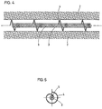
- FIG. 4 represents one possible embodiment among many variants of a stent according to the present invention.
- This stent is in place in an artery or a vessel whose schematically shows the walls 2. It has a part Central 3 which performs the function of flow deflector.
- This deflector 3 is made to using a rolled spring turn spire, in which each turn is connected to the turn adjacent for example using a laser weld.
- the weld points 6 are distributed over a running spiral along the entire length of the spring. In this way, the deflector can not be deformed along the longitudinal axis but nevertheless keeps a some flexibility which facilitates its routing to the area to be treated.
- Both end of the deflector 3, as well as at one or more locations distributed on its length, small turns 4 are welded to the central deflector 3. These turns 4 are expandable radially from a first diameter corresponding approximately to the diameter of the deflector 3 to a second larger diameter corresponding to the diameter of the artery.
- the turns 4 come to bear, in the service position, on the internal walls 2 of the artery and have the same mechanical action on the wall as the stent conventional selfextensives.
- These turns 4, once in contact with the arterial wall keep the deflector 3 in position in the center of the artery and avoid that the latter does not come into contact with the annular wall of the artery.
- FIG 5 we see a passage 5 in the center of the deflector 3.
- This longitudinal passage 5, which extends over all the length of the deflector 3, makes it possible to mount the stent at the end of a catheter angioplasty on a wire guide to facilitate its placement in the treated vessel.
- a material which can be used preferably prestressed at a certain temperature and which returns to its original shape at a higher temperature.
- Nickel and titanium alloys such as Nitinol (registered trademark) are perfectly adapted for the realization of turns 4.
- the turns 4 are cooled and become very malleable. They are then wrapped around the deflector 3. The stent is then conditioned in a catheter.
- the deflector central 3 may also be in the form of a solid cylindrical body provided with a central longitudinal bore, or consist of a hollow cylindrical body which can if necessary serve as a reservoir for a substance to be administered in situ.
- other embodiments of the deflector 3 are possible, in particular the use of several elements assembled as a double spring for example.
- biologically compatible materials such as Nitinol (trademark) or steel stainless.
- some copper alloys may also be considered with a suitable surface treatment, for example a polyester coating or in TEFLON (registered trademark).
- an action was considered therapeutic local or by a surface treatment allowing local distribution of an anti-restenosis substance, either by radiotherapy.
- These techniques can easily be applied to the stent object of the present invention. It is sufficient to provide a suitable surface treatment of the turns 4 in contact with the arterial wall. The cumulative effect of an increase in shear stresses at the level of wall is thus combined with a therapeutic or chemical radio action. It will be noted that not only the parts directly in contact with the arterial wall can present a suitable surface treatment, but also the deflector 3.
- the stent according to the present invention may take other forms, the essential characteristic residing in the presence of a flow deflector increasing the shear stress on the inner wall of the artery and maintained in position in the artery, preferably in the center of the latter.
- the stent may be in the form of a tubular body open at both ends and having in its center a cylindrical body flexibly connected to the body external tubular.
- some stents are made of bio-degradable materials. These materials can of course be used to make a stent according to this invention.
- the method which makes it possible to locally increase the shear stress at the wall of a vessel or artery comprises the following steps.
- the stent is then placed, releasing the stent catheter; during this operation the turns 4 of the stent deviate radially and take support against the inner wall of the artery.
- the stent which is the subject of the present invention is easy to manufacture and can be conditioned in a catheter, so that it is directly usable by the practitioner.
Landscapes
- Health & Medical Sciences (AREA)
- Engineering & Computer Science (AREA)
- Biomedical Technology (AREA)
- Life Sciences & Earth Sciences (AREA)
- General Health & Medical Sciences (AREA)
- Transplantation (AREA)
- Heart & Thoracic Surgery (AREA)
- Vascular Medicine (AREA)
- Cardiology (AREA)
- Animal Behavior & Ethology (AREA)
- Oral & Maxillofacial Surgery (AREA)
- Public Health (AREA)
- Veterinary Medicine (AREA)
- Media Introduction/Drainage Providing Device (AREA)
- Prostheses (AREA)
- Materials For Medical Uses (AREA)
- Surgical Instruments (AREA)
- Dowels (AREA)
Claims (11)
- Stent, dazu bestimmt, in eine Arterie oder ein Blutgefäss eingeführt zu werden, dadurch gekennzeichnet, dass er zumindest eine Strömungsablenkvorrichtung (3) umfasst, die es gestattet, die Strömungslinien radial in Richtung auf die Arterienwandungen abzulenken und so in der Nähe der Arterienwandungen (2) einen grösseren radialen Geschwindigkeitsgradienten zu induzieren, was lokal die Scherbeanspruchung der Arterieninnenwandung (2) erhöht; und dadurch, dass diese Strömungsablenkvorrichtung (3) mit Haltemitteln (4) versehen ist, die in der Arbeitsstellung auf der Innenseite des Gefässes (2) ruhen, wobei diese Mittel (4) die Ablenkvorrichtung (3) daran hindern, mit der Gefässinnenwand (2) in Berührung zu kommen, und eine mechanische Haltewirkung auf die Arterienwandung ausüben.
- Stent nach Anspruch 1, dadurch gekennzeichnet, dass das Verhältnis zwischen dem Radius der Ablenkvorrichtung und dem Radius der Arterie zwischen 0,1 und 0,8 und bevorzugt bei 0,3 liegt.
- Stent nach einem der vorangehenden Ansprüche, dadurch gekennzeichnet, dass die Strömungsablenkvorrichtung(en) (3) eine allgemein zylindrische Gestalt aufweisen.
- Stent nach einem der vorangehenden Ansprüche, dadurch gekennzeichnet, dass die Ablenkvorrichtung (3) aus einer Windung an Windung gewickelten Feder besteht, wo jede Windung mit der folgenden durch einen Schweisspunkt (6) verbunden ist, und dadurch, dass die Haltemittel aus zumindest zwei nachgiebigen, radial ausstreckbaren Windungen (4) bestehen, die mit einem ihrer Enden mit der Ablenkvorrichtung (3) verbunden sind.
- Stent nach Anspruch 4, dadurch gekennzeichnet, dass die Schweisspunkte (6) einer Spirale entlang angeordnet sind, die sich über die ganze Länge der Ablenkvorrichtung (3) erstreckt.
- Stent nach einem der vorangehenden Ansprüche, dadurch gekennzeichnet, dass er eine Mehrzahl von radial ausstreckbaren Windungen (4) umfasst, die mit der Ablenkvorrichtung (3) verbunden und in regelmässigen Abständen über die Längsachse der Ablenkvorrichtung (3) verteilt sind.
- Stent nach einem der vorangehenden Ansprüche, dadurch gekennzeichnet, dass er aus einem Gedächtnismaterial gefertigt ist.
- Stent nach einem der vorangehenden Ansprüche, dadurch gekennzeichnet, dass er ein Radioisotop enthält, das wirksam ist, um die intimale Hyperplasie der Arterienwandung zu verringern.
- Stent nach einem der Ansprüche 1 bis 6, dadurch gekennzeichnet, dass die radial ausstreckbaren Haltemittel (4) und/oder die Ablenkvorrichtung (3) eine spezielle Oberflächenbehandlung aufweisen oder aus einem Biomaterial bestehen, wodurch die Diffusion einer Substanz ermöglicht wird, die eine Wirkung auf die Arterienwandung besitzt.
- Stent nach einem der vorangehenden Ansprüche, dadurch gekennzeichnet, dass die Ablenkvorrichtung (3) einen zentralen Durchlass (5) umfasst, der sich über ihre gesamte Länge erstreckt.
- Stent nach einem der vorangehenden Ansprüche, dadurch gekennzeichnet, dass er aus einem biologisch abbaubaren Material gefertigt ist.
Applications Claiming Priority (3)
| Application Number | Priority Date | Filing Date | Title |
|---|---|---|---|
| CH151497 | 1997-06-20 | ||
| CH01514/97A CH691846A5 (fr) | 1997-06-20 | 1997-06-20 | Implant de dilatation intravasculaire à déflecteur. |
| PCT/IB1998/000948 WO1998058599A1 (fr) | 1997-06-20 | 1998-06-19 | Implant de dilatation intravasculaire a deflecteur |
Publications (2)
| Publication Number | Publication Date |
|---|---|
| EP0989830A1 EP0989830A1 (de) | 2000-04-05 |
| EP0989830B1 true EP0989830B1 (de) | 2004-07-21 |
Family
ID=4212223
Family Applications (1)
| Application Number | Title | Priority Date | Filing Date |
|---|---|---|---|
| EP98924506A Expired - Lifetime EP0989830B1 (de) | 1997-06-20 | 1998-06-19 | Intravaskulärer stent mit einer ablenkvorrichtung |
Country Status (15)
| Country | Link |
|---|---|
| US (2) | US6641605B1 (de) |
| EP (1) | EP0989830B1 (de) |
| JP (1) | JP2002506367A (de) |
| CN (1) | CN1261261A (de) |
| AT (1) | ATE271358T1 (de) |
| AU (1) | AU730691B2 (de) |
| BR (1) | BR9810208A (de) |
| CA (1) | CA2297777A1 (de) |
| CH (1) | CH691846A5 (de) |
| DE (1) | DE69825162T2 (de) |
| ES (1) | ES2222594T3 (de) |
| ID (1) | ID25838A (de) |
| IL (1) | IL133463A0 (de) |
| RU (1) | RU2211006C2 (de) |
| WO (1) | WO1998058599A1 (de) |
Families Citing this family (56)
| Publication number | Priority date | Publication date | Assignee | Title |
|---|---|---|---|---|
| FR2779340B1 (fr) * | 1998-06-04 | 2000-12-29 | Delab | Dispositif intraluminal implantable |
| IL128938A0 (en) | 1999-03-11 | 2000-02-17 | Mind Guard Ltd | Implantable stroke treating device |
| US6673089B1 (en) | 1999-03-11 | 2004-01-06 | Mindguard Ltd. | Implantable stroke treating device |
| ATE270862T1 (de) | 2000-05-09 | 2004-07-15 | Endoart Sa | Mit einem zentralen deflektor versehenes vaskuläres implantat |
| EP1153580A1 (de) | 2000-05-09 | 2001-11-14 | EndoArt S.A. | Herstellungsverfahren für einen intravaskulären Deflektor und daraus hergestelltes Implantat |
| AU2002229026A1 (en) * | 2000-11-13 | 2002-05-21 | Young Cho | Device and method for reducing blood pressure |
| EP1234554A1 (de) * | 2001-02-21 | 2002-08-28 | EndoArt SA | Gefässimplantat mit einer inneren Ablenkvorrichtung |
| US20030100945A1 (en) | 2001-11-23 | 2003-05-29 | Mindguard Ltd. | Implantable intraluminal device and method of using same in treating aneurysms |
| GB2373058B (en) * | 2001-09-18 | 2003-02-19 | Tayside Flow Technologies Ltd | Spiral flow testing |
| GB2384189A (en) * | 2001-11-21 | 2003-07-23 | Tayside Flow Technologies Ltd | Helix shaped insert for flow moification in a duct or stent |
| EP1374799A1 (de) * | 2002-06-18 | 2004-01-02 | F.R.I.D. R&D Benelux Sprl | Hemodynamisch, luminale Endoprothese |
| FR2845884B1 (fr) * | 2002-10-22 | 2005-07-22 | Centre Nat Rech Scient | Outil terminal d'instrument chirurgical. |
| US6972025B2 (en) * | 2003-11-18 | 2005-12-06 | Scimed Life Systems, Inc. | Intravascular filter with bioabsorbable centering element |
| WO2006042114A1 (en) | 2004-10-06 | 2006-04-20 | Cook, Inc. | Emboli capturing device having a coil and method for capturing emboli |
| US8221446B2 (en) | 2005-03-15 | 2012-07-17 | Cook Medical Technologies | Embolic protection device |
| US8945169B2 (en) | 2005-03-15 | 2015-02-03 | Cook Medical Technologies Llc | Embolic protection device |
| US7850708B2 (en) | 2005-06-20 | 2010-12-14 | Cook Incorporated | Embolic protection device having a reticulated body with staggered struts |
| US8109962B2 (en) | 2005-06-20 | 2012-02-07 | Cook Medical Technologies Llc | Retrievable device having a reticulation portion with staggered struts |
| US7766934B2 (en) | 2005-07-12 | 2010-08-03 | Cook Incorporated | Embolic protection device with an integral basket and bag |
| US7771452B2 (en) | 2005-07-12 | 2010-08-10 | Cook Incorporated | Embolic protection device with a filter bag that disengages from a basket |
| US9642726B2 (en) | 2005-07-25 | 2017-05-09 | Vascular Dynamics, Inc. | Devices and methods for control of blood pressure |
| US8923972B2 (en) | 2005-07-25 | 2014-12-30 | Vascular Dynamics, Inc. | Elliptical element for blood pressure reduction |
| US9592136B2 (en) | 2005-07-25 | 2017-03-14 | Vascular Dynamics, Inc. | Devices and methods for control of blood pressure |
| US9125732B2 (en) | 2005-07-25 | 2015-09-08 | Vascular Dynamics, Inc. | Devices and methods for control of blood pressure |
| US8187298B2 (en) | 2005-08-04 | 2012-05-29 | Cook Medical Technologies Llc | Embolic protection device having inflatable frame |
| US8377092B2 (en) | 2005-09-16 | 2013-02-19 | Cook Medical Technologies Llc | Embolic protection device |
| US8632562B2 (en) | 2005-10-03 | 2014-01-21 | Cook Medical Technologies Llc | Embolic protection device |
| US8182508B2 (en) | 2005-10-04 | 2012-05-22 | Cook Medical Technologies Llc | Embolic protection device |
| US8252017B2 (en) | 2005-10-18 | 2012-08-28 | Cook Medical Technologies Llc | Invertible filter for embolic protection |
| US8216269B2 (en) | 2005-11-02 | 2012-07-10 | Cook Medical Technologies Llc | Embolic protection device having reduced profile |
| US8152831B2 (en) | 2005-11-17 | 2012-04-10 | Cook Medical Technologies Llc | Foam embolic protection device |
| US20080071307A1 (en) | 2006-09-19 | 2008-03-20 | Cook Incorporated | Apparatus and methods for in situ embolic protection |
| US9943409B2 (en) | 2006-11-14 | 2018-04-17 | The United States Of America, As Represented By The Secretary, Department Of Health And Human Services | Transcatheter coronary sinus mitral valve annuloplasty procedure and coronary artery and myocardial protection device |
| EP2091465B1 (de) * | 2006-11-14 | 2018-01-31 | The Government of the United States of America as represented by the Secretary of the Department of Health and Human Services | Herzmuskelschutzvorrichtung |
| US9901434B2 (en) | 2007-02-27 | 2018-02-27 | Cook Medical Technologies Llc | Embolic protection device including a Z-stent waist band |
| AU2008246928B2 (en) | 2007-05-07 | 2014-04-17 | Protalix Ltd. | Large scale disposable bioreactor |
| EP1998054B1 (de) * | 2007-05-24 | 2014-08-13 | Parker Origa Holding AG | Pneumatikzylinder mit einer selbsteinstellenden Endlagendämpfung und entsprechendes Verfahren |
| US9138307B2 (en) | 2007-09-14 | 2015-09-22 | Cook Medical Technologies Llc | Expandable device for treatment of a stricture in a body vessel |
| US8419748B2 (en) | 2007-09-14 | 2013-04-16 | Cook Medical Technologies Llc | Helical thrombus removal device |
| US8252018B2 (en) | 2007-09-14 | 2012-08-28 | Cook Medical Technologies Llc | Helical embolic protection device |
| EP2346405B1 (de) | 2008-09-26 | 2019-03-13 | Vascular Dynamics Inc. | Vorrichtungen und verfahren zur kontrolle des blutdrucks |
| US8388644B2 (en) | 2008-12-29 | 2013-03-05 | Cook Medical Technologies Llc | Embolic protection device and method of use |
| GB2514135B (en) | 2013-05-14 | 2015-04-15 | Cook Medical Technologies Llc | Implantable flow diverter |
| JP5814976B2 (ja) * | 2013-05-15 | 2015-11-17 | 三菱電機株式会社 | 電流計測装置 |
| GB2519932B (en) | 2013-08-13 | 2015-10-21 | Cook Medical Technologies Llc | Implantable flow adjuster |
| US20150157475A1 (en) | 2013-12-06 | 2015-06-11 | Abbott Cardiovascular Systems Inc. | Deflector for increased wall shear stress adjacent an arteriovenous fistula |
| US9687239B2 (en) | 2014-04-15 | 2017-06-27 | Abbott Cardiovascular Systems Inc. | Intravascular devices supporting an arteriovenous fistula |
| RU2597408C1 (ru) * | 2015-05-08 | 2016-09-10 | Валерий Вильгельмович Петрашкевич | Внутрисосудистый расширительный имплантат |
| US11039923B2 (en) | 2016-05-06 | 2021-06-22 | Transmural Systems Llc | Annuloplasty procedures, related devices and methods |
| US12544227B2 (en) | 2016-05-06 | 2026-02-10 | Transmural Systems Llc | Annuloplasty procedures, related devices and methods |
| KR102416646B1 (ko) | 2016-05-06 | 2022-07-06 | 더 유나이티드 스테이츠 오브 어메리카, 애즈 리프리젠티드 바이 더 세크러테리, 디파트먼트 오브 헬쓰 앤드 휴먼 서비씨즈 | 고리성형술 절차들, 관련된 기기들 및 방법들 |
| US11007059B2 (en) | 2016-05-06 | 2021-05-18 | Transmural Systems Llc | Annuloplasty procedures, related devices and methods |
| US11980545B2 (en) | 2016-05-06 | 2024-05-14 | Transmural Systems Llc | Annuloplasty procedures, related devices and methods |
| EP3551140A4 (de) | 2016-12-09 | 2020-07-08 | Zenflow, Inc. | Systeme, vorrichtungen und verfahren zur präzisen freisetzung eines implantats in der prostatischen harnröhre |
| KR102670640B1 (ko) | 2017-08-26 | 2024-05-30 | 트랜스뮤럴 시스템스 엘엘씨 | 심장 고리성형술 및 조율 시술, 그리고 관련 장치 및 방법 |
| WO2021101951A1 (en) | 2019-11-19 | 2021-05-27 | Zenflow, Inc. | Systems, devices, and methods for the accurate deployment and imaging of an implant in the prostatic urethra |
Family Cites Families (22)
| Publication number | Priority date | Publication date | Assignee | Title |
|---|---|---|---|---|
| US3334629A (en) * | 1964-11-09 | 1967-08-08 | Bertram D Cohn | Occlusive device for inferior vena cava |
| US3868956A (en) * | 1972-06-05 | 1975-03-04 | Ralph J Alfidi | Vessel implantable appliance and method of implanting it |
| EP0556940A1 (de) * | 1986-02-24 | 1993-08-25 | Robert E. Fischell | Intravaskulärer Stent |
| WO1990001969A1 (en) * | 1988-08-24 | 1990-03-08 | Slepian Marvin J | Biodegradable polymeric endoluminal sealing |
| US5292331A (en) * | 1989-08-24 | 1994-03-08 | Applied Vascular Engineering, Inc. | Endovascular support device |
| US5059166A (en) * | 1989-12-11 | 1991-10-22 | Medical Innovative Technologies R & D Limited Partnership | Intra-arterial stent with the capability to inhibit intimal hyperplasia |
| US5282847A (en) * | 1991-02-28 | 1994-02-01 | Medtronic, Inc. | Prosthetic vascular grafts with a pleated structure |
| FR2679127B1 (fr) * | 1991-07-16 | 1993-11-26 | Van Cleef Jean Francois | Dispositif intraveineux d'obstruction ou de maintien. |
| US5129910A (en) | 1991-07-26 | 1992-07-14 | The Regents Of The University Of California | Stone expulsion stent |
| US5304194A (en) | 1991-10-02 | 1994-04-19 | Target Therapeutics | Vasoocclusion coil with attached fibrous element(s) |
| US5290305A (en) * | 1991-10-11 | 1994-03-01 | Kanji Inoue | Appliance collapsible for insertion into human organs and capable of resilient restoration |
| US5626605A (en) * | 1991-12-30 | 1997-05-06 | Scimed Life Systems, Inc. | Thrombosis filter |
| RU2120253C1 (ru) * | 1992-08-06 | 1998-10-20 | Вилльям Кук Юроп А/С | Протезное устройство для поддержания просвета сосуда или полого органа |
| US5378234A (en) * | 1993-03-15 | 1995-01-03 | Pilot Cardiovascular Systems, Inc. | Coil polymer composite |
| US5573547A (en) * | 1993-10-19 | 1996-11-12 | Leveen; Harry H. | Brush fixation method for attachment of tissues and occlusion of blood vessels |
| IT1274098B (it) * | 1994-11-08 | 1997-07-15 | Xtrode Srl | Endoprotesi coronarica |
| IT1278164B1 (it) * | 1995-01-20 | 1997-11-17 | Trode Srl X | Endoprotesi coronarica e metodo per la sua realizzazione |
| US6143007A (en) * | 1995-04-28 | 2000-11-07 | Target Therapeutics, Inc. | Method for making an occlusive device |
| US5871436A (en) * | 1996-07-19 | 1999-02-16 | Advanced Cardiovascular Systems, Inc. | Radiation therapy method and device |
| ZA9710342B (en) * | 1996-11-25 | 1998-06-10 | Alza Corp | Directional drug delivery stent and method of use. |
| US5855597A (en) * | 1997-05-07 | 1999-01-05 | Iowa-India Investments Co. Limited | Stent valve and stent graft for percutaneous surgery |
| RU7599U1 (ru) * | 1997-12-18 | 1998-09-16 | Виктор Томович Партош | Внутрисосудистый эндопротез |
-
1997
- 1997-06-20 CH CH01514/97A patent/CH691846A5/fr not_active IP Right Cessation
-
1998
- 1998-06-19 ID IDW991645A patent/ID25838A/id unknown
- 1998-06-19 DE DE69825162T patent/DE69825162T2/de not_active Expired - Fee Related
- 1998-06-19 US US09/446,355 patent/US6641605B1/en not_active Expired - Fee Related
- 1998-06-19 ES ES98924506T patent/ES2222594T3/es not_active Expired - Lifetime
- 1998-06-19 WO PCT/IB1998/000948 patent/WO1998058599A1/fr not_active Ceased
- 1998-06-19 BR BR9810208-7A patent/BR9810208A/pt not_active Application Discontinuation
- 1998-06-19 IL IL13346398A patent/IL133463A0/xx unknown
- 1998-06-19 CN CN98806396A patent/CN1261261A/zh active Pending
- 1998-06-19 AT AT98924506T patent/ATE271358T1/de not_active IP Right Cessation
- 1998-06-19 EP EP98924506A patent/EP0989830B1/de not_active Expired - Lifetime
- 1998-06-19 CA CA002297777A patent/CA2297777A1/en not_active Abandoned
- 1998-06-19 JP JP50404199A patent/JP2002506367A/ja active Pending
- 1998-06-19 RU RU2000101327/14A patent/RU2211006C2/ru not_active IP Right Cessation
- 1998-06-19 AU AU76694/98A patent/AU730691B2/en not_active Ceased
-
2002
- 2002-06-07 US US10/163,465 patent/US7094254B2/en not_active Expired - Fee Related
Also Published As
| Publication number | Publication date |
|---|---|
| JP2002506367A (ja) | 2002-02-26 |
| CH691846A5 (fr) | 2001-11-15 |
| RU2211006C2 (ru) | 2003-08-27 |
| DE69825162D1 (de) | 2004-08-26 |
| WO1998058599A1 (fr) | 1998-12-30 |
| EP0989830A1 (de) | 2000-04-05 |
| IL133463A0 (en) | 2001-04-30 |
| US20020198591A1 (en) | 2002-12-26 |
| US6641605B1 (en) | 2003-11-04 |
| BR9810208A (pt) | 2000-08-08 |
| US7094254B2 (en) | 2006-08-22 |
| CN1261261A (zh) | 2000-07-26 |
| ES2222594T3 (es) | 2005-02-01 |
| ATE271358T1 (de) | 2004-08-15 |
| AU7669498A (en) | 1999-01-04 |
| CA2297777A1 (en) | 1998-12-30 |
| AU730691B2 (en) | 2001-03-15 |
| DE69825162T2 (de) | 2005-07-28 |
| ID25838A (id) | 2000-11-09 |
Similar Documents
| Publication | Publication Date | Title |
|---|---|---|
| EP0989830B1 (de) | Intravaskulärer stent mit einer ablenkvorrichtung | |
| EP0843538B1 (de) | Interne ausdehnbare manschette zum chirurgischen gebrauch zur dehnung physiologischer gefässe | |
| EP0897309B1 (de) | Katheter zur lokalen verabreichung einer therapeutisch aktiven substanz | |
| EP0892626B1 (de) | Implantierbare vorrichtung zum festerhalten oder wiederherstellen eines normalen körpergefässquerschnittes | |
| BE1009278A3 (fr) | Tuteur auto-expansible pour dispositif medical a introduire dans une cavite d'un corps, et dispositif medical muni d'un tel tuteur. | |
| EP0603959B1 (de) | Endoluminale Prothese und ihre Herstellungsmethode | |
| WO1997024080A1 (fr) | Ensemble de traitement chirurgical d'une lumiere intracorporelle | |
| BE1024922B1 (fr) | Système de mise en place d'un stent bifurqué | |
| WO1999055253A1 (fr) | Endoprothese vasculaire tubulaire et flexible | |
| EP1082068B1 (de) | Implantierbare intraluminale vorrichtung | |
| US20060020329A1 (en) | Semi-directional drug delivering stents | |
| US7063720B2 (en) | Covered stent with controlled therapeutic agent diffusion | |
| FR2843297A1 (fr) | Ensemble medical et procede pour la sortie controlee d'une prothese expansible dans un conduit corporel | |
| WO2009147349A1 (fr) | Dispositif medical implantable avec un moyen de positionnement a un endroit precis d'embranchement d ' un vaisseau sanguin tel qu'une coronaire | |
| FR2671482A1 (fr) | Endoprothese vasculaire. | |
| FR2768921A1 (fr) | Ensemble comprenant une prothese intraluminale et un moyen d'etancheite de cette prothese | |
| US9149375B2 (en) | Radiopaque drug-filled prosthesis and method of making same | |
| WO2013160829A1 (fr) | Prothese vasculaire endoluminale pour petits vaisseaux | |
| FR2846872A1 (fr) | Dispositif formant endoprothese presentant des extremites reduites | |
| EP1684664A1 (de) | Endoprothese mit verjüngten enden | |
| FR2974726A1 (fr) | Dispositif de dilatation pour organe tubulaire |
Legal Events
| Date | Code | Title | Description |
|---|---|---|---|
| PUAI | Public reference made under article 153(3) epc to a published international application that has entered the european phase |
Free format text: ORIGINAL CODE: 0009012 |
|
| 17P | Request for examination filed |
Effective date: 19991220 |
|
| AK | Designated contracting states |
Kind code of ref document: A1 Designated state(s): AT BE CH CY DE DK ES FI FR GB GR IE IT LI LU MC NL PT SE |
|
| AX | Request for extension of the european patent |
Free format text: AL PAYMENT 19991220;LT PAYMENT 19991220;LV PAYMENT 19991220;MK PAYMENT 19991220;RO PAYMENT 19991220;SI PAYMENT 19991220 |
|
| GRAP | Despatch of communication of intention to grant a patent |
Free format text: ORIGINAL CODE: EPIDOSNIGR1 |
|
| RAP1 | Party data changed (applicant data changed or rights of an application transferred) |
Owner name: ECOLE POLYTECHNIQUE FEDERALE DE LAUSANNE |
|
| GRAS | Grant fee paid |
Free format text: ORIGINAL CODE: EPIDOSNIGR3 |
|
| GRAA | (expected) grant |
Free format text: ORIGINAL CODE: 0009210 |
|
| AK | Designated contracting states |
Kind code of ref document: B1 Designated state(s): AT BE CH CY DE DK ES FI FR GB GR IE IT LI LU MC NL PT SE |
|
| AX | Request for extension of the european patent |
Extension state: AL LT LV MK RO SI |
|
| PG25 | Lapsed in a contracting state [announced via postgrant information from national office to epo] |
Ref country code: NL Free format text: LAPSE BECAUSE OF FAILURE TO SUBMIT A TRANSLATION OF THE DESCRIPTION OR TO PAY THE FEE WITHIN THE PRESCRIBED TIME-LIMIT Effective date: 20040721 Ref country code: IE Free format text: LAPSE BECAUSE OF FAILURE TO SUBMIT A TRANSLATION OF THE DESCRIPTION OR TO PAY THE FEE WITHIN THE PRESCRIBED TIME-LIMIT Effective date: 20040721 Ref country code: FI Free format text: LAPSE BECAUSE OF FAILURE TO SUBMIT A TRANSLATION OF THE DESCRIPTION OR TO PAY THE FEE WITHIN THE PRESCRIBED TIME-LIMIT Effective date: 20040721 Ref country code: AT Free format text: LAPSE BECAUSE OF FAILURE TO SUBMIT A TRANSLATION OF THE DESCRIPTION OR TO PAY THE FEE WITHIN THE PRESCRIBED TIME-LIMIT Effective date: 20040721 |
|
| REG | Reference to a national code |
Ref country code: GB Ref legal event code: FG4D Free format text: NOT ENGLISH |
|
| REG | Reference to a national code |
Ref country code: CH Ref legal event code: EP |
|
| REG | Reference to a national code |
Ref country code: IE Ref legal event code: FG4D Free format text: FRENCH |
|
| REF | Corresponds to: |
Ref document number: 69825162 Country of ref document: DE Date of ref document: 20040826 Kind code of ref document: P |
|
| GBT | Gb: translation of ep patent filed (gb section 77(6)(a)/1977) |
Effective date: 20040812 |
|
| PG25 | Lapsed in a contracting state [announced via postgrant information from national office to epo] |
Ref country code: SE Free format text: LAPSE BECAUSE OF FAILURE TO SUBMIT A TRANSLATION OF THE DESCRIPTION OR TO PAY THE FEE WITHIN THE PRESCRIBED TIME-LIMIT Effective date: 20041021 Ref country code: GR Free format text: LAPSE BECAUSE OF FAILURE TO SUBMIT A TRANSLATION OF THE DESCRIPTION OR TO PAY THE FEE WITHIN THE PRESCRIBED TIME-LIMIT Effective date: 20041021 Ref country code: DK Free format text: LAPSE BECAUSE OF FAILURE TO SUBMIT A TRANSLATION OF THE DESCRIPTION OR TO PAY THE FEE WITHIN THE PRESCRIBED TIME-LIMIT Effective date: 20041021 |
|
| LTIE | Lt: invalidation of european patent or patent extension |
Effective date: 20040721 |
|
| NLV1 | Nl: lapsed or annulled due to failure to fulfill the requirements of art. 29p and 29m of the patents act | ||
| REG | Reference to a national code |
Ref country code: ES Ref legal event code: FG2A Ref document number: 2222594 Country of ref document: ES Kind code of ref document: T3 |
|
| REG | Reference to a national code |
Ref country code: IE Ref legal event code: FD4D |
|
| PLBE | No opposition filed within time limit |
Free format text: ORIGINAL CODE: 0009261 |
|
| STAA | Information on the status of an ep patent application or granted ep patent |
Free format text: STATUS: NO OPPOSITION FILED WITHIN TIME LIMIT |
|
| PG25 | Lapsed in a contracting state [announced via postgrant information from national office to epo] |
Ref country code: LU Free format text: LAPSE BECAUSE OF NON-PAYMENT OF DUE FEES Effective date: 20050619 Ref country code: CY Free format text: LAPSE BECAUSE OF FAILURE TO SUBMIT A TRANSLATION OF THE DESCRIPTION OR TO PAY THE FEE WITHIN THE PRESCRIBED TIME-LIMIT Effective date: 20050619 |
|
| PG25 | Lapsed in a contracting state [announced via postgrant information from national office to epo] |
Ref country code: MC Free format text: LAPSE BECAUSE OF NON-PAYMENT OF DUE FEES Effective date: 20050630 Ref country code: LI Free format text: LAPSE BECAUSE OF NON-PAYMENT OF DUE FEES Effective date: 20050630 Ref country code: CH Free format text: LAPSE BECAUSE OF NON-PAYMENT OF DUE FEES Effective date: 20050630 Ref country code: BE Free format text: LAPSE BECAUSE OF NON-PAYMENT OF DUE FEES Effective date: 20050630 |
|
| 26N | No opposition filed |
Effective date: 20050422 |
|
| REG | Reference to a national code |
Ref country code: CH Ref legal event code: PL |
|
| REG | Reference to a national code |
Ref country code: HK Ref legal event code: WD Ref document number: 1026603 Country of ref document: HK |
|
| BERE | Be: lapsed |
Owner name: *ECOLE POLYTECHNIQUE FEDERALE DE LAUSANNE Effective date: 20050630 |
|
| PG25 | Lapsed in a contracting state [announced via postgrant information from national office to epo] |
Ref country code: PT Free format text: LAPSE BECAUSE OF NON-PAYMENT OF DUE FEES Effective date: 20041221 |
|
| PGFP | Annual fee paid to national office [announced via postgrant information from national office to epo] |
Ref country code: ES Payment date: 20080627 Year of fee payment: 11 |
|
| PGFP | Annual fee paid to national office [announced via postgrant information from national office to epo] |
Ref country code: IT Payment date: 20080624 Year of fee payment: 11 |
|
| PGFP | Annual fee paid to national office [announced via postgrant information from national office to epo] |
Ref country code: DE Payment date: 20080620 Year of fee payment: 11 |
|
| PGFP | Annual fee paid to national office [announced via postgrant information from national office to epo] |
Ref country code: FR Payment date: 20080613 Year of fee payment: 11 |
|
| PGFP | Annual fee paid to national office [announced via postgrant information from national office to epo] |
Ref country code: GB Payment date: 20080620 Year of fee payment: 11 |
|
| GBPC | Gb: european patent ceased through non-payment of renewal fee |
Effective date: 20090619 |
|
| REG | Reference to a national code |
Ref country code: FR Ref legal event code: ST Effective date: 20100226 |
|
| PG25 | Lapsed in a contracting state [announced via postgrant information from national office to epo] |
Ref country code: FR Free format text: LAPSE BECAUSE OF NON-PAYMENT OF DUE FEES Effective date: 20090630 |
|
| PG25 | Lapsed in a contracting state [announced via postgrant information from national office to epo] |
Ref country code: GB Free format text: LAPSE BECAUSE OF NON-PAYMENT OF DUE FEES Effective date: 20090619 |
|
| PG25 | Lapsed in a contracting state [announced via postgrant information from national office to epo] |
Ref country code: DE Free format text: LAPSE BECAUSE OF NON-PAYMENT OF DUE FEES Effective date: 20100101 |
|
| REG | Reference to a national code |
Ref country code: ES Ref legal event code: FD2A Effective date: 20090620 |
|
| PG25 | Lapsed in a contracting state [announced via postgrant information from national office to epo] |
Ref country code: ES Free format text: LAPSE BECAUSE OF NON-PAYMENT OF DUE FEES Effective date: 20090620 |
|
| PG25 | Lapsed in a contracting state [announced via postgrant information from national office to epo] |
Ref country code: IT Free format text: LAPSE BECAUSE OF NON-PAYMENT OF DUE FEES Effective date: 20090619 |